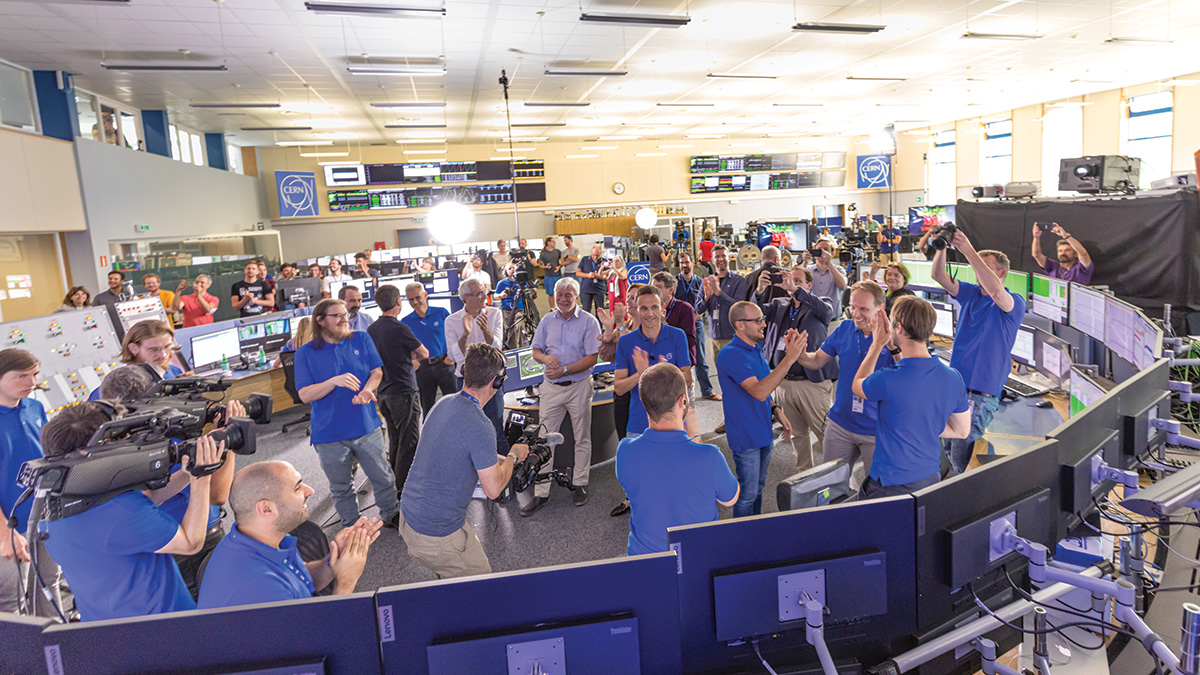
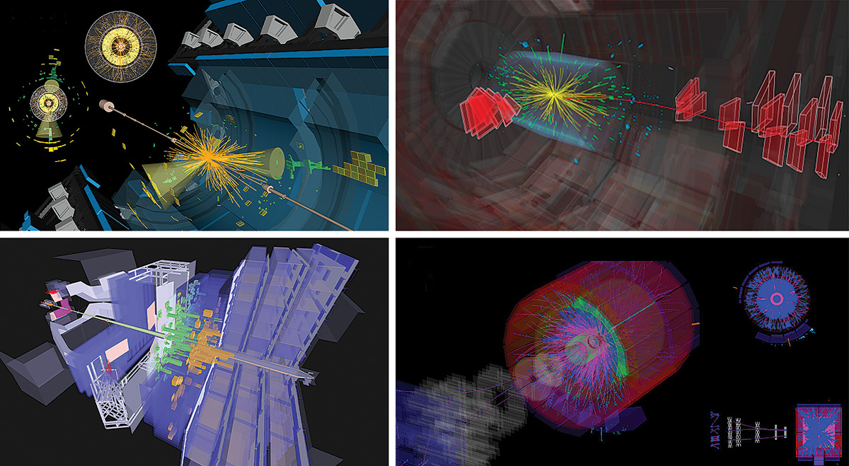
At 4.47 p.m. on Tuesday 5 July, applause broke out in the CERN Control Centre as LHC operators declared Stable Beams. After more than three years of upgrade and maintenance work across the machine and experiments, ALICE, ATLAS, CMS and LHCb started recording their first proton–proton collisions at an unprecedented energy of 13.6 TeV.
LHC Run 3 is set to last until December 2025. In addition to a slightly higher centre-of-mass energy than Run 2, the machine will operate at an increased average luminosity thanks to larger proton intensities and smaller transverse beam sizes. New or upgraded detectors and improved data readout and selection promise the experiments their greatest physics harvests yet. ATLAS and CMS each expect to record more collisions during Run 3 than in the two previous runs combined, while LHCb and ALICE hope for three and 50 times more data, respectively. Two new forward experiments, FASER and SND@LHC (CERN Courier July/August 2021 p7), also join the LHC-experiment family.
While pilot beams circulated in the LHC for a brief period in October 2021, the countdown to LHC Run 3 began in earnest on 22 April, when two beams of protons circulated in opposite directions at their injection energy of 450 GeV. Since then, operators have worked around the clock to ensure the smooth beginning of the LHC’s third run, which was livestreamed to the media on the afternoon of 5 July. True to form, the machine added drama to proceedings: a training quench that morning generated enough heat to warm up several magnets well above their operating temperature. The cryogenics team sprang into action, managing to recuperate operational conditions just in time for the live event, watched by more than 1.5 million people.
Since then, the intensity of the beams has been increased in carefully monitored steps. As the Courier went to press, 900 bunches each containing around 120 billion protons were circulating, with 2748 bunches expected by September. “Run 3 is going to be a game-changer for us,” says operations group leader Rende Steerenberg. “In Run 2, we exploited the LHC in its ‘normal’ hardware configuration as constructed. Now, after the injectors have been adapted, we can push the brightness and the intensity of the beams much more. Run 3 is also an important stepping-stone to the High-Luminosity LHC upgrade.”
Schedule change
In March, the CERN management announced a change to the LHC schedule. Long Shutdown 3 will now start in December 2025, one year later than in the previous baseline, and last for three instead of 2.5 years. Production schedules across the LHC’s lifetime will remain unaffected, while the change will allow work for the HL-LHC to be completed with appropriate schedule margins. The extended year-end technical stop (EYETS) is now scheduled to take place in 2024/2025 and to last for 17 weeks, while the two preceding EYETSs will be of the standard length of 13 weeks beam-to-beam.
The preferred scenarios and duration of ion runs during Run 3 remain to be confirmed, but are likely to take place in four week-long periods towards the end of each year. While the majority of the LHC’s heavy-ion runs employ lead ions, a novel addition to the Run 3 programme will be a short period of collisions between oxygen ions in 2024. As with the first xenon runs in 2017, colliding ions with masses that are intermediate between protons and lead allows the experiments to scan important physics regimes relevant to the study of high-energy QCD.
“Every time you make a step in energy, even if it’s not that large, and a step in the amount of data, you open up new physics opportunities,” said CERN Director-General Fabiola Gianotti. “And every time we start a new run, it’s always a new adventure. You have to recalibrate the detectors and the accelerator, so it’s always uncharted territory and always a big emotion.”
For full coverage of the physics targets at LHC Run 3, please see the May/June 2022 issue of CERN Courier.
The first Italian workshop on the Future Circular Collider (FCC) took place in Rome from 21 to 22 March and was attended by around 120 researchers.
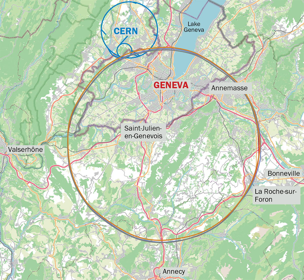
The FCC study is exploring the technical and financial feasibility of a 91 km-circumference collider situated under French and Swiss territory near CERN, thus exploiting existing infrastructures. In a first phase (FCC-ee) the tunnel would host an electron–positron collider at energies from 90 to 365 GeV, which would be replaced by a proton–proton collider (FCC-hh) with a centre-of-mass energy of at least 100 TeV, almost an order of magnitude higher than that of the LHC. The proposed roadmap foresees the R&D for the 16 T superconducting dipole magnets needed to keep the FCC-hh proton beams on track to take place in parallel with FCC-ee construction and operation.
“The FCC is a large infrastructure that would allow Europe to maintain its worldwide leadership in high-energy physics research. This project is therefore of strategic importance in the international science scenario of the coming years,” remarked INFN president Antonio Zoccoli in his introduction. “INFN has great potential and could make a significant contribution to its implementation. In this perspective, it is important to clearly identify the main activities in which to invest, assemble the necessary human resources and identify possible industrial partners.”
The workshop was opened by FCC study leader Michael Benedikt, who gave an overview of the FCC feasibility study, while deputy study leader Frank Zimmermann covered the technological challenges, design features and machine studies for FCC-ee. Opportunities for technological development related to the FCC-ee were then presented, along with machine studies, in which INFN are already involved. Scientific and technological R&D areas where collaborations could be strengthened or initiated were also identified, prompting an interesting discussion with CERN colleagues.
INFN is already well integrated both in the FCC coordination structure and several ongoing studies, having participated in the project since its beginning, and provides important contributions on all aspects of the FCC study. These range from accelerator and detector R&D, such as the development of superconducting magnets, to experimental and theoretical physics studies. This is made evident by the strong Italian involvement in FCC-related European programmes, such as EuroCirCol for FCC-hh and FCC-IS for FCC-ee, and AIDAinnova on innovative detector technologies for future accelerators. INFN is committed to the development of superconducting magnets for FCC-hh, for which substantial additional funding could come from a project in the context of the next-generation funding programme Horizon Europe.
The second day of the workshop focused on the work that experimental and theoretical physicists have been carrying out to deeply understand the scientific potential of the visionary FCC project, the specific requests for the detectors and the associated R&D activities.
This workshop was the first in a series organised by INFN to promote and support the FCC project and pursue the key technological R&D needed to demonstrate its feasibility by the next update of the European strategy for particle physics.
Despite several COVID waves, the organisers of the 6th edition of the International Summer School on Intelligent Signal Processing for Frontier Research and Industry (INFIERI) made this school an in-person event. The INFIERI school was successfully held at UAM from August 23 to September 4 thanks to the unprecedented speed of the vaccine roll out, the responsible behaviour of the school participants and the proper applied logistics.
Against a backdrop of topics ranging from cosmology to the human body and particle physics, the programme covered advanced technologies such as semiconductors, deep sub-micron 3D technologies, data transmission, artificial intelligence and quantum computing.
Topics were presented in lectures and keynote speeches, and the teaching was reinforced via hands-on laboratory sessions, allowing students to practise applications in realistic conditions across a range of areas, such as: theoretical physics, accelerators, quantum communication, Si Photonics and nanotechnology. The latter included medical applications to new mRNA vaccines, which have long been under investigation for cancer treatment, besides their use against COVID-19. For instance, they could analyse combined real PET/MRI images using machine-learning techniques to find biomarkers of illness in a hospital setting, or study the irradiation of a biomaterial using a proton beam. Worldwide experts from academia, industry and laboratories such as CERN either gave lectures or ran lab sessions, most of them attending in person, often for the entire duration of the school.
During the last day, the students presented posters on their own research projects – the high number and quality of presentations reflecting the cross-disciplinary facets and the excellence of the participants. Many were then selected to be part of the in-preparation proceedings of the Journal of Instrumentation.
The next INFIERI school will only offer in-person attendance, which is considered essential to the series, but if the pandemic continues it will exploit some of the learning gained from the 6th edition.
19 September 2008: the LHC was without beam because of a transformer problem. The hardware commissioning team were finishing off powering tests of the main dipole magnet circuit in sector 3–4 when, at 11:18, an electrical fault resulted in considerable physical damage, the release of helium, and debris in a long section of the machine. In the control room, the alarms came swamping in. The cryogenics team grappled to make sense of what their systems were telling them, and there was frantic effort to interpret the data from the LHC’s quench protection system. I called LHC project leader Lyn Evans: “looks like we’ve got a serious problem here”.
Up to this point, 2008 had been non-stop but things were looking good. First circulating beam had been established nine days earlier in a blaze of publicity. Beam commissioning had started in earnest, and the rate of progress was catching some of us by surprise.
It is hard to describe how much of a body blow the sector 3–4 incident was to the community. In the following days, as the extent of the damage became clearer, I remember talking to Glyn Kirby of the magnet team and being aghast when he observed that “it’s going to take at least a year to fix”. He was, of course, right.
What followed was a truly remarkable effort by everyone involved. A total of 53 cryomagnets (39 dipoles and 14 quadrupoles) covering most of the affected 700 m-long zone were removed and brought to the surface for inspection, cleaning and repair or reuse. Most of the removed magnets were replaced by spares. All magnets whatever their origin had to undergo full functional tests before being installed.
Soot in the vacuum pipes, which had been found to extend beyond the zone of removed magnets, was cleared out using endoscopy and mechanical cleaning. The complete length of the beam pipes was inspected for contamination by flakes of multilayer insulation, which were removed by vacuum cleaning. About 100 plug-in modules installed in the magnet interconnects were replaced.
Following an in-depth analysis of the root causes of the incident, and an understanding of the risks posed by the joints in the magnet interconnects, a new worst-case Maximum Credible Incident was adopted and a wide range of recommendations and mitigation measures were proposed and implemented. These included a major upgrade of the quench protection system, new helium pressure-release ports, and new longitudinal restraints for selected magnets.
One major consequence of the 19 September incident was the decision to run at a lower-than-design energy until full consolidation of the joints had been performed – hence the adoption of an operational beam energy of 3.5 TeV for Run 1. Away from the immediate recovery, other accelerator teams took the opportunity to consolidate and improve controls, hardware systems, instrumentation, software and operational procedures. As CMS technical coordinator Austin Ball famously noted, come the 2009 restart, CMS, at least, was in an “unprecedented state of readiness”.
Take two
Beam was circulated again on 20 November 2009. Progress thereafter was rapid. Collisions with stable-beam conditions were quickly established at 450 + 450 GeV, and a ramp to the maximum beam energy at the time (1.18 TeV, compared to the Tevatron’s 0.98 TeV) was successfully performed on 30 November. The first ramps were a lot of fun – there’s a lot going on behind the scenes, including compensation of significant field dynamics in the superconducting dipoles. Cue much relief when beam made it up the ramp for the first time. All beam-based systems were at least partially commissioned and LHC operations started a long process to master the control of a hugely complex machine. Following continued deployment of the upgraded quench protection system during the 2009 year-end technical stop, commissioning with beam started again in the new year. Progress was good, with first colliding beams at 3.5 + 3.5 TeV being established under the watchful eye of the media on 30 March 2010. With scheduled collisions delayed by two unsuccessful ramps, it was a gut-knotting experience in the control room. Nonetheless, we finally got there about three hours late. “Stable Beams” was declared, the odd beer was had, and we were off.
Essentially 2010 was then devoted to commissioning and establishing confidence in operational procedures and the machine protection system, before starting to increase the number of bunches in the beam. In June the decision was taken to go for bunches with nominal population (~1.2 × 10¹¹ protons), which involved another extended commissioning period. Up to this point, in deference to machine-protection concerns, only around one fifth of the nominal bunch population had been used. To further increase the number of bunches, the move to a bunch separation of 150 ns was made and the crossing angle bumps spanning the experiments’ insertion regions were deployed. After a carefully phased increase in total intensity, the proton run finished with beams of 368 bunches of around 1.2 × 10¹¹ protons per bunch, and a peak luminosity of 2.1 × 1032 cm–2s–1.
Looking back, 2010 was a profoundly important year for a chastened and cautious accelerator sector. The energy stored in the magnets had demonstrated its destructive power, and it was clear from the start that the beam was to be treated with the utmost respect; safe exploitation of the machine was necessarily an underlying principle for all that followed. The LHC became magnetically and optically well understood (judged by the standards at the time – impressively surpassed in later years), and was stunningly magnetically reproducible. The performance of the collimation system was revelatory and accomplished its dual role of cleaning and protection impeccably throughout the full cycle. The injectors were doing a great job throughout in reliably providing high-intensity bunches with unforeseen low transverse emittances.
2010 finished with a switch from protons to operations with lead ions for the first time. Diligent preparation and the experience gained with protons allowed a rapid execution of the ion commissioning programme and Stable Beams for physics was declared on 7 November.
Homing in
The beam energy remained at 3.5 TeV in 2011, with the bunch spacing switched from 75 to 50 ns. A staged ramp in the number of bunches then took place up to a maximum of 1380 bunches, and performance was further increased by reducing the transverse size of the beams delivered by the injectors and by gently increasing the bunch population. The result was a peak luminosity of 2.4 × 1033cm–2s–1 and some healthy delivery rates that topped 90 pb–1 in 24 hours. The next step-up in peak luminosity followed a reduction in the β* parameter in ATLAS and CMS from 1.5 to 1 m (the transverse beam size at the interaction point is directly related to the value of β*). Along with further gentle increases in bunch population, this produced a peak luminosity of 3.8 × 1033 cm–2s–1 – well beyond expectations at the start of the year. Coupled with a concerted effort to improve availability, the machine went on to deliver a total of around 5.6 fb–1 for the year to both ATLAS and CMS.
Meanwhile, excitement was building in the experiments. A colloquium at the end of 2011 showed a strengthening significance of an excess at around 125 GeV. The possible discovery of the Higgs boson in 2012 was recognised, and corresponding LHC running scenarios were discussed in depth – first at the Evian workshop (where we heard the plea from CMS spokesperson Guido Tonelli to “gimme 20” [inverse femtobarns]) and crystallised at the 2012 Chamonix workshop, where CERN Director-General Rolf Heuer stated: as a top priority the LHC machine must produce enough integrated luminosity to allow the ATLAS and CMS experiments an independent discovery of the Higgs before the start of long shutdown 1 (LS1). Soon after the workshop, Council president Michel Spiro sent a message to CERN’s member states: “After a brilliant year in 2011, 2012 should be historic, with either the discovery of the Standard Model Higgs boson or its exclusion.”
An important decision concerned the energy. A detailed risk evaluation concluded that the probability of a splice burn-out at 4 TeV per beam in 2012 was equal to, or less than, the probability that had been estimated in 2011 for 3.5 TeV per beam. The decision to run at 4 TeV helped in a number of ways: higher cross-sections for Higgs-boson production, reduced emittance and the possibility for a further reduction of β*.
Discovery year
And so 2012 was to be a production year at an increased beam energy of 4 TeV. The choice was made to continue to exploit 50 ns bunch spacing, which offered the advantages of less electron cloud and higher bunch charge compared with 25 ns, and to run with 1380 bunches. Based on the experience of 2011, it was also decided to operate with tight collimator settings, enabling a more aggressive squeeze to β* = 0.6 m. The injectors continued to provide exceptional quality beam and routinely delivered 1.7 × 10¹¹ protons per bunch. The peak luminosity quickly rose to its maximum for the year, followed by determined and long running attempts to improve peak performance. Beam instabilities, although never debilitating, were a reoccurring problem and there were phases when they cut into operational efficiency. Nonetheless by the middle of the year another 6 fb–1 had been delivered to both ATLAS and CMS. Combined with the 2011 dataset, this paved the way for the announcement of the Higgs-boson discovery.
After a brilliant year in 2011, 2012 should be historic, with either the discovery of the Standard Model Higgs boson or its exclusion
2012 was a very long operational year and included the extension of the proton–proton run until December to allow the experiments to maximise their 4 TeV data before LS1. Integrated-luminosity rates were healthy at around 1 fb–1 per week, and the total for the year came in at about 23 fb–1 to both ATLAS and CMS. Run 1 finished with four weeks of proton–lead operations at the start of 2013.
It is impossible to do justice to the commitment and effort that went into establishing, and then maintaining, the complex operational performance of the LHC that underpinned the Higgs-boson discovery: RF, power converters, collimation, injection and beam-dump systems, vacuum, transverse feedback, machine protection, cryogenics, magnets, quench detection and protection, accelerator physics, beam instrumentation, beam-based feedbacks, controls, databases, software, survey, technical infrastructure, handling engineering, access, radiation protection plus material science, mechanical engineering, laboratory facilities … and the coordination of all that!
To explore all our coverage marking the 10th anniversary of the discovery of the Higgs boson ...
This webinar is focused on the technology of the superconducting magnets used in the LHC. After reviewing the equations for an electromagnet, we show how superconductivity enables much larger magnetic fields in very compact devices, thanks to the possibility of increasing the current density in the windings by more than two order of magnitudes with respect to resistive conductors. We then outline the development of superconducting accelerator magnets from the ISR quadrupoles, up to the LHC and beyond.
We conclude by describing the successive increases of LHC energy since 2008 up to the 6.8 TeV per beam recently achieved, and show how the control of field imperfections has been an essential element for reaching the ultimate luminosity.
Ezio Todesco was born in Bologna Italy, where he got a PhD in physics. In the 90’s, after a master thesis at CERN, he worked at the Italian national institute of nuclear physics (INFN) on topics related to nonlinear dynamics of particle accelerators, and long-term stability in the planned Large Hadron Collider. He joined the magnet group at CERN in 1998, and has been in charge of the field quality follow-up of the LHC main dipoles and quadrupole during the five-year-long magnet production. After the completion of the production phase, he has been in charge of the magnetic field model of the LHC, following the initial commissioning and the successive energy increases up to 13 TeV centre of mass. Then, he has been involved in the studies of the LHC luminosity upgrade, and he leads the interaction region magnets for HL-LHC since the beginning of the project in 2015.
Why not watch our other related Higgs boson anniversary webinars?
This webinar, presented by Frank Gerigk, will provide an overview of the LHC RF system, its superconducting cavities and RF power system. It also introduce the changes, which will be implemented to accelerate the high-intensity beams of the HL-LHC era.
Join this webinar to:
• Learn about the technology that accelerates LHC protons from 450 GeV to 7 TeV.
• Appreciate the development of the superconducting cavities used in the LHC.
• Understand how the LHC system will be modified for HL-LHC and how crab cavities will increase the number of collisions.
Frank Gerigk is the leader of the Radio Frequency (RF) Group at CERN. After graduating at the Technical University Berlin in 1999, he came to CERN as a fellow to work on RF and beam dynamics for linear accelerators. In 2002, he became staff member at the Rutherford Appleton Laboratory in the UK, continuing with beam dynamics and focussing on halo development in hadron beams. After his return to CERN in 2005, Frank joined the RF group and soon became responsible for the Linac4 RF cavities. He became section leader for Linac RF in 2012, and then for Superconducting RF in 2018. Since 2020 he has been leading the RF group in the new Systems Department.
Why not sign up for our other related Higgs boson anniversary webinars?
The ever maturing technology of silicon photomultipliers (SiPMs) has a range of advantages over traditional photomultiplier tubes (PMTs). As such, SiPMs are quickly replacing PMTs in a range of physics experiments. The technology is already included in the LHCb SciFi tracker and is foreseen to be used in CMS’ HGCAL, as well as in detectors at proposed future colliders. For these applications the important advantages of SiPMs over PMTs are their higher photo-detection efficiencies (by roughly a factor of two), their lower operating voltage (30-70 V compared to kV’s) and their small size, which allows them to be integrated in compact calorimeters. For space-based instruments — such as the POLAR-2 gamma-ray mission, which aims to use 6400 SiPM channels (see image) — a further advantage is the lack of a glass window, which gives SiPMs the mechanical robustness required during launch. There is, however, a disadvantage with SiPMs: dark current, which flows when the device is not illuminated and is greatly aggravated after exposure to radiation.
In order to strengthen the community and make progress on this technological issue, a dedicated workshop was held at CERN in a hybrid format from 25 to 29 April. Organized by the University of Geneva and funded by the Swiss National Science Foundation, the event attracted around 100 experts from academia and industry. The participants included experts in silicon radiation damage from the University of Hamburg who showed both the complexity of the problem and the need for further studies. Whereas the non-ionizing energy loss concept used to predict radiation damage in silicon is linearly correlated to the degradation of semiconductor devices in a radiation field, this appears to be violated for SiPMs. Instead, dedicated measurements for different types of SiPMs in a variety of radiation fields are required to understand the types of damage and their consequences on the SiPMs’ performance. Several such measurements, performed using both proton and neutron beams, were presented at the April workshop, while plans were made to coordinate such efforts in the future, for example by performing tests of one type of SiPMs at different facilities followed by identical analysis of the irradiated samples. In addition, an online platform to discuss upcoming results was established.
The lack of a glass window gives SiPMs the mechanical robustness required during launch
The damage sustained by radiation manifests itself mainly in the form of an increased dark current. As presented at the workshop, this increase can cause a vicious cycle because the increased current can cause self-heating, which further increases the highly temperature-dependent dark current. These issues are of great importance for future space missions as they influence the power budget, causing the scientific performance to degrade over time. Data from the first SiPM based in-orbit detectors, such as the SIRI mission by the US Naval Research Lab, the Chinese-led GECAM and GRID detectors and the Japanese-Czech GRBAlpha payload, were presented. It is clear that although SiPMs have advantages over PMTs, the radiation, which is highly dependent on the satellite’s orbit, can cause a significant degradation in performance that limits low-earth orbit missions to several years in space. Based on these results, a future Moon mission has decided against the use of SiPMs and reverted to PMTs.
Solutions to radiation damage in SiPMs were also discussed at length. These are mainly in the form of speeding up the annealing of the damage by exposing SiPMs to hotter environments for short periods. Additionally, cooling of the SiPM during data taking will not only decrease the dark current directly, but could also reduce the radiation damage itself, although further research on this topic is required.
Overall, the workshop indicated significant further studies are required to predict the impact of radiation damage on future experiments.
In preparing the long-term future of high-energy physics after the LHC, the 2020 update of the European strategy for particle physics recommended that Europe, together with its international partners, explore the technical and financial feasibility of a future proton–proton collider at CERN with a centre-of-mass energy of at least 100 TeV, and with an electron–positron Higgs and electroweak factory as a possible first stage. In 2021 a new chapter opened for the Future Circular Collider (FCC) feasibility study with the development of the preferred layout and placement scenario for this visionary possible new research infrastructure.
Following the publication of the FCC conceptual design report in 2019, an interdisciplinary team from CERN and CERN’s host-state authorities worked to ensure that the preferred placement scenario aligned with the regional requirements and environmental constraints in France and Switzerland. This included Cerema (the Centre for Studies and Expertise on Risks, the Environment, Mobility and Urban Planning) in France and departments from the Canton of Geneva. A key challenge in constructing a new 90–100 km-circumference tunnel for a future collider concerns subsurface areas. Here, the FCC study has brought together international leaders in the construction industry along with French and Swiss universities, thus profiting from local expertise, to develop geological studies. Thanks to this colossal effort, more than 100 scenarios with different layout geometries and surface sites have been analysed, leading to a number of potential options.
Preferred placement
In June 2021 an international committee independently reviewed the results of these studies, recommending a specific, 91 km-circumference layout with a four-fold symmetry and eight surface sites (see “Closing the loop” image). This configuration balances the requirement for maximising the scientific output of the FCC within territorial constraints and project implementation risks. To validate the feasibility of this placement scenario, further data about the surface and the geology are needed. This entails specific site investigations to optimise the locations of surface sites in view of infrastructure and environmental constraints, and to gain a more realistic understanding of the geological conditions.
In line with these planned activities, the Préfet de la Région Auvergne-Rhône-Alpes has been mandated by the French government to coordinate the involvement of all relevant services in France in close cooperation with Switzerland, and the local authorities and communities potentially affected by such a project. A few weeks later, on 10 December, the Swiss Federal Council announced its decision to strengthen support for current CERN projects and future developments, including the FCC: “In addition to its considerable contributions to science and innovation, CERN has also brought significant economic benefits to Switzerland, and the Geneva region in particular,” stated the Federal Council announcement. “Switzerland must promote CERN’s long-term development potential, particularly in terms of spatial planning, which has prompted the Federal Council to initiate work on a federal sectorial plan focusing on CERN projects.”
In parallel with activities at the federal level, the Canton of Geneva has created a support unit involving about 20 different offices to work with CERN. The first meeting between the newly established group and the CERN FCC team took place in December 2021, paving the way for a roadmap of activities from 2022 onwards to analyse the FCC requirements and the constraints that will apply during the different project phases.
Local engagement
As the FCC feasibility study moves from a generic to a specific geographical level, dialogues between government officials, local elected representatives and citizens become increasingly important. Consequently, CERN – together with France and Switzerland – has created a permanent group to communicate with all stakeholders in both countries. The first activities involve identifying and analysing the needs and expectations of the populations in the relevant areas, and preparing non-invasive activities on the surface, such as environmental analyses and detailed planning of geophysical and geotechnical investigations to be carried out from 2024.
Developing a scenario for such a geographically distributed infrastructure raises numerous challenges at both large and small scales, and therefore calls for thoughtful planning. One example is the connection of surface sites to the French high-capacity electrical network, which involves planning for electricity lines with voltages above 63 kV. A second example is the connection between selected surface sites and the transport network to allow the efficient removal of excavated materials and the movement of construction materials. At the local level, one of the issues that working groups in France and Switzerland face is the provision of land plots. Since the launch of the FCC study in 2014, no less than 400 ha of candidate surface-site areas had to be discarded due to the designation of new environmental protection zones, agricultural protection areas and the development of housing and infrastructure projects.
Despite the long time scales involved, the local population should already be engaged from the feasibility study stage in developing the vision for CERN’s post-LHC future. This year, a series of meetings will take place with the communes that would potentially host the surface sites in both France and Switzerland. The activity will be accompanied by an environmental initial-state analysis and an agricultural-economics study, which will create the baselines for impact studies. These, in turn, will form the cornerstone of the Éviter-réduire-compenser (avoid-reduce-compensate) principle, anchored in French environmental law, which the FCC study has adopted from the beginning to ensure a well-balanced, scientifically excellent and territorially acceptable project scenario. A further issue that should be carefully explored is the accessibility of the surface sites; certain candidate areas are in zones that lack road or train access, for example. It is also important for regional administration services in France and Switzerland to establish contacts for FCC-related trans-border traffic in time to understand the needs and the possibilities on a time frame of 10–15 years.
Building the future
These recent developments offer a glimpse of the ongoing work needed to prepare for a new research infrastructure in the Geneva region, and highlight the importance of the timely completion of a geo-localised scenario on a timescale of around a decade. In parallel, machine, detector and physics studies by the global FCC collaboration continue across 150 institutes in 30 countries.
Despite the long time scales involved, the local population should already be engaged from the feasibility study stage
It takes time and care to build a mutual understanding of the possibilities and constraints, both within the engineering domains at CERN and the public administration services in France and Switzerland, along with the development of the required legal and administrative frameworks. Tripartite working-group meetings involving CERN, representatives of the Canton of Geneva and representatives of the Auvergne-Rhône-Alpes region are now taking place on a regular basis.
Clearly, the strong support and cooperation of public administration services in both host states is a reassuring condition for the next steps of the FCC feasibility analysis. The recent FCC physics workshop reaffirms the interest of the physics community in the long-term scientific research programme offered by this future endeavour. The commitment of the community is the precondition for continued efforts to develop the FCC project scenario with an extended group of regional and local stakeholders.
The first 10 years of the LHC have cemented the Standard Model (SM) as the correct theory of known fundamental particle interactions. But unexplained phenomena such as the cosmological matter–antimatter asymmetry, neutrino masses and dark matter strongly suggest the existence of new physics beyond the current direct reach of the LHC. As a dedicated heavy-flavour physics experiment, LHCb is ideally placed to allow physicists to look beyond this horizon.
Measurements of the subtle effects that new particles can have on SM processes are fully complementary to searches for the direct production of new particles in high-energy collisions. As-yet unknown particles could contribute to the mixing and decay of beauty and charm hadrons, for example, leading to departures from the SM in decay rates, CP-violating asymmetries and other measurements. Rare processes for which the SM contribution occurs through loop diagrams are particularly promising for potential discoveries. Several anomalies recently reported by LHCb in such processes suggest that the cherished SM principle of lepton-flavour universality is under strain, leading to speculation that the discovery of new physics may not be far off.
Unique precision
In addition to precise theoretical predictions, flavour-physics measurements demand vast datasets and specialised detector and data-processing technology. To this end, the LHCb collaboration is soon to start taking data with an almost entirely new detector that will allow at least 50 fb–1 of data to be accumulated during Run 3 and Run 4, compared to 10 fb–1 from Run 1 and Run 2. This will enable many observables, in particular the flavour anomalies, to be measured with a precision unattainable at competing experiments.
To allow LHCb to run at an instantaneous luminosity 10 times higher than during Run 2, much of the detector system and its readout electronics have been replaced, while a flexible full-software trigger system running at 40 MHz allows the experiment to maintain or even improve trigger efficiencies despite the larger interaction rate. During Long Shutdown 2, upgraded ring-imaging Cherenkov detectors and a brand new “SciFi” (scintillating fibre) tracker have been installed. A major part of LHCb’s metamorphosis – in process at the time of writing – is the installation of a new Vertex Locator (VELO) at the heart of the experiment.
The VELO encircles the LHCb interaction point, where it contributes to triggering, tracking and vertexing. Its principal task is to pick out short-lived charm and beauty hadrons from the multitude of other particles produced by the colliding proton beams. Thanks to its close position to the interaction point and high granularity, the VELO can measure the decay time of B mesons with a precision of about 50 fs.
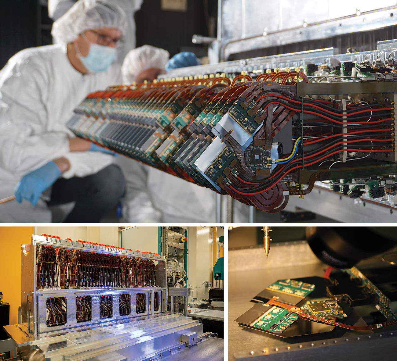
The original VELO was based on silicon-strip detectors. Its upgraded version employs silicon pixel detectors to cope with the increased occupancies at higher luminosities and to stream complete events at 40 MHz, with an expected torrent of up to 3 Tb/s flowing from the VELO at full luminosity. A total of 52 silicon pixel detector modules, each with a sensitive surface of about 25 cm2, are mounted in two detector halves located on either side of the LHC beams and perpendicular to the beam direction (see “Marvellous modules” image). An important feature of the LHCb VELO is that it moves. During injection of LHC protons, the detectors are parked at a safe distance of 3 cm from the beams. But once stable beams are declared, the two halves are moved inward such that the detector sensors effectively enclose the beam. At that point the sensitive elements will be as close as 5.1 mm to the beams (compared to 8.2 mm previously), which is much closer than any of the other large LHC detectors and vital for the identification and reconstruction of charm- and beauty-hadron decays.
The VELO’s close proximity to the interaction point requires a high radiation tolerance. This led the collaboration to opt for silicon-hybrid pixel detectors, which consist of a 200 μm-thick “p-on-n” pixel sensor bump-bonded to a 200 μm-thick readout chip with binary pixel readout. The CERN/Nikhef-designed “VeloPix” ASIC stems from the Medipix family and was specially developed for LHCb. It is capable of handling up to 900 million hits per second per chip, while withstanding the intense radiation environment. The data are routed through the vacuum via low-mass flex cables engineered by the University of Santiago de Compostela, then make the jump to atmosphere through a high-speed vacuum interface designed by Moscow State University engineers, which is connected to an optical board developed by the University of Glasgow. The data are then carried by optical fibres with the rest of the LHCb data to the event builder, trigger farm and disk buffers contained in modular containers in the LHCb experimental area.
The VELO modules were constructed at two production sites: Nikhef and the University of Manchester, where all the building blocks were delivered from the many institutes involved and assembled together over a period of about 1.5 years. After an extensive quality-assurance programme to assess the mechanical, electrical and thermal performance of each module, they were shipped in batches to the University of Liverpool to be mounted into the VELO halves. Finally, after population with modules, each half of the VELO detector was transported to CERN for installation in the LHCb experiment. The first half was installed on 2 March, and the second is being assembled.
Microchannel cooling
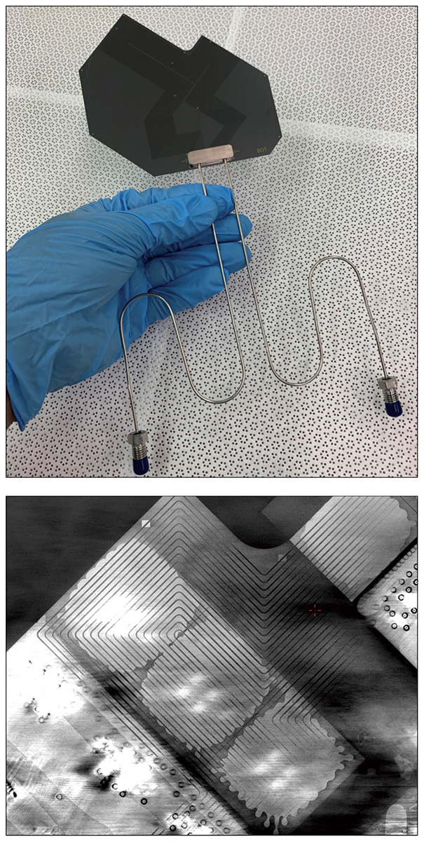
Keeping the VELO cool to prevent thermal runaway and minimise the effects of radiation damage was a major design challenge. The active elements in a VELO module consist of 12 front-end ASICs (VeloPix) and two control ASICs (GBTX), with a nominal power consumption of about 1.56 kW for each VELO half. The large radiation dose experienced by the silicon sensors is distributed highly non-uniformly and concentrated in the region closest to the beams, with a peak dose 60% higher than that experienced by the other LHC tracking detectors. Since the sensors are bump-bonded to the VeloPix chips, they are in direct contact with the ASICs, which are the main source of heat. The detector is also operated under vacuum, making heat removal especially difficult. These challenging requirements led LHCb to adopt microchannel cooling with evaporative CO2 as the coolant (see “Microcooling” image).
Keeping the VELO cool to prevent thermal runaway and minimise the effects of radiation damage was a major design challenge
The circulation of coolant in microscopic channels embedded within a silicon wafer is an emergent technology, first implemented at CERN by the NA62 experiment. The VELO upgrade combines this with the use of bi-phase (liquid-to-gas) CO2, as used by LHCb in previous runs, in a single innovative system. The LHCb microchannel cooling plates were produced at CERN in collaboration with the University of Oxford. The bare plates were fabricated by CEA-Leti (Grenoble, France) by atomic-bonding two silicon wafers together, one with 120 × 200 μm trenches etched into it, for an overall thickness of 500 μm. This approach allows the design of a channel pattern to ensure a very homogeneous flow directly under the heat sources. The coolant is circulated inside the channels through exit and entry slits that are etched directly into the silicon after the bonding step. The cooling is so effective that it is possible to sustain an overhang of 5 mm closest to the beam, thus reducing the amount of material before the first measured points on each track. The use of microchannels to cool electronics is being investigated both for future LHCb upgrades and several other future detectors.
Module assembly and support
The microchannel plate serves as the core of the mechanical support for all the active components. The silicon sensors, already bump-bonded to their ASICs to form a tile, are precisely positioned with respect to the base and glued to the microchannel plate with a precision of 30 μm. The thickness of the glue layer is around 80 µm to produce low thermal gradients across the sensor. The front-end ASICs are then wire-bonded to custom-designed kapton–copper circuit boards, which are also attached to the microchannel substrate. The ASICs’ placement requires a precision of about 100 µm, such that the length and shape of the 420 wire-bonds are consistent along the tile. High-voltage, ultra-high-speed data links and all electrical services are designed and attached in such a way to produce a precise and lightweight detector (a VELO module weighs only 300 g) and therefore minimise the material in the LHCb acceptance.
Every step in the assembly of a module was followed by checks to ensure that the quality met the requirements. These included: metrology to assess the placement and attachment precision of the active components; mechanical tests to verify the effects of the thermal stress induced by temperature gradients; characterisation of the current-voltage behaviour of the silicon sensors; thermal performance measurements; and electrical tests to check the response of the pixel matrix. The results were then uploaded to a database, both to keep a record of all the measurements carried out and to run tests that assign a grade for each module. This allowed for continuous cross-checks between the two assembly sites. To quantify the effectiveness of the cooling design, the change in temperature on each ASIC as a function of the power consumption was measured. The LHCb modules have demonstrated thermal-figure-of-merit values as low as 2–3 K cm2 W–1. This performance surpasses what is possible with, for example, mono-phase microchannel cooling or integrated-pipe solutions.
The delicate VELO modules are mounted onto two precision-machined bases, each housed within a hood (one for each side) that provides isolation from the atmosphere. The complex monolithic hoods were machined from one-tonne billets of aluminium to provide the vacuum tightness and the mechanical performance required. The hood and base system is also articulated to allow the detector to be retracted during injection and to be centred accurately around the collision point during stable beams. Pipes and cables for the electrical and cooling services are designed to absorb the approximately 3 cm motion of each VELO half without transferring any force to the modules, to be radiation tolerant, and to survive flexing thousands of times.
Following the completion of each detector half, performance measurements of each module were compared with those taken at the production sites. Further tests ensured there are no leaks in the high-pressure cooling system or the vacuum volumes, in addition to safety checks that guarantee the long-term performance of the detector. A final set of measurements checks the alignment of the detector along the beam direction, which is extremely difficult once the VELO is installed. Before installation, the detectors are cooled close to their –30°C operating temperature and the position of the tips of the modules measured with a precision of 5 µm. Once complete, each half-tonne detector half is packed for transport into a frame designed to damp-out and monitor vibrations during its 1400 km journey by road from Liverpool to CERN.
RF boxes
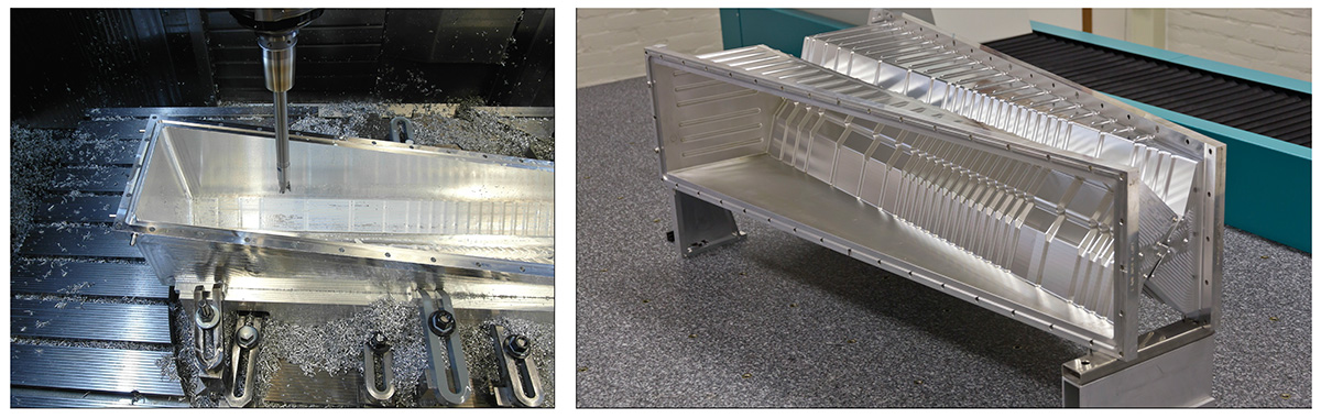
One of the most intriguing technological challenges of the VELO upgrade was the design and manufacture of the RF boxes that separate the two detector halves from the primary beam vacuum, shielding the sensitive detectors from RF radiation generated by the beams and guiding the beam mirror currents to minimise wake-fields. The sides of the boxes facing the beams need to be as thin as possible to minimise the impact of particle scattering, yet at the same time they must be vacuum-tight. A further challenge was to design the structures such that they do not touch the silicon sensors even under pressure differences. Whereas the RF boxes of LHCb’s previous VELO were made from 300 μm-thick hot-pressed deformed sheets of aluminium foils welded together, the more complicated layout of the new VELO required them to be machined from solid blocks of small grain-sized forged aluminium. This highly specialised procedure was developed and carried out at Nikhef using a precision five-axis milling machine (see “RF boxes” image).
The VELO upgrade reflects the dedication and work of more than 150 people at 13 institutes over many years
In early prototypes, micro-enclosures led to small vacuum leaks when machining thin layers. A 3D forging technique, performed by block manufacturer Loire Industrie (France), reduced the porosity of the casts sufficiently to eliminate this problem. To form the very thin sides of a box, the inside of the block was milled first. It was then positioned on an aluminium mould. The 1 mm space between box and mould was filled with heated liquid wax, which forms a strong and stable bond at room temperature. The remaining material was then machined until a sturdy flange and box with a wall about 250 μm thick remained, or just over 1% of the original 325 kg block. To further minimise the thickness in the region closest to the beams, a procedure was developed at CERN to remove more material with a chemical agent, leaving a final wall with a thickness between 150 and 200 μm. The final step was the application of a Torlon coating on the inside for electrical insulation to the sensors, and a non-evaporable getter coating on the outside to improve the beam vacuum. The two boxes were installed in the vacuum tank in spring 2021, in advance of the insertion of the VELO modules.
Let collisions commence
LHCb’s original VELO played a pivotal role in the experiment’s flavour-physics programme. This includes the 2019 discovery of CP violation in the charm sector, numerous matter–antimatter asymmetry measurements and rare-decay searches, and the recent hints of lepton non-universality in B decays. The upgraded VELO detector – in conjunction with the new software trigger, the RICH and SciFi detectors, and other upgrades – will extend LHCb’s capabilities to search for physics beyond the SM. It will remain in place for the start of High-Luminosity LHC operations in Run 4, contributing to the full exploitation of the LHC’s physics potential.
Proposed 15 years ago, with a technical design report published in 2013 and full approval the following year, the VELO upgrade reflects the dedication and work of more than 150 people at 13 institutes over many years. The device is now in final construction. One half is installed and is undergoing commissioning in LHCb, while the other is being assembled, and will be delivered to CERN for installation during a dedicated machine stop during May. The assembly and installation has been made considerably more challenging by COVID-19-related travel and working restrictions, with final efforts taking place around the clock to meet the tight LHC schedule. Everyone in the LHCb collaboration is therefore looking forward to seeing the first data from the new detectors and continuing the success of the LHC’s world-leading flavour-physics programme.
Originally considered a troublesome byproduct of particle accelerators designed to explore fundamental physics, synchrotron radiation is now an indispensable research tool across a wide spectrum of science and technology. The latest generation of synchrotron-radiation sources are X-ray free electron lasers (XFELs) driven by linacs. With sub-picosecond pulse lengths and wavelengths down to the hard X-ray range, these facilities offer unprecedented brilliance, exceeding that of third-generation synchrotrons based on storage rings by many orders of magnitude. However, the high costs and complexity of XFELs have meant that there are only a few such facilities currently in operation worldwide, including the European XFEL at DESY and LCLS-II at SLAC.
CompactLight, an EU-funded project involving 23 international laboratories and academic institutions, three private companies and five third parties, aims to use emerging and innovative accelerator technologies from particle physics to make XFELs more affordable, compact, power-efficient and performant. In the early stages of the project, a dedicated workshop was held at CERN to survey the X-ray characteristics needed by the many user communities. This formed the basis for a design based on the latest concepts for bright electron photo-injectors, high-gradient X-band radio-frequency structures developed in the framework of the Compact Linear Collider (CLIC), and innovative superconducting short-period undulators. After four years of work, the CompactLight team has completed a conceptual design report describing the proposed facility in detail.
The 360-page report sets out a hard X-ray (16–0.25 keV) facility with two separate beamlines offering soft and hard X-ray sources with a pulse-repetition rate of up to 1 kHz and 100 Hz, respectively. It includes a facility baseline layout and two main upgrades, with the most advanced option allowing the operation of both soft and hard X-ray beamlines simultaneously. The technology also offers preliminary evaluations of a very compact, soft X-ray FEL and of an X-ray source based on inverse Compton scattering, considered an affordable solution for university campuses, small labs and hospitals.
CompactLight is the most significant current effort to enable greater diffusion of XFEL facilities, says the team, which plans to continue its activities beyond the end of its Horizon 2020 contract, improving the partnership and maintaining its leadership in compact acceleration and light production. “Compared to existing facilities, for the same operating wavelengths, the technical solutions adopted ensure that the CompactLight facility can operate with a lower electron beam energy and will have a significantly more compact footprint,” explains project coordinator Gerardo D’Auria. “All these enhancements make the proposed facility more attractive and more affordable to build and operate.”
• Based on an article in Accelerating News, 4 March.
To provide the best experiences, we use technologies like cookies to store and/or access device information. Consenting to these technologies will allow us to process data such as browsing behavior or unique IDs on this site. Not consenting or withdrawing consent, may adversely affect certain features and functions.
Functional
Always active
The technical storage or access is strictly necessary for the legitimate purpose of enabling the use of a specific service explicitly requested by the subscriber or user, or for the sole purpose of carrying out the transmission of a communication over an electronic communications network.
Preferences
The technical storage or access is necessary for the legitimate purpose of storing preferences that are not requested by the subscriber or user.
Statistics
The technical storage or access that is used exclusively for statistical purposes.The technical storage or access that is used exclusively for anonymous statistical purposes. Without a subpoena, voluntary compliance on the part of your Internet Service Provider, or additional records from a third party, information stored or retrieved for this purpose alone cannot usually be used to identify you.
Marketing
The technical storage or access is required to create user profiles to send advertising, or to track the user on a website or across several websites for similar marketing purposes.


 Ezio Todesco was born in Bologna Italy, where he got a PhD in physics. In the 90’s, after a master thesis at CERN, he worked at the Italian national institute of nuclear physics (INFN) on topics related to nonlinear dynamics of particle accelerators, and long-term stability in the planned Large Hadron Collider. He joined the magnet group at CERN in 1998, and has been in charge of the field quality follow-up of the LHC main dipoles and quadrupole during the five-year-long magnet production. After the completion of the production phase, he has been in charge of the magnetic field model of the LHC, following the initial commissioning and the successive energy increases up to 13 TeV centre of mass. Then, he has been involved in the studies of the LHC luminosity upgrade, and he leads the interaction region magnets for HL-LHC since the beginning of the project in 2015.
 This webinar, presented by Frank Gerigk, will provide an overview of the LHC RF system, its superconducting cavities and RF power system. It also introduce the changes, which will be implemented to accelerate the high-intensity beams of the HL-LHC era.
 Frank Gerigk is the leader of the Radio Frequency (RF) Group at CERN. After graduating at the Technical University Berlin in 1999, he came to CERN as a fellow to work on RF and beam dynamics for linear accelerators. In 2002, he became staff member at the Rutherford Appleton Laboratory in the UK, continuing with beam dynamics and focussing on halo development in hadron beams. After his return to CERN in 2005, Frank joined the RF group and soon became responsible for the Linac4 RF cavities. He became section leader for Linac RF in 2012, and then for Superconducting RF in 2018. Since 2020 he has been leading the RF group in the new Systems Department.