Comsol -leaderboard other pages

Topics

The future looks bright for particle channelling

Radiographs using a parametric X-ray

Bent crystals

Over the past decade, the understanding of particle steering by a bent crystal lattice has progressed very well, and in particular the accelerator applications of the bent-crystal channelling technique have greatly expanded. Crystal bending and extraction of particle beams has become an established technology at high-energy accelerators, and with the approaching start-up of the Large Hadron Collider (LHC) at CERN, crystal-channelling techniques are providing further applications that are useful in the multi-tera-electron-volt range. One new application proposes bending the LHC protons (or ions) by a huge angle of 1-20 ° in the 0.45-7 TeV energy range using a bent single crystal of silicon or germanium. This would allow calibration of the calorimeters in the CMS (or ATLAS) detector in situ, using an LHC beam of precisely known energy. The simulations presented at the workshop show that such an application at the LHC is feasible. The workshop also reported results from the experiment at the Institute for High Energy Physics (IHEP), Protvino, on crystal bending of 70 GeV protons by 9 ° (150 mrad) and its application for beam delivery during 1994-2004.

At lower particle-accelerator energies, crystal channelling can be used to produce low-emittance beams useful for medical and biological applications. The success in bending beams of less than 1 GeV was reported from the Beam Test Facility of the INFN’s Laboratori Nazionali di Frascati (LNF). Here, a positron beam of about 500 MeV provides the right energy scale for using the facility as a test bench for possible future applications of crystal techniques with light ions in medical machines. This study was made possible through the support of Transnational Access to Research Infrastructure granted to LNF by the European Union as one of the major research infrastructures in Europe to give free access to researchers for the period 2004-2008. The advances in crystal micro-technology for producing micro-beams for possible future applications in radiobiology and medicine was also reported by the INFN-IHEP collaboration. This work covers the range from lower energies (kilo-electron-volts and mega-electron-volts) to higher energies (giga-electron-volts) and compares channelling techniques with alternative ones.

From Japan, a collaboration from Hiroshima University and KEK reported on an experiment on electron-beam deflection with channelling in silicon crystals at the 150 MeV electron ring of the university’s Relativistic Electron Facility for Education and Research. The group plans tests with bent crystals at KEK’s Proton Synchrotron and aims to apply crystal deflection of high-energy beams at the Japan Proton Accelerator Research Centre, the 50 GeV high-intensity proton machine currently under construction in Japan.

Undulators and targets

While bent (and also focusing) crystals are well-known tools in accelerators, crystal undulators are just being introduced into experiments. Channelling undulators offer sub-millimetre periods and magnetic fields of the order of 1000 T. Samples of crystal undulators have already been manufactured and tested with X-rays and in channelling proton beams. Now tests using positron beams have been started at IHEP Protvino and at CERN’s Super Proton Synchrotron, and are also planned at LNF. The first data from the experiment on positron radiation in a crystal undulator at IHEP were presented at the workshop.

The Yerevan Physical Institute presented calculations on radiation produced by 20 MeV electrons channelled in the crystallographic planes of quartz, both with and without periodic deformations. The institute also plans experiments to study the influence of external fields on channelling radiation.

Intense positron sources using crystal effects are another application of strong coherent fields. A number of talks reported on the theories of coherent radiation and pair production in ordered matter, and CERN’s WA103 collaboration reviewed the experimental progress in the field. The KEK-Tokyo-Tomsk-Paris collaboration reported a study of positron production from a thick silicon-crystal target using 8 GeV channelling electrons with high bunch charges.

For the future, many interesting directions are foreseen in the field

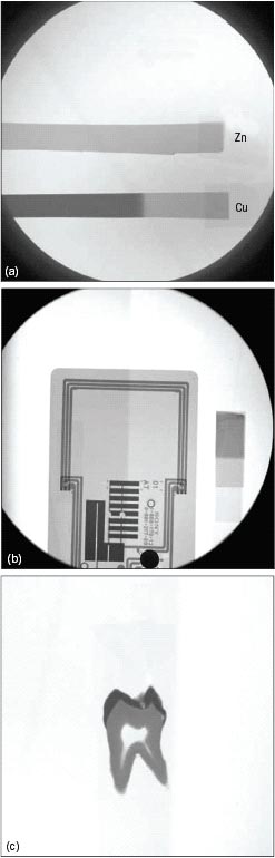
The workshop marked two decades since the experimental discovery of parametric X-ray radiation (PXR) in Tomsk in 1985: the radiation is generated by the motion of electrons inside a crystal, such that the energy intensity of the radiation depends on the parameters of the crystal structure. PXR has since been a subject of experimental and theoretical research and possible applications at accelerators, and was a subject in many talks at the workshop. A team working at Nuclotron at the Joint Institute for Nuclear Research in Dubna has reported the first observation of PXR from moderately relativistic nuclei in crystals. A nice example of an application is a tunable monochromatic X-ray source based on PXR developed at the Laboratory for Electron Beam Research and Application in Nihon University, Japan. So far the main use of the X-rays there has been in radiography for biological samples such as teeth or bones (figure 1). The contrast of the images was controlled with precise changes of the X-ray energy, a great advantage of a system that uses a PXR beam.

For the future, many interesting directions are foreseen in the field. A great deal of effort worldwide is being put into crystal radiation research and applications. Further progress is expected in applications using bent crystals for beam steering at accelerators. It will be an ideal opportunity to take full advantage of the channelling-crystal potentialities at the LHC and other high-energy accelerators, making crystals to serve for both collimation and extraction. The opportunity to have an extracted beam at a multi-tera-electron-volt machine should stimulate more research at the highest energies into particle interactions with aligned atomic lattices. The first crystal-channelling undulators and their initial tests with positron beams should proceed to the realization of novel radiation sources; thus, new positron-channelling experiments on undulator radiation are eagerly awaited.

The success of the workshop is reflected both in the level of participation, with around 40 specialists coming from different geographical areas, such as Europe, Japan and the former USSR, and in the high quality of the presentations. The resulting papers will be published as a special issue of Nuclear Instruments and Methods B, covering nearly all topics of current interest in channelling and radiation in aligned periodic structures at relativistic energies.

NSRRC operates in top-up mode

On 12 October the National Synchrotron Radiation Research Center (NSRRC), Taiwan, became the fourth synchrotron facility in the world to operate fully in top-up mode, joining the Swiss Light Source (SLS), the Advanced Photon Source (APS) in the US, and SPring-8 in Japan. While the SLS and APS were originally designed to operate in top-up mode, the NSRRC is an example of how a third-generation synchrotron accelerator that previously operated in decay mode can successfully advance to full top-up operation.

CCEnew2_12-05

In top-up mode, the storage ring is kept full by frequent injections of beam, in contrast with decay mode, where the stored beam is allowed to decay to some level before refilling occurs. Top-up operation has the advantage for light-source users that the photon intensity produced is essentially stable. This provides valuable gains in usable beamtime for experiments, and significantly shortens the time for optical components in beamlines to achieve thermal equilibrium.

The upgrade to top-up mode at the NSRRC, which started in 2003, included improvement to kickers, the addition of various diagnostic instruments, a redesign of radiation safety shielding, modification of control software, and a revised operation strategy for the injector and booster. In parallel a more powerful superconducting radio-frequency cavity was installed and commissioned in November 2004, as part of a five-year programme. This has prepared the NSRRC to serve its users in biology and genomic medicine.

The injection chain at the NSRRC consists of a 140 keV electron gun, a 50 MeV linac and a 1.5 GeV booster that sends the beam into the storage ring at a rate of 10 Hz. With the upgrade, the time interval between two injections is now set to 2 min, while previously, in decay mode, it was every 6 h. The stored beam current has initially been maintained at 200 mA with approximately 0.6 mA per current bin and photon stability in the range of 10-3 to 10-4. As experience is gained, the current will gradually be increased up to the 400 mA maximum allowed by the new superconducting RF in the storage ring.

As a user-driven facility, NSRRC chose the fixed time interval injection mode rather than fixed current bin to reduce interference with data-acquisition processes. Since early 2005, the operational division has informed beamline managers of the new characteristics of the beam’s time cycle, injection perturbations and top-up status. Users thus have access to enough information to conduct their experiments successfully.

During the transition period, special attention was paid to finding a reproducible filling pattern through optimizing and fine-tuning a variety of parameters. Other tasks included mastering the timing jitters of injection components, launching position and angle, as well as understanding the horizontal acceptance of the ring. These are some of the key determinants of injection efficiency.

The overall programme, led by NSRRC director Chien-Te Chen, now allows students from more than 60 universities access to beamtime allocated on one of 27 beamlines. These include two at SPring-8 Japan that are owned by the NSRRC. The NSRRC itself supported more than 3000 user-runs in 2005, 20% more than in 2004.

SNS reaches major milestone on journey to completion next June

The Spallation Neutron Source (SNS) at the Oak Ridge National Laboratory (ORNL) of the US Department of Energy (DOE) has met a crucial milestone on its way to completion in June 2006 – operation of the superconducting section of the linear accelerator. The SNS will produce neutrons by accelerating a pulsed beam of high-energy H ions down a 300 m linac, compressing each pulse to high intensity, and delivering them to a liquid mercury target where neutrons are produced in a process known as spallation.

CCEnew3_12-05

The SNS linac is the world’s first high-energy, high-power linac to apply superconducting technology to the acceleration of protons. It has two sections: a room-temperature section, for which beam commissioning was completed last January, and a superconducting section, which operates at 2 K (or recently as high as 4.2 K). The cold linac provides the bulk of the acceleration and has already achieved a beam energy of 912 MeV, or 91% of the linac’s design energy of 1  GeV.

Although the superconducting cavities are designed to operate at 2 K, much of the beam commissioning was performed at 4.2 K, with minimal loss in cavity performance – an unexpected outcome. Compared with the design intensity of 1.6 × 1014 H ions per pulse, beam pulses as high as 8 × 1013 ions per pulse were accelerated at repetition rates of up to 1 Hz (compared with the 60 Hz design), limited by the power capability of the 7.5 kW commissioning beam dump. All basic beam parameters were verified without any major surprises and transverse beam profiles were measured using a newly developed laser-profile measurement system that is noninvasive and unique to this H ion linac.

Six DOE national laboratories are collaborating on this DOE Office of Science project. Thomas Jefferson National Accelerator Facility in Virginia was responsible for the superconducting linac and its refrigeration system while Los Alamos National Laboratory in New Mexico provided the radio-frequency systems that drive the linac. The other laboratories are Argonne, Berkeley and Brookhaven.

During its first two years of operation, the SNS will increase the intensity of pulsed neutrons available to researchers nearly tenfold compared with existing facilities, providing higher-quality images of molecular structure and motion. Together, ORNL’s High Flux Isotope Reactor and the SNS will represent the world’s foremost facilities for neutron scattering, a technique the laboratory pioneered shortly after the Second World War.

LEIR gets ions on course for the LHC

On 10 October, at the very first attempt, a beam travelled round the Low Energy Ion Ring (LEIR) at CERN. LEIR is a central part of the injector chain to supply lead ions to the Large Hadron Collider (LHC) from 2008. It will transform long pulses from Linac 3 into short and dense bunches for the LHC.

The following day, after only 1 h of tuning, the beam circulated for about 500 ms per injection. The RF cavities were not yet in operation, so the beam was lost at the end of the injection plateau. The beam used consisted of O4+ ions, which have a longer lifetime than lead ions; work with lead ions will begin at a later stage.

After the installation of a new ion source built by a team from the Low Temperatures Department of the French Atomic Energy Commission (CEA/DRFMC/SBT) in Grenoble at the beginning of 2005, final work on installing LEIR took place in the summer. Now the aim is to improve understanding of the accelerator’s behaviour and to optimize the ion beam. In addition, the new electron-cooling system, developed and manufactured in collaboration with the Budker Institute of Nuclear Physics in Novosibirsk, is to be commissioned. This should reduce the beam dimensions, making it possible to accumulate several pulses from Linac 3.

A magnetic memorial to decades of experiments

CCEmag1_12-05

This is the simple story of a magnet, albeit a rather special one, which is celebrating its 45th birthday at CERN this year. It is somewhat surprising that it has survived! It lives out a peaceful retirement at the far end of the site, as befits a senior magnet that can claim to have fathered a family sharing the same aim.

The magnet came to CERN as the heart of the first g-2 experiment, the aim of which was to measure accurately the anomalous magnetic moment, or g-factor, of the muon. This experiment was one of CERN’s outstanding contributions to physics, and for many years was unique to the laboratory. Indeed, three generations of the experiment were performed at CERN during its first 25 years.

At present the best determined value of g for the muon is 2.0011659208 (Bennett et al. 2004). Clearly one is trying to measure to very high precision a number that is very close to two. The elegance of the experimental method, which uses physics to measure g-2 directly through a determination of frequency (hence facilitating precision measurement), has attracted experimentalists for more than five decades. In addition this parameter has, with considerable reason, fascinated theorists over the same period and continues to be a rare target where experiment can test theory to the limit of its precision.

The purchase of this first 6 m-long g-2 magnet was agreed by the CERN Finance Committee on 14 November 1959, and the magnet was delivered by Oerlikon of Switzerland on 11 July 1960 (figure 1). But was this really the first g-2 magnet, and why was it of this form?

Before 1960 there were a number of experiments, and a list of outstanding names, each of which contributed their piece of the puzzle. If one piece is to be singled out, it must be the establishment of parity non-conservation in the pion-muon-electron decay sequence by the experiments of Richard Garwin, Leon Lederman and Marcel Weinrich, and by Jerome Friedman and Valentine Telegdi (Garwin et al. 1957; Friedman and Telegdi 1957). In this way, two fundamental, enabling “gifts of nature” became known: the muons are born 100% polarized in the pion rest frame, and the asymmetry of the angular distribution of the electrons emitted in their subsequent decay enables the polarization of the muon sample to be traced as a function of time (Combley et al. 1981).

The stage was thus set for a direct attack on the magnetic-moment anomaly for muons. The team that assembled was more than noteworthy with, in alphabetic order, Georges Charpak, Francis Farley, Richard Garwin, Theo Muller, Johannes Sens and Antonino Zichichi (figure 2). The design of their experiment fully exploited the initial muon polarization and final decay electron asymmetry through the idea that it should be possible to store muons in a conventional bending magnet that provided an approximately uniform vertical field.

CCEmag2_12-05

The magnet was installed in a longitudinally polarized beam of positive muons, arising from the decay of pions produced by CERN’s 600 MeV synchrocyclotron (SC). The magnetic field was arranged in such a way that the muons, introduced at one end of the magnet, were stored in circular orbits that moved along the magnet until they exited at the far end into the analyser; there they decayed, emitting an electron as a sign of polarization. Figure 3 shows how these orbits were suitably spaced (2 cm/turn) for capture upon entry to the magnet; then bunched closely together (0.4 cm/turn) in the centre for maximum storage times; and lastly spread out (11 cm/turn) at the end to eject the muons into the analyser. Some clever work was needed to add carefully calculated shims in order to create the very special magnetic field. Figure 4 illustrates the work of shimming the magnet and preparation in the halls of the SC.

CCEmag3_12-05

In the subsequent experiment much thought and care went into reducing systematic errors, with a result of g = 2.001165±5 sent for publication only six months after the magnet was delivered (Charpak et al. 1961). The result agreed rather well with the theoretical value current at the time, g = 2.001165.

CCEmag4_12-05

In such a short article there is no intention to make a comprehensive review of g-2 physics or experiments. This has been done exceedingly well by others, notably in the recent review article by Francis Farley and Yannis Semertzidis (Farley and Semertzidis 2004). The two subsequent generations of g-2 experiments at CERN were both real storage rings and allowed for higher muon energies and longer lifetimes. They permitted measurements of g-2 over many more frequency cycles, which increased the precision considerably.

One name among many in these two generations of experiments is that of Emilio Picasso, who became interested in g-2 as of 1963, when he was at Bristol and Cecil Powell urged him to work with Farley on theoretical calculations of the g-factor. (My own interest in g-2 was also triggered by Powell.) Picasso went on to lead the third-generation experiment and later the construction of a much bigger storage ring, the Large Electron-Positron Collider. The g-2 experiments moved to the US as of 1983 and have continued the battle at Brookhaven. Of the original pioneers at CERN, Farley still continues to be involved.

CCEmag5_12-05

The first g-2 magnet at CERN – the focus of this article – can still be found at the far end of the Meyrin site. It is partially disassembled, a little battered and those clever shims have disappeared, but fundamentally it still looks the same as in the pictures of 1960. Luckily no over-enthusiastic administrator has seen fit to scrap this monument to CERN history; perhaps there was a wise guardian angel who knew the magnet’s value. The physics principles of the g-2 experiments are of a rare elegance and the essential parts could be explained to visitors on one panel. Is it not time to give a new lease of life to this 45-year-old magnet as the focus of a new historical exhibit at CERN?

How CERN keeps its cool

Cryogenics at CERN has now reached an unprecedented scale. When the Large Hadron Collider (LHC) starts up it will operate the largest 1.8 K helium refrigeration and distribution systems in the world, and the two biggest experiments, ATLAS and CMS, will deploy an impressive range of cryogenic techniques. However, the use of cryogenics at CERN, first in detection techniques and later in applications for accelerators, dates back to some of the earliest experiments.

The need for cryogenics at CERN began in the 1960s with the demand for track-sensitive targets – bubble chambers – that contained up to 35 m3 of liquid hydrogen, deuterium or neon/hydrogen mixtures. These devices required cryogenic systems on an industrial scale to cool down to a temperature of 20 K. For more than a decade they were a major part of CERN’s experimental physics programme. At the same time, cryogenic non-sensitive targets were used in other experiments. Over the past 30 years some 120 such targets have been constructed, ranging in size from a few cubic centimetres to about 30 m3 and usually filled with liquid hydrogen or deuterium, again requiring cooling to 20 K.

Cool targets, cool detectors

At the smallest scale, the demand from the fixed-target programme for polarized targets at very low temperatures led to the development of dilution refrigerators at CERN in the 1970s (figure 1). Going below the range of helium-3 evaporating systems, these require small-scale but highly sophisticated cryogenic techniques.

CCEhow1_12-05

Polarized targets remain very much part of the current physics programme at CERN, where the COMPASS experiment uses solid targets made of ammonia or lithium deuteride. The basic method for obtaining a high polarization of the nuclear spins in the targets is the dynamic nuclear polarization process. This uses microwave irradiation to transfer to the nuclei the almost complete polarization of electrons that occurs at low temperatures (less than 1 K) and in a high magnetic field (2.5 T), generated by a superconducting solenoid.

On a larger scale, in detector technology the development in the 1970s of sampling ionization chambers – calorimeters – broadened the demand for low temperatures at CERN. Using liquid argon to measure the energy of ionizing particles, these detectors required cryogenic systems to cool down to 80 K. Several calorimeters, with typical volumes of 2-4 m3, were built in this period, both for fixed-target experiments and use at CERN’s first collider, the Intersecting Storage Rings (ISR) – which was also the world’s first proton collider.

Two decades later, in 1997, the NA48 experiment extended the technique from argon to krypton. With its very high density, liquid krypton not only provides the “read out” through the ionization of the liquid by charged particles, but also acts as a passive particle absorber, so avoiding the use of a material such as lead or uranium. The cooling fluid for this detector is saturated with liquid nitrogen and the heat is extracted by re-condensing the evaporated krypton via an intermediate bath of liquid argon, which in turn feeds the 10 m3 liquid-krypton cryostat by gravity.

Around the same time as the development of the first liquid-argon calorimeters, experiments began to require helium cryogenics, mainly at 4.5 K, for superconducting magnets. These were used to analyse particle momenta in magnetic spectrometers. The largest built for the fixed-target programme at CERN was the superconducting solenoid constructed for the Big European Bubble Chamber (BEBC) in the 1970s (figure 2). This had an internal diameter of 4.7 m and produced a field of 3.5 T. The associated combined He/H2 refrigeration system had a cooling capacity of 6.7 kW at 4.5 K.

CCEhow2_12-05

With the advent of the Large Electron-Positron (LEP) collider at the end of the 1980s, collider experiments took on a much greater role at CERN. Two of the LEP experiments, ALEPH and DELPHI, opted for large superconducting solenoids for momentum analysis – the choice between superconducting and normal (resistive) magnets depending on considerations related to “transparency” (to particles) and/or economy. Each of these solenoids required a helium cooling system of 800 W at 4.5 K.

A current novel application for a superconducting magnet occurs in the CAST experiment located on the surface above the cavern where the DELPHI experiment for LEP was installed. This uses a 10 m, 9.5 T prototype LHC superconducting dipole and also makes use of the DELPHI refrigerator to cool the superfluid helium cryogenic system for the magnet. The aim of the experiment is to detect axions, a possible candidate particle for dark matter that could be emitted by the Sun, through their production of photons in the dipole’s magnetic field.

Now, however, the major effort at CERN is focused on the LHC, with four big experiments: ALICE, ATLAS, CMS and LHCb. Basic design criteria led the two largest experiments, ATLAS and CMS, to construct superconducting spectrometers of unprecedented size, while ALICE and LHCb opted for resistive magnets.

CCEhow3_12-05

ATLAS has several components for its magnetic spectrometry. A “slim” central solenoid (with a length of 5.3 m, a 2.4 m inner diameter and a 2 T field) is surrounded by a toroid consisting of three separate parts – a barrel and two end-caps. The overall length of the toroid is 26 m, with an external diameter of 20 m (figure 3). It is powered up to 20 kA and has a stored energy of 1.7 GJ. CMS, by contrast, is built around a single large solenoid, 13 m long, with an inner diameter of 5.9 m and a uniform field of 4 T (figure 4). When powered up to 20 kA it has a stored energy of 2.6 GJ.

CCEhow4_12-05

ATLAS also has a cryogenic electromagnetic calorimeter, with the largest liquid-argon ionization detector in the world to measure the energy of electrons and photons. This consists of a cylindrical structure made of a barrel and two end-caps, with a length of 13 m and an external diameter of 9 m. Altogether, the cryostats for the three sections contain 83 m3 of liquid argon and operate at 87 K.

Both ATLAS and CMS have refrigerating plants that are independent from the system required to cool the LHC to 1.8 K (see below). ATLAS will use two helium refrigerators and one nitrogen refrigerator, while CMS will have a single helium refrigerator. These will provide cooling for current leads and thermal shields, as well as for the refrigeration at 4.5 K for the spectrometer magnets, and in the case of ATLAS also at 84 K for the electromagnetic calorimeter.

Cool accelerators

The use of helium cryogenics was extended to accelerator technology at CERN during the 1970s, when superconducting radiofrequency beam separators were constructed for the Super Proton Synchrotron, and superconducting high-luminosity insertion quadrupoles were built for use at the ISR. These required cooling of 300 W at 1.8 K and 1.2 kW at 4.5 K, respectively. The 1990s saw the larger scale use of cryogenics for accelerators with the upgrade of LEP to higher energies.

LEP was built initially with conventional copper accelerating cavities, but with the successful development of 350 MHz superconducting cavities in 1980s, its energy could be doubled. As many as 288 superconducting cavities were eventually installed, increasing the energy from 45 to 104 GeV per beam (figure 5). This involved the installation of the first very large capacity helium refrigerating plant at CERN, with four units each of a capacity of 12 kW at 4.5 K, later upgraded to 18 kW, supplying helium to eight 250 m long strings of superconducting cavities, and a total helium inventory of 9.6 tonnes.

CCEhow5_12-05

LEP was closed down at the end of 2000 to make way for the construction of the LHC in the same tunnel. This liberated most of the existing cryogenic infrastructure from LEP for further use and upgrading for the LHC, which will require the largest 1.8 K refrigeration and distribution system in the world to cool some 1800 superconducting magnet systems distributed around the 27 km long tunnel. A total of 37,500 tonnes has to be cooled to 1.9 K, requiring about 96 tonnes of helium, two-thirds of which is used for filling the magnets.

Although normal liquid helium at 4.5 K would be able to cool the magnets so that they become superconducting, the LHC will use superfluid helium at the lower temperature of 1.8 K to improve the performance of the magnets. The magnets are cooled by making use of the very efficient heat-transfer properties of superfluid helium, and kilowatts of refrigeration power are transported over more than 3 km with a temperature difference of less than 0.1 K.

The LHC is divided into eight sectors, and each will be cooled by a two-stage cryoplant consisting of a 4.5 K refrigerator coupled to a 1.8 K refrigeration unit. The transport of the refrigeration capacity along each sector is made by a cryogenic distribution line, which feeds the machine every 107 m. A cryogenic interconnection box will link the 4.5 K and 1.8 K refrigerators and the distribution line. Together the refrigerators will provide a total cooling power of 144 kW at 4.5 K and 20 kW at 1.8 K. The 4.5 K refrigerators are equipped with a 600 kW liquid-nitrogen precooler, which will be used to cool down the corresponding LHC sector to 80 K in less than 10 days.

Four new 4.5 K refrigerators built by two industrial companies have been in place since the end of 2003, and four 4.5 K refrigerators recovered from LEP are being upgraded for use at the LHC. In addition, eight 1.8 K refrigerator units procured from industry provide the final stage of cooling (figures 6 and 7). Four 1.8 K units built by one company have already been installed; the other four units, made by the other company, are currently being installed and will be tested in 2006.

CCEhow6_12-05

For the next 15 years or so, CERN will need to continue to provide strong support in cryogenics for its unique accelerator facilities, including the final consolidation and operation of the LHC. Further long-term perspectives will depend a great deal on the next generation of accelerators. Detectors, on the other hand, have proved quantitatively less demanding for cryogenics in comparison with the accelerators; however, over the years their cryogenic needs have generated a variety of different applications, with a temperature range from 130 K (liquid-krypton calorimeters) down to a few tenths of a millikelvin for polarized targets. Innovation in detector technology has often in the past led to the application of cryogenics – a trend that will no doubt continue into the future.

CCEhow7_12-05

• This article is based on: G Passardi and L Tavian 2002 Cryogenics at CERN Proceedings of the 19th International Cryogenic Engineering Conference (ICEC 19); L Tavian 2005 Latest developments in cryogenics at CERN Proceedings of the 20th National Symposium on Cryogenics, Mumbai (TNSC 20).

The dark side of computing power

On a recent visit to CERN, I had the chance to see how the high-energy physics (HEP) community was struggling with many of the same sorts of computing problems that we have to deal with at Google. So here are some thoughts on where commodity computing may be going, and how organizations like CERN and Google could influence things in the right direction.

CCEvie1_11-05

First a few words about what we do at Google. The Web consists of more than 10 billion pages of information. With an average of 10 kB of textual information per page, this adds up to around 100 TB. This is our data-set at Google. It is big, but tractable – it is apparently just a few days’ worth of data production from the Large Hadron Collider. So just like particle physicists have already found out, we need a lot of computers, disks, networking and software. And we need them to be cheap.

The switch to commodity computing began many years ago. The rationale is that single machine performance is not that interesting any more, since price goes up non-linearly with performance. As long as your problem can be easily partitioned – which is the case for processing Web pages or particle events – then you might as well use cheaper, simpler machines.

But even with cheap commodity computers, keeping costs down is a challenge. And increasingly, the challenge is not just hardware costs, but also reducing energy consumption. In the early days at Google – just five years ago – you would have been amazed to see cheap household fans around our data centre, being used just to keep things cool. Saving power is still the name of the game in our data centres today, even to the extent that we shut off the lights in them when no-one is there.

Let’s look more closely at the hidden electrical power costs of a data centre. Although chip performance keeps going up, and performance per dollar, too, performance per watt is stagnant. In other words, the total power consumed in data centres is rising. Worse, the operational costs of commercial data centres are almost directly proportional to how much power is consumed by the PCs. And unfortunately, a lot of that is wasted.

For example, while the system power of a dual-processor PC is around 265 W, cooling overhead adds another 135 W. Over four years, the power costs of running a PC can add up to half of the hardware cost. Yet this is a gross underestimate of real energy costs. It ignores issues such as inefficiencies of power distribution within the data centre. Globally, even ignoring cooling costs, you lose a factor of two in power from the point where electricity is fed into a data centre to the motherboard in the server.
Since I’m from a dotcom, an obvious business model has occurred to me: an electricity company could give PCs away – provided users agreed to run the PCs continuously for several years on the power from that company. Such companies could make a handsome profit!

A major inefficiency in the data centre is DC power supplies, which are typically about 70% efficient. At Google ours are 90% efficient, and the extra cost of this higher efficiency is easily compensated for by the reduced power consumption over the lifetime of the power supply.

Part of Google’s strategy has been to work with our component vendors to get more energy-efficient equipment to market earlier. For example, most motherboards have three DC voltage inputs, for historical reasons. Since the processor actually works at a voltage different from all three of these, this is very inefficient. Reducing this to one DC voltage produces savings, even if there are initial costs involved in getting the vendor to make the necessary changes to their production. The HEP community ought to be in a similar position to squeeze extra mileage out of equipment from established vendors.

Tackling power-distribution losses and cooling inefficiencies in conventional data centres also means improving the physical design of the centre. We employ mechanical engineers at Google to help with this, and yes, the improvements they make in reducing energy costs amply justify their wages.

While I’ve focused on some negative trends in power consumption, there are also positive ones. The recent switch to multicore processors was a successful attempt to reduce processors’ runaway energy consumption. But Moore’s law keeps gnawing away at any ingenious improvement of this kind. Ultimately, power consumption is likely to become the most critical cost factor for data-centre budgets, as energy prices continue to rise worldwide and concerns about global warming put increasing pressure on organizations to use electrical power more efficiently.

Of course, there are other areas where the cost of running data centres can be greatly optimized. For example, networking equipment lacks commodity solutions, at least at the data-centre scale. And better software to turn unreliable PCs into efficient computing platforms can surely be devised.

In general, Google’s needs and those of the HEP community are similar. So I hope we can continue to exchange experiences and learn from each other.

LHC project passes several milestones

Progress on the construction of the Large Hadron Collider (LHC) at CERN has passed several important milestones in recent weeks. In mid-September the first 600 m of the cryogenic distribution line that will supply superfluid helium to the superconducting magnets passed initial testing at room and cryogenic temperatures. At the same time, the number of magnets installed in the tunnel passed the 100 mark, and several major contracts related to their construction have been successfully completed.

CCEnew1_11-05

The tests of the cryogenic line, which were the first to be implemented at close to the eventual operating conditions in the LHC tunnel, took place in sector 7-8. This is where technical problems were discovered during the initial installation in summer 2004, so that the system had to be redesigned, repaired and reinstalled.

CCEnew2_11-05

After several days of testing and cleaning at room temperature, the cool-down itself took 15 hours. This is a two-stage process using a 4.5 K helium refrigerator and a nitrogen pre-cooler. After the initial 10 hours of cool-down, the system reached the first temperature plateau of 80 K. Then, by the evening of 14 September, the cryogenic line had been brought down to around 5 K, about 3 K above the eventual operating temperature. The complete cold-commissioning process takes about five weeks. Once the thermal design has been validated, the magnets can then be connected to the cryogenic line.

Meanwhile, by the end of September, 102 of the LHC’s 1232 superconducting dipoles had been put in position in the tunnel. At the same time one of the most important contracts for the LHC had successfully concluded, with the supply of all 7000 km of the superconducting cable that forms the heart of the machine’s magnets. This cable has been provided by four companies in Europe – Alstom-MSA (France), EAS (Germany), Outokumpo (Finland/Italy) – Furukawa in Japan and OKAS in the US.

This was the latest in a series of contracts for the LHC that have recently come to completion. At the end of May, Belgian firm Cockerill Sambre of the Arcelor Group cast the last batch of steel sheets for the superconducting magnet yokes, which constitute around 50% of the accelerator’s weight. This was the first major contract to be concluded for the LHC; worth 60 million Swiss francs, it was signed just after CERN Council approved the LHC project in December 1996.

October saw the completion of the 60 km of vacuum pipes for the LHC beams by a single firm, DMV of Bergamo, Italy. These 16 m long pipes, made from austenitic steel, had to be continuously extruded and had to contain not a single weld in order to ensure perfect leak tightness between the vacuum inside and the superfluid helium outside. In the first week of September, the last rolls of austenitic steel for the collars of the dipole magnets arrived at CERN from NSSC (Nippon Steel) in Japan. The collars are designed to contain most of the magnetic forces created in the eight layers of superconducting coil that provide the magnetic field.

The production of the collared coils is also well on track. On 8 August Babcock Noell Nuclear (BNN) delivered their last collared coil, completing their contract for one-third of the dipole magnet coils. The contracts with the two other suppliers will also come to an end during the autumn of 2006.

Silicon trackers begin to take shape for CMS and ATLAS

Over the past few months the silicon microstrip tracker of the CMS experiment has been making steady, and rapid, progress towards meeting its next major target – installation of the complete detector in its site at intersection point 5 on the Large Hadron Collider in November 2006.

CCEnew3_11-05

This has been especially encouraging to the CMS collaboration as the past year has seen significant problems with relatively small details in a few key components, delaying the assembly of modules and their subsequent integration into the mechanical superstructure. However, these problems have now been overcome and the subsequent assembly speed of several inner layers of the tracker has demonstrated the readiness of the teams of engineers and physicists, who had used some of the time during the pauses to refine their procedures.

CCEnew4_11-05

The CMS tracker will be the largest silicon system ever built, with more than 200 m2 of silicon microstrips surrounding three layers of pixel detectors in a cylindrical barrel-like layout, with end-caps completing the tracking in the forward and backward regions. The construction involves teams from all over Europe and the US, who have developed components and pioneered automated techniques to manufacture modules that must withstand the stringent conditions at the heart of the CMS.

The inner barrel (see cover picture) is the responsibility of an Italian consortium. The delivery of the first half to CERN is expected this month, followed by the second half in January 2006. While tests begin on the inner barrel in a brand new integration facility, which is currently being erected at CERN, it will be joined by, and later inserted inside, the outer barrel system. This is largely the responsibility of CERN, and consists of modules arranged in rods that are being manufactured in the US by teams who have experience from Fermilab experiments. The two end-caps will complete the assembly in mid-2006; one will be built by a French team in the facility at CERN, the other by a German team in Aachen.

The remaining off-detector electronics and cooling systems are also beginning to arrive at CERN. These will allow the completed tracker to be studied for several months before it is moved to its final underground location at the centre of the CMS. Once in operation it will provide precise radiation-hard tracking for many years.

Meanwhile, September saw an important milestone for the ATLAS inner detector project with the delivery of the fourth and final Semiconductor Tracker (SCT) barrel to CERN. A few days after delivery, on 20 September, the barrel was integrated into the final configuration of the full barrel assembly.

The SCT has a silicon surface area of 61 m2 with about six million channels and is part of the ATLAS inner detector, where charged tracks will be measured with high precision. More than 30 institutes from around the world have contributed to building the component parts and structure of the SCT.

Moving outwards from the interaction region, the ATLAS inner detector comprises the pixel detector (consisting of three pixel layers), the SCT (four silicon strip layers) and the transition radiation tracker, or TRT (consisting of about 52,000 straw tubes).

During 2004 a team of physicists, engineers and technicians from several SCT institutes set up one of the largest silicon quality-assurance systems ever built (corresponding to about 15% of the final ATLAS readout system), which was capable of analysing the performance of one million sensor elements on nearly 10 m2 of silicon detectors simultaneously. Using this system to test barrels prior to their integration, the team found that more than 99.6% of the SCT channels were fully functional, an exceptionally good performance that exceeded specifications. The work is taking place in the SR1 facility at CERN, which was purpose-built by the ATLAS inner detector collaboration and houses a 700 m2 cleanroom.

This month the ATLAS inner detector teams will integrate the silicon tracker with the barrel TRT and test their combined operation in SR1. At the end of this year the SCT end-caps will arrive at CERN, and then be inserted into the TRT end-caps during spring 2006. In March 2006 the inner detector team will then place the barrel inner tracker in a steel frame and transport it to the ATLAS underground cavern. The entire integration process is scheduled to be finished at the end of 2006, when the all-important pixel detector will be inserted in the tracker.

The whole assembly of the inner detector will sit in the 2 T magnetic field of the central superconducting solenoid, which has a diameter of about 2.5 m. This will deflect the tracks of charged particles passing through the inner detector. The much larger air toroid magnet system (see CERN Courier cover picture September 2005) is to deflect the tracks of muons, which penetrate to the outer reaches of the huge ATLAS detector.

Barish presents plans for the ILC

The schedule of the Global Design Effort (GDE) for the future International Linear Collider (ILC) was an important topic at the meeting in September of CERN’s Scientific Policy Committee. Barry Barish, head of the GDE, presented a report on the progress made since the International Technology Review Panel announced the technology choice for the ILC in August 2004.

CCEnew6_11-05

Since the first ILC workshop, which was held at KEK in November 2004, work has been progressing towards a reference design. This year a second workshop was held in August at Snowmass in the US to refine the ideas. The reference design should be completed by the end of 2006, to be followed by a technical design report two years later. By 2010 the technical design report, together with the scientific results from the Large Hadron Collider and input from the CLIC Test Facility (CTF3) at CERN, will allow a decision on the future of the ILC.

bright-rec iop pub iop-science physcis connect