Brookhaven National Laboratory (BNL) on Long Island, New York, has been selected as the site for the planned Electron-Ion Collider (EIC). The decision, announced by the US Department of Energy (DOE) on 9 January, will see the laboratory’s Relativistic Heavy-Ion Collider (RHIC) reconfigured to include a new electron storage ring to facilitate electron-ion collisions. Scheduled to enter operation at the end of the decade, the new electron-ion collider will pivot BNL’s physics focus from the study of the quark-gluon plasma to nuclear femtography.
BNL has edged out competition to host the EIC from the Thomas Jefferson National Accelerator Facility (JLab) in Virginia, which boasts the recently upgraded Continuous Electron-Beam Accelerator Facility (CEBAF). Under the JLab proposal, CEBAF would have been augmented with a new heavy-ion accelerator. JLab is now expected to be a major partner in the project and take the lead in aspects of accelerator R&D. The project is foreseen to cost between $1.6bn and $2.6bn, with first physics planned in 2029 or 2030, following the completion of RHIC’s science programme at the STAR and newly upgraded sPHENIX experiments. “Our plan, working with the DOE Office of Nuclear Physics, remains unchanged,” says BNL’s associate laboratory director for nuclear and particle physics Berndt Mueller: “to complete the RHIC science mission by bringing sPHENIX into operation for three years of data taking.”
Nuclear femtography
EIC will perform precision “nuclear femtography” by zeroing in on the substructure of quarks and gluons in heavy ions using collisions with high-energy electrons, in a comparable manner to the seminal studies of the proton using electron-proton collisions at DESY’s HERA accelerator between 1992 and 2007. While HERA ran at a centre-of-mass energy of 318 GeV, the EIC will operate from 20 to 140 GeV. “The upper centre-of-mass energy limit is chosen to be sufficient for access to the predicted gluon saturation regime in electron-heavy nucleus collisions,” says Mueller, referring to the state known as a colour-glass condensate, a nonlinear regime of quantum chromodynamics where the rate of gluon recombination rivals that at which gluons are radiated. “The lower centre-of-mass energy limit is optimised for the three-dimensional imaging of quark and gluon distributions in the proton and other nuclei, which will utilise the much higher luminosity projected for the EIC compared to HERA,” continues Mueller. “If required by the evolving physics programme, the energy range of the BNL EIC could be raised in the future, for example by increasing the strength of the magnets in the hadron ring.”
The lower energy limit is optimised for the three-dimensional imaging of quark and gluon distributions
Berndt Mueller
The selection of BNL allows work to begin on EIC’s conceptual design, but is not a final approval, with the project still required to clear several hurdles relating to its design, cost and construction schedule. Meanwhile, a complementary project, the Electron-Ion Collider of China (EicC), which primarily targets sea quarks rather than gluons, is also moving forward, though on a longer timescale. The EicC garnered publicity in December with news that design work will proceed with a view to beginning construction at a new campus in Huizhou, in Guangdong province in southern China. First physics is foreseen towards the end of the next decade.
“This brings to conclusion the hard work over the last 20 years to make the case for an EIC, and gives for the community the signal to start finalising the design and construct the EIC over the coming years,” says BNL’s Elke-Caroline Aschenauer. “To finally have the opportunity to image quarks and gluons, and their interactions, and to explore the new QCD frontier of strong colour fields in nuclei – to understand how matter at its most fundamental level is made – is the best new year present one can imagine.”
The 2019 Benjamin Y H Liu Award of the American Association for Aerosol Research, which recognises outstanding contributions to aerosol instrumentation and experimental techniques, has been awarded to CERN’s Jasper Kirkby for his investigations into atmospheric new-particle and cloud formation using the unique CLOUD experiment at CERN, which he originated. The award committee described CLOUD as “arguably the most effective experiment to study atmospheric nucleation and growth ever designed and constructed, really by a country mile”, and said of Kirkby: “His irrepressible will and determination have adapted the culture of ‘big science’ at CERN to a major atmospheric science problem. Along the way, Jasper has also become a world-class aerosol scientist.”
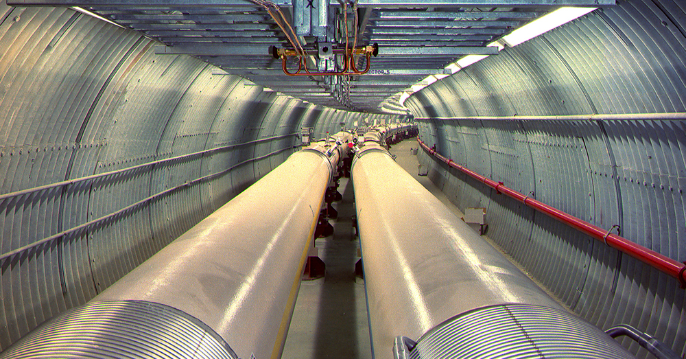
It is impossible to envisage high-energy physics without its foundation of microprocessor technology, software and distributed computing. Almost as soon as CERN was founded the first contract to provide a computer was signed, but it took manufacturer Ferranti more than two years to deliver “Mercury”, our first valve-based behemoth, in 1958. So early did this machine arrive that the venerable FORTRAN language had yet to be invented! A team of about 10 people was required for operations and the I/O system was already a bottleneck. It was not long before faster and more capable machines were available at the lab. By 1963, an IBM 7090 based on transistor technology was available with a FORTRAN compiler and tape storage. This machine could analyse 300,000 frames of spark-chamber data – a big early success. By the 1970s, computers were important enough that CERN hosted its first Computing and Data Handling School. It was clear that computers were here to stay.
By the time of the LEP era in the late 1980s, CERN hosted multiple large mainframes. Workstations, to be used by individuals or small teams, had become feasible. DEC VAX systems were a big step forward in power, reliability and usability and their operating system, VMS, is still talked of warmly by older colleagues in the field. Even more economical machines, personal computers (PCs), were also reaching a threshold of having enough computing power to be useful to physicists. Moore’s law, which predicted the doubling of transistor densities every two years, was well established and PCs were riding this technological wave. More transistors meant more capable computers, and every time transistors got smaller, clock speeds could be ramped up. It was a golden age where more advanced machines, running ever faster, gave us an exponential increase in computing power.
Key also to the computing revolution, alongside the hardware, was the growth of open-source software. The GNU project had produced many utilities that could be used by hackers and coders on which to base their own software. With the start of the Linux project to provide a kernel, humble PCs became increasingly capable machines for scientific computing. Around the same time, Tim Berners-Lee’s proposal for the World Wide Web, which began as a tool for connecting information for CERN scientists, started to take off. CERN realised the value in releasing the web as an open standard and in doing so enabled a success that today connects almost the entire planet.
LHC computing
This interconnected world was one of the cornerstones of the computing that was envisaged for the Large Hadron Collider (LHC). Mainframes were not enough, nor were local clusters. What the LHC needed was a worldwide system of interconnected computing systems: the Worldwide LHC Computing Grid (WLCG). Not only would information need to be transferred, but huge amounts of data and millions of computer jobs would need to be moved and executed, all with a reliability that would support the LHC’s physics programme. A large investment in brand new grid technologies was undertaken, and software engineers and physicists in the experiments had to develop, deploy and operate a new grid system utterly unlike anything that had gone before. Despite rapid progress in computing power, storage space and networking, it was extremely hard to make a reliable, working distributed system for particle physics out of these pieces. Yet we achieved this incredible task. During the past decade, thousands of physics results from the four LHC experiments, including the Higgs-boson discovery, were enabled by the billions of jobs executed and the petabytes of data shipped around the world.
The software that was developed to support the LHC is equally impressive. The community had made a wholesale migration from the LEP FORTRAN era to C++ and millions of lines of code were developed. Huge software efforts in every experiment produced frameworks that managed data taking and reconstruction of raw events to analysis data. In simulation, the Geant4 toolkit enabled the experiments to begin data-taking at the LHC with a fantastic level of understanding of the extraordinarily complex detectors, enabling commissioning to take place at a remarkable rate. The common ROOT foundational libraries and analysis environment allowed physicists to process the billions of events that the LHC supplied and extract the physics from them successfully at previously unheard of scales.
Changes in the wider world
While physicists were busy preparing for the LHC, the web became a pervasive part of people’s lives. Internet superpowers like Google, Amazon and Facebook grew up as the LHC was being readied and this changed the position of particle physics in the computing landscape. Where particle physics had once been a leading player in software and hardware, enjoying good terms and some generous discounts, we found ourselves increasingly dwarfed by these other players. Our data volumes, while the biggest in science, didn’t look so large next to Google; the processing power we needed, more than we had ever used before, was small beside Amazon; and our data centres, though growing, were easily outstripped by Facebook.
Technology, too, started to shift. Since around 2005, Moore’s law, while still largely holding, has no longer been accompanied by increases in CPU clock speeds. Programs that ran in a serial mode on a single CPU core therefore started to become constrained in their performance. Instead, performance gains would come from concurrent execution on multiple threads or from using vectorised maths, rather than from faster cores. Experiments adapted by executing more tasks in parallel – from simply running more jobs at the same time to adopting multi-process and multi-threaded processing models. This post hoc parallelism was often extremely difficult because the code and frameworks written for the LHC had assumed a serial execution model.
The barriers being discovered for CPUs also caused hardware engineers to rethink how to exploit CMOS technology for processors. The past decade has witnessed the rise of the graphics processing unit (GPU) as an alternative way to exploit transistors on silicon. GPUs run with a different execution model: much more of the silicon is devoted to floating-point calculations, and there are many more processing cores, but each core is smaller and less powerful than a CPU. To utilise such devices effectively, algorithms often have to be entirely rethought and data layouts have to be redesigned. Much of the convenient, but slow, abstraction power of C++ has to be given up in favour of more explicit code and simpler layouts. However, this rapid evolution poses other problems for the code long term. There is no single way to programme a GPU and vendors’ toolkits are usually quite specific to their hardware.
It is both a challenge and also an opportunity to work with new scientific partners in the era of exascale science
All of this would be less important were it the case that the LHC experiments were standing still, but nothing could be further from the truth. For Run 3 of the LHC, scheduled to start in 2021, the ALICE and LHCb collaborations are installing new detectors and preparing to take massively more data than they did up to now. Hardware triggers are being dropped in favour of full software processing systems and continuous data processing. The high-luminosity upgrade of the LHC for Run 4, from 2026, will be accompanied by new detector systems for ATLAS and CMS, much higher trigger rates and greatly increased event complexity. All of this physics needs to be supported by a radical evolution of software and computing systems, and in a more challenging sociological and technological environment. The LHC will also not be the only scientific big player in the future. Facilities such as DUNE, FAIR, SKA and LSST will come online and have to handle as much, if not more, data than at CERN and in the WLCG. That is both a challenge but also an opportunity to work with new scientific partners in the era of exascale science.
There is one solution that we know will not work: simply scaling up the money spent on software and computing. We will need to live with flat budgets, so if the event rate of an experiment increases by a factor of 10 then we have a budget per event that just shrank by the same amount! Recognising this, the HEP Software Foundation (HSF) was invited by the WLCG in 2016 to produce a roadmap for how to evolve software and computing in the 2020s – resulting in a community white paper supported by hundreds of experts in many institutions worldwide (CERN Courier April 2018 p38). In parallel, CERN open lab – a public–private partnership through which CERN collaborates with leading ICT companies and other research organisations – published a white paper setting out specific challenges that are ripe for tackling through collaborative R&D projects with leading commercial partners.
Facing the data onslaught
Since the white paper was published, the HSF and the LHC-experiment collaborations have worked hard to tackle the challenges it lays out. Understanding how event generators can be best configured to get good physics at minimum cost is a major focus, while efforts to get simulation speed-ups from classical fast techniques, as well as new machine-learning approaches, have intensified. Reconstruction algorithms have been reworked to take advantage of GPUs and accelerators, and are being seriously considered for Run 3 by CMS and LHCb (as ALICE makes even more use of GPUs since their successful deployment in Run 2). In the analysis domain, the core of ROOT is being reworked to be faster and also easier for analysts to work with. Much inspiration is taken from the Python ecosystem, using Jupyter notebooks and services like SWAN.
These developments are firmly rooted in the new distributed models of software development based on GitHub or GitLab and with worldwide development communities, hackathons and social coding. Open source is also vital, and all of the LHC experiments have now opened up their software. In the computing domain there is intense R&D into improving data management and access, and the ATLAS-developed Rucio data management system is being adopted by a wide range of other HEP experiments and many astronomy communities. Many of these developments got a shot in the arm from the IRIS–HEP project in the US; other European initiatives, such as IRIS in the UK and the IDT-UM German project are helping, though much more remains to be done.
All this sets us on a good path for the future, but still, the problems remain significant, the implementation of solutions is difficult and the level of uncertainty is high. Looking back to the first computers at CERN and then imagining the same stretch of time into the future, predictions are next to impossible. Disruptive technology, like quantum computing, might even entirely revolutionise the field. However, if there is one thing that we can be sure of, it’s that the next decades of software and computing at CERN will very likely be as interesting and surprising as the ones already passed.
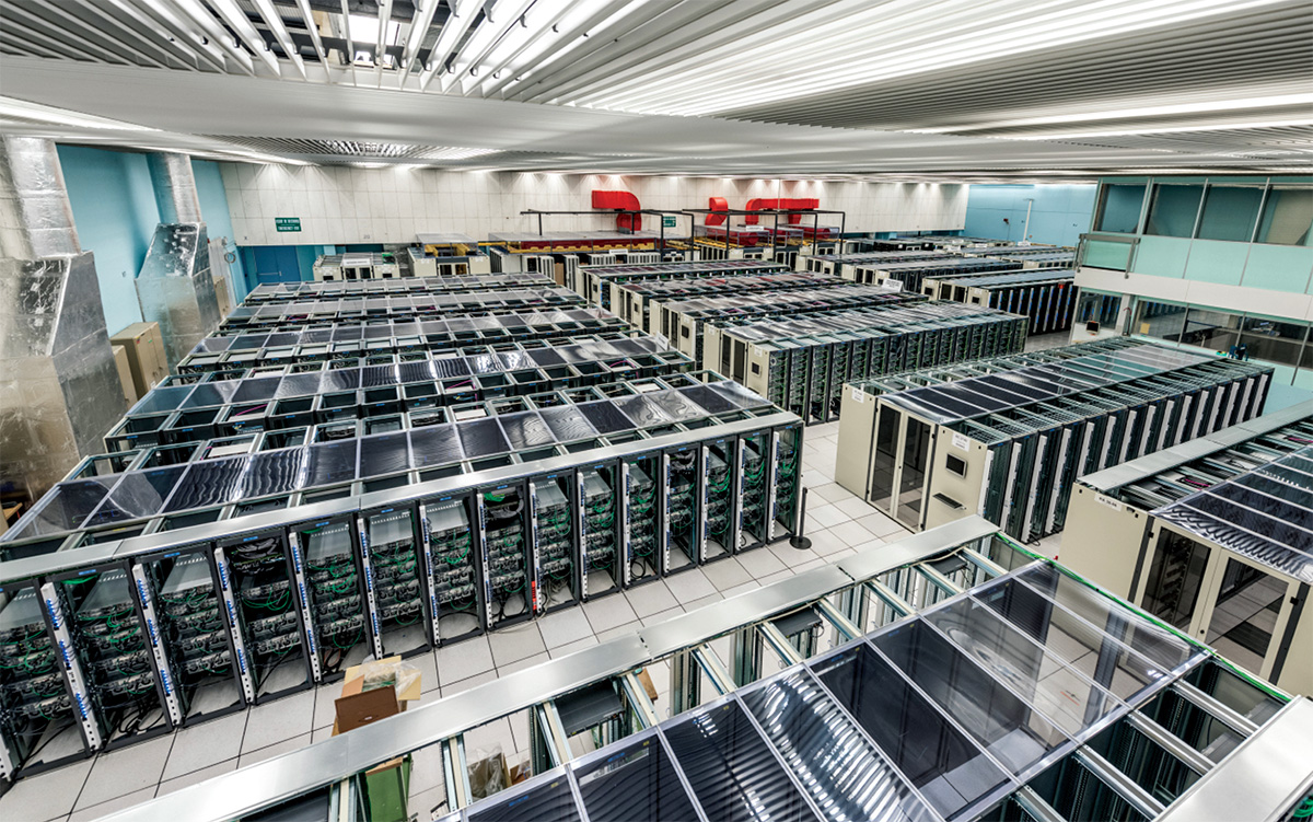
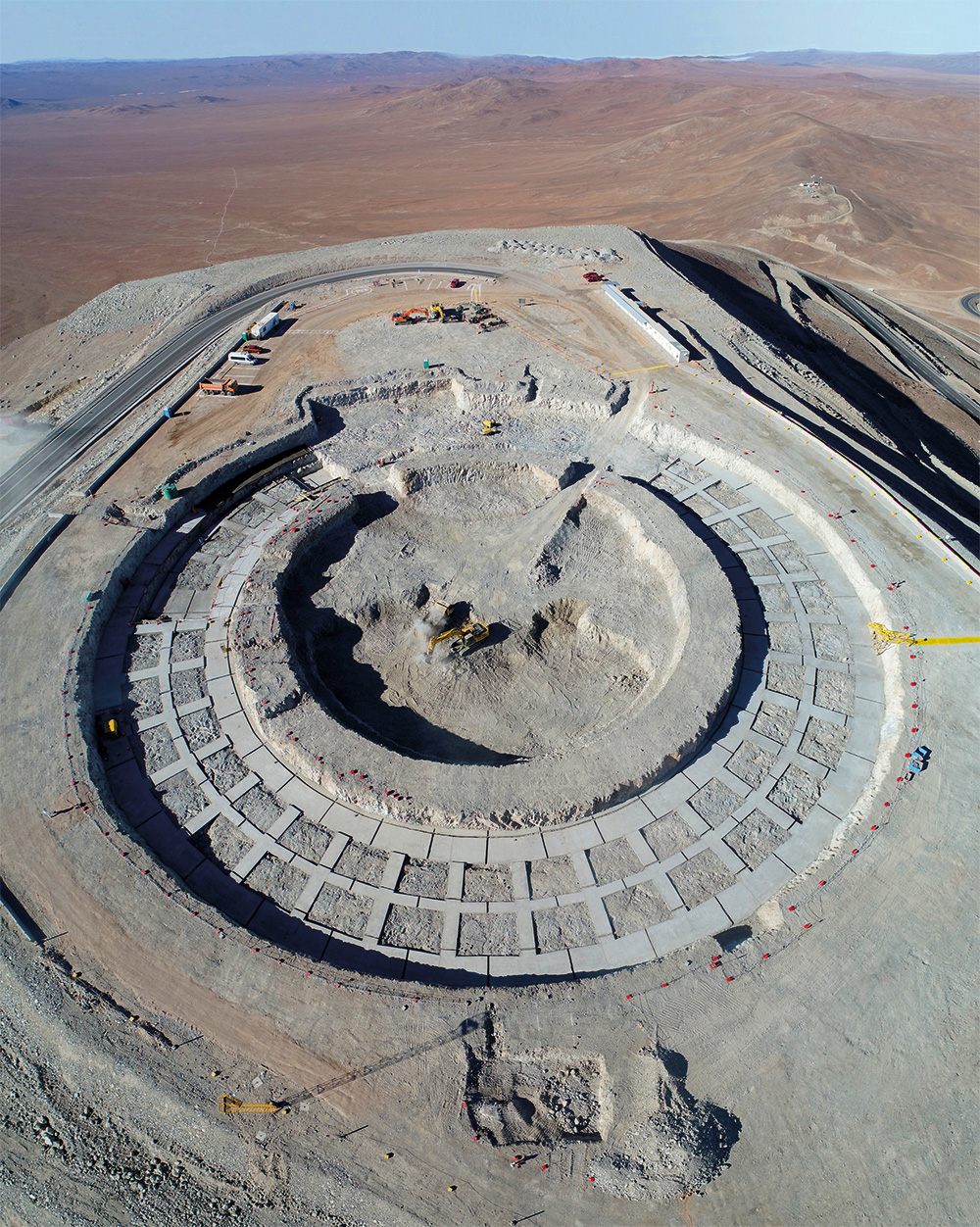
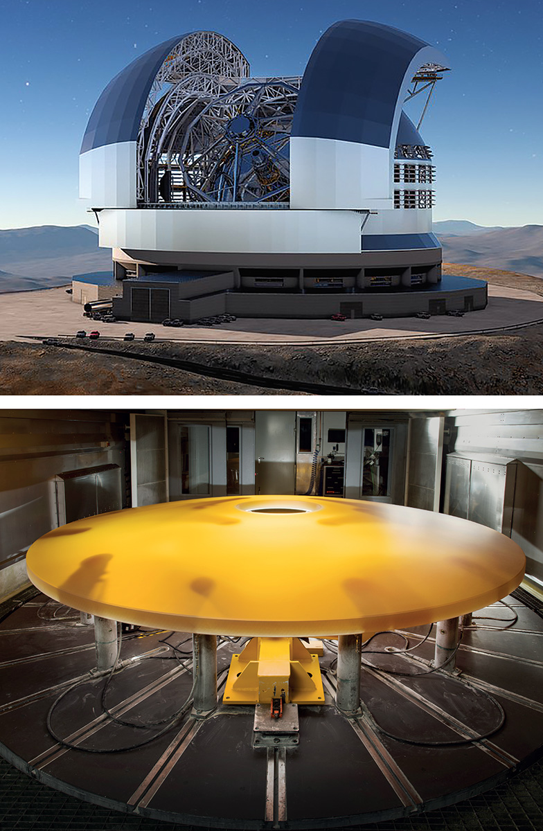
The 3 km-high summit of Cerro Armazones, located in the Atacama desert of Northern Chile, is a construction site for one of most ambitious projects ever mounted by astronomers: the Extremely Large Telescope (ELT). Scheduled for first light in 2025, the ELT is centred around a 39 m-diameter main mirror that will gather 250 times more light than the Hubble Space Telescope and use advanced corrective optics to obtain exceptional image quality. It is the latest major facility of the European Southern Observatory (ESO), which has been surveying the southern skies for almost 60 years.
The science goals of the ELT are vast and diverse. Its sheer size will enable the observation of distant objects that are currently beyond reach, allowing astronomers to better understand the formation of the first stars, galaxies and even black holes. The sharpness of its images will also enable a deeper study of extrasolar planets, possibly even the characterisation of their atmospheres. “One new direction may become possible through very high precision spectroscopy – direct detection of the expansion rate of the universe, which would be an amazing feat,” explains Pat Roche of the University of Oxford and former president of the ESO council. “But almost certainly the most exciting results will be from unexpected discoveries.”
Technical challenges
Approved in 2006, civil engineering for the ELT began in 2014. Construction of the 74 m-high, 86 m-diameter dome and the 3400-tonne main structure began in 2019. In January 2018 the first segments of the main mirror were successfully cast, marking the first step of a challenging five-mirror system that goes beyond the traditional two-mirror “Gregorian” design. The introduction of a third powered mirror delivers a focal plane that remains un-aberrated at all field locations, while a fourth and a fifth mirror correct distortions in real-time due to the Earth’s atmosphere or other external factors. This novel arrangement, combined with the sheer size of the ELT, makes almost every aspect of the design particularly challenging.
The main mirror is itself a monumental enterprise; it consists of 798 hexagonal segments, each measuring approximately 1.4 m across and 50 mm thick. To keep the surface unchanged by external factors such as temperature or wind, each segment has edge sensors measuring its location within a few nanometres – the most accurate ever used in a telescope. The construction and polishing of the segments, as well as the edge sensors, is a demanding task and only possible thanks to the collaboration with industry; at least seven private companies are working on the main mirror alone. The size of the mirror was originally 42 m, but it was later reduced to 39 m, mainly for costs reasons, but still allowing the ELT to fulfill its main scientific goals. “The ELT is ESO’s largest project and we have to ensure that it can be constructed and operated within the available budget,” says Roche. “A great deal of careful planning and design, most of it with input from industry, was undertaken to understand the costs and the cost drivers, and the choice of primary mirror diameter emerged from these analyses.”
The task is not much easier for the other mirrors. The secondary mirror, measuring 4 m across, is highly convex and will be the largest secondary mirror ever employed on a telescope and the largest convex mirror ever produced. The ELT’s tertiary mirror also has a curved surface, contrary to more traditional designs. The fourth mirror will be the largest adaptive mirror ever made, supported by more than 5000 actuators that will deform and adjust its shape in real-time to achieve a factor-500 improvement in resolution.
Currently 28 companies are actively collaborating on different parts of the ELT design; most of these companies are European, but also include contracts with the Chilean companies ICAFAL, for the road and platform construction, and Abengoa for the ELT technical facility. Among the European contracts, the construction of the telescope dome and main structure by the Italian ACe consortium of Astraldi and Cimolai is the largest in ESO’s history. The total cost estimate for the baseline design of the ELT is €1.174 billion, while the running cost is estimated to be around €50 million per year. Since the approval of the ELT, ESO has increased its number of member states from 14 to 16, with Poland and Ireland incorporating in 2015 and 2018, respectively. Chile is a host state and Australia a strategic partner.
European Southern Observatory’s particle-physics roots
The ELT’s success lies in ESO’s vast experience in the construction of innovative telescopes. The idea for ESO, a 16-nation intergovernmental organisation for research in ground-based astronomy, was conceived in 1954 with the aim of creating a European observatory dedicated to observations of the southern sky. At the time, the largest such facilities had an aperture of about 2 m; more than 50 years later, ESO is responsible for a variety of observatories, including its first telescope at La Silla, not far from Cerro Armazones (home of the ELT).
Like CERN, ESO was born in the aftermath of the war to allow European countries to develop scientific projects that nations were unable to do on their own. The similarities are by no means a mere coincidence. From the beginning, CERN served as a model regarding important administrative aspects of the organisation, such as the council delegate structure, the finance base or personnel regulations. A stronger collaboration ensued in 1969, when ESO approached CERN to assist with the powerful and sophisticated instrumentation of its 3.6 m telescope and other challenges ESO was facing, both administrative and technological. This collaboration saw ESO facilities established at CERN: the Telescope Project Division and, a few years later, ESO’s Sky Atlas Laboratory. A similar collaboration has since been organised for EMBL and, more recently for a new hadron-therapy facility in Southeast Europe.
Unprecedented view
A telescope of this scale has never been attempted before in astronomy. Not only must the ELT be constructed and operated within the available budget, but it should not impact the operation of ESO’s current flagship facilities (such as the VLT, the VLT interferometer and the ALMA observatory).
The amount of data produced by the ELT is estimated to be around 1-2 TB per night, including scientific observations plus calibration observations. The data will be analysed automatically, and users have the option to download the processed data or, if needed, download the original data and process it in their own research centres. To secure observation time with the facility, ESO makes a call for proposals once or twice a year, at which researchers propose desired observations according to their own fields. “A committee of astronomers then evaluates the proposals and ranks them according to their relevance and potential scientific impact, the highest ranked ones are then chosen to be followed,” explains project scientist Miguel Pereira of the University of Oxford.
Currently, 28 companies are actively collaborating on different parts of the ELT design, mostly from Europe
In addition to its astronomical goals, the ELT will contribute to the growing confluence of cosmology and fundamental physics. Specifically, it will help elucidate the nature of dark energy by identifying distant type 1a supernovae, which serve as excellent markers of the universe’s expansion history. The ELT will also measure the change in redshift with time of distant objects – a feat that is beyond the capabilities of current telescopes – to indicate the rate of expansion. Possible variations over time of fundamental physics constants, such as the fine-structure constant and the strong coupling constant, will also be targeted. Such measurements are very challenging because the strength of the constraint on the variability depends critically on the accuracy of the wavelength calibration. The ELT’s ultra-stable high-resolution spectrograph aims to remove the systematic uncertainty currently present in the wavelength calibration measurements, offering the possibility to make an unambiguous detection of such variations.
The ELT construction is on schedule for completion, and first light is expected in 2025. “In the end, projects succeed because of the people who design, build and support them,” Roche says, attributing the success of the ELT to rigorous attention to design and analysis across all aspects of the project. The road ahead is still challenging and full of obstacles, but, as the former director of the Paris observatory André Danjon wrote to his counterpart at the Leiden Observatory, Jan Oort, in 1962: “L’astronomie est bien l’ecole de la patience.” No doubt the ELT will pay extraordinary scientific rewards.
Concise and accessible, Calorimetry for Collider Physics is a reference book worthy of the name. Well known experts Michele Livan and Richard Wigmans have written an up-to-date introduction to both the fundamental physics and the technical parameters that determine the performance of calorimeters. Students and senior experts alike will be inspired to deepen their study of the characteristics of these instruments – instruments that have become crucial to most contemporary experiments in particle physics.
Following a light and attractive introductory chapter, the reader is invited to refresh his or her knowledge of the interactions of particles with matter. Key topics such as shower development, containment and profile, linearity and energy resolution are discussed for both electromagnetic and hadronic components. The authors provide illustrations with test-beam results and detailed Monte Carlo simulations. Practical and numerical examples help the reader to understand even counterintuitive effects, stimulating critical thinking in detector designers, and helping the reader develop a feeling for the importance of the various parameters that affect calorimetry.
The authors do not shy away from criticising calorimetric approaches
An important part of the book is devoted to hadron calorimetry. The authors have made a remarkably strong impact in understanding the fundamental problems with large set-ups in test beams, for example the famous lead-fibre sampling spaghetti calorimeter SPACAL. Among other issues, they correct “myths” as to which processes really cause compensation, and discuss quantities that correlate to the invisible energy fraction from hadrons involved in the shower process, for example, to measure the electromagnetic shower fraction event-by-event. The topical development of the dual-readout calorimeter concept follows logically from there – a very promising future direction for this central detector component, as the book discusses in considerable detail. This technology would avoid the question of longitudinal segmentation, which has a particular impact on linearity and calibration.
Livan and Wigmans’ book also gives a valuable historical overview of the field, and corrects several erroneous interpretations of past experimental results. The authors do not shy away from criticising calorimetric approaches in former, present and planned experiments, making the book “juicy” reading for experts. The reader will not be surprised that the authors are, for example, rather critical about highly segmented calorimeters aiming at particle flow approaches.
There is only limited discussion about other aspects of calorimetry, such as triggering, measuring jets and integrating calorimeters into an overall detector concept, which may impose many constraints on their mechanical construction. These aspects were obviously considered beyond the scope of the book, and indeed one cannot pack everything into a single compact textbook, though the authors do include a very handy appendix with tables of parameters relevant to calorimetry.
By addressing the fundamentals of calorimetry, Livan and Wigmans have provided an outstanding reference book. I recommend it highly to everybody interested in basic detector aspects of experimental physics. It is pleasant and stimulating to read, and if in addition it triggers critical thinking, so much the better!
Accelerator physicists in the US have proposed an alternative approach to the design of the proposed Future Circular electron-positron Collider (FCC-ee), generating lively discussions in the community on the eve of the update of the European strategy for particle physics. A 360-page long conceptual design report for the 100 km FCC-ee, a possible successor to the high-luminosity LHC at CERN, was published in January following a five-year study by the international FCC collaboration. A key consideration of the baseline design was to minimise energy consumption — a challenge addressed by the novel US proposal based on technology recently explored for future electron-ion and electron-proton colliders.
The modified acceleration scheme, laid out in a preprint published recently by Vladimir Litvinenko (Stony Brook) and Thomas Roser and Maria Chamizo-Llatas (Brookhaven National Laboratory), uses Energy Recovery Linacs (ERLs) to purportedly reduce synchrotron radiation by a factor of ten compared to the FCC-ee baseline design. “In addition to the potential power saving, the ERL version of the FCC-ee could extend the centre-of-mass energy reach up to 600 GeV while providing very high luminosities,” says Chamizo-Llatas. The maximum energy discussed in the conceptual design report for the FCC-ee baseline is 365 GeV, as required for top-antitop production.
First proposed by Maury Tigner in 1965, ERLs recoup the kinetic energy of particle bunches by manipulating their arrival time in the radio-frequency (RF) cavities. Previously accelerated bunches encounter a decelerating electric field, and the regained energy, stored once again in the cavity’s field, may be recycled to accelerate subsequent bunches. Though an old idea, ERLs are only now becoming feasible due to the high quality of modern superconducting RF cavities.
In June the Cornell–Brookhaven ERL Test Accelerator (CBETA) facility, which was envisaged as an ERL demonstrator for the Electron-Ion Collider (EIC) proposed in the US, achieved full energy recovery for a single pass. Prior to this, the concept was demonstrated at Jefferson Laboratory in the US and at Daresbury Laboratory in the UK. Further R&D with cavity technology compatible with FCC-ee proposal is planned for the Powerful Energy-Recovery Linac for Experiments (PERLE) project at Orsay, which was conceived as a test facility for electron-proton colliders.
The basic feasibility of the proposed concept must still be demonstrated
Frank Zimmermann
The US trio’s alternative FCC-ee proposal, which was inspired by past design work for the EIC, maintains high beam quality by decelerating the beams after every collision at one of the interaction points, and “cooling” them in dedicated rings. The use of ERLs allows the beams to be decelerated, cooled and re-accelerated with minimal energy expended, potentially yielding much lower emittances than found in conventional circular machines. “The electric power consumption of a future FCC-ee will be a limiting factor for luminosity and centre-of-mass energy,” says Roser. “During our design studies for the EIC we realised that using an ERL for the electrons could produce significantly more luminosity for a given electron beam current,” he explains, though the team admits that their concept would require extensive studies similar to what the FCC-ee design team did for the storage-ring design.
The BNL proposal is certainly tantalising, agrees FCC deputy study leader Frank Zimmermann of CERN. “Presently, Energy Recovery Linacs are a topic of great worldwide interest, with efforts ongoing, for example, at Cornell, Jefferson Lab, KEK, Mainz, and Orsay,” he says. “However, the basic feasibility of the proposed concept must still be demonstrated and the potentially high investment cost understood, before this approach could be considered as a highest-energy option for a future circular lepton collider.”
Teeming with radiation and data, the heart of a hadron collider is an inhospitable environment in which to make a tricky decision. Nevertheless, the LHC experiment detectors have only microseconds after each proton–proton collision to make their most critical analysis call: whether to read out the detector or reject the event forever. As a result of limitations in read-out bandwidth, only 0.002% of the terabits per second of data generated by the detectors can be saved for use in physics analyses. Boosts in energy and luminosity – and the accompanying surge in the complexity of the data from the high-luminosity LHC upgrade – mean that the technical challenge is growing rapidly. New techniques are therefore needed to ensure that decisions are made with speed, precision and flexibility so that the subsequent physics measurements are as sharp as possible.
The front-end and read-out systems of most collider detectors include many application-specific integrated circuits (ASICs). These custom-designed chips digitise signals at the interface between the detector and the outside world. The algorithms are baked into silicon at the foundries of some of the biggest companies in the world, with limited prospects for changing their functionality in the light of changing conditions or detector performance. Minor design changes require substantial time and money to fix, and the replacement chip must be fabricated from scratch. In the LHC era, the tricky trigger electronics are therefore not implemented with ASICs, as before, but with field-programmable gate arrays (FPGAs). Previously used to prototype the ASICs, FPGAs may be re-programmed “in the field”, without a trip to the foundry. Now also prevalent in high-performance computing, with leading tech companies using them to accelerate critical processing in their data centres, FPGAs offer the benefits of task-specific customisation of the computing architecture without having to set the chip’s functionality in stone – or in this case silicon.
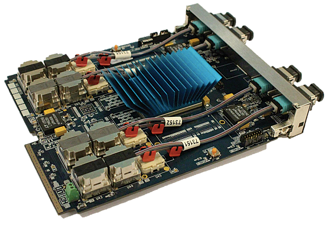
FPGAs can compete with other high-performance computing chips due to their massive capability for parallel processing and relatively low power consumption per operation. The devices contain many millions of programmable logic gates that can be configured and connected together to solve specific problems. Because of the vast numbers of tiny processing units, FPGAs can be programmed to work on many different parts of a task simultaneously, thereby achieving massive throughput and low latency – ideal for increasingly popular machine-learning applications. FPGAs can also support high bandwidth inputs and outputs of up to about 100 dedicated high-speed serial links, making them ideal workhorses to process the deluge of data that streams out of particle detectors (see CERN Courier September 2016 p21).
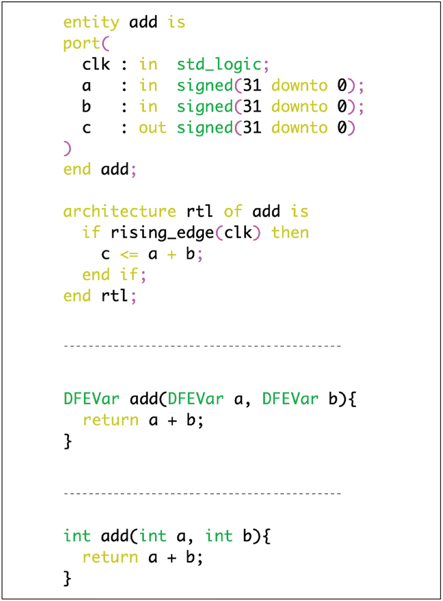
The difficulty is that programming FPGAs is traditionally the preserve of engineers coding low-level languages such as VHDL and Verilog, where even simple tasks can be tricky. For example, a function to sum two numbers together requires several lines of code in VHDL, with the designer even required to define when the operations happen relative to the processor clock (figure 1). Outsourcing the coding is impractical, given the imminent need to implement elaborate algorithms featuring machine learning in the trigger to quickly analyse data from high-granularity detectors in high-luminosity environments. During the past five years, however, tools have matured, allowing FPGAs to be programmed in variants of high-level languages such as C++ and Java, and bringing FPGA coding within the reach of physicists themselves.
But can high-level tools produce FPGA code with low-enough latency for trigger applications? And can their resource usage compete with professionally developed low-level code? During the past couple of years CMS physicists have trialled the use of a Java-based language, MaxJ, and tools from Maxeler Technologies, a leading company in accelerated computing and data-flow engines, who were partners in the studies. More recently the collaboration has also gained experience with the C++-based Vivado high-level synthesis (HLS) tool of the FPGA manufacturer Xilinx. The work has demonstrated the potential for ground-breaking new tools to be used in future triggers, without significantly increasing resource usage and latency.
Track and field-programmable
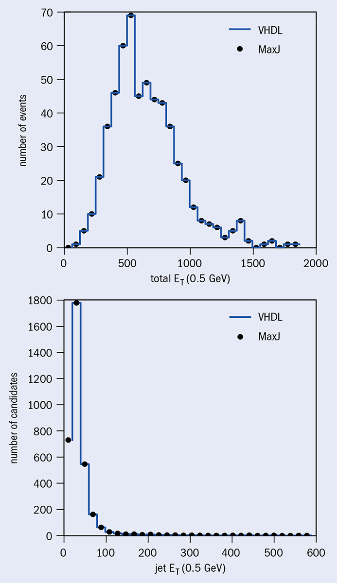
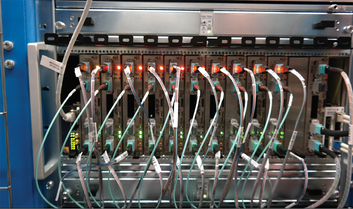
Tasked with finding hadronic jets and calculating missing transverse energy in a few microseconds, the trigger of the CMS calorimeter handles an information throughput of 6.5 terabits per second. Data are read out from the detector into the trigger-system FPGAs in the counting room in a cavern adjacent to CMS. The official FPGA code was implemented in VHDL over several months each of development, debugging and testing. To investigate whether high-level FPGA programming can be practical, the same algorithms were implemented in MaxJ by an inexperienced doctoral student (figure 2), with the low-level clocking and management of high-speed serial links still undertaken by the professionally developed code. The high-level code had comparable latency and resource usage with one exception: the hand-crafted VHDL was superior when it came to quickly sorting objects by their transverse momentum. With this caveat, the study suggests that using high-level development tools can dramatically lower the bar for developing FPGA firmware, to the extent that students and physicists can contribute to large parts of the development of labyrinthine electronics systems.
Kalman filtering is an example of an algorithm that is conventionally used for offline track reconstruction on CPUs, away from the low-latency restrictions of the trigger. The mathematical aspects of the algorithm are difficult to implement in a low-level language, for example requiring trajectory fits to be iteratively optimised using sequential matrix algebra calculations. But the advantages of a high-level language could conceivably make Kalman filtering tractable in the trigger. To test this, the algorithm was implemented for the phase-II upgrade of the CMS tracker in MaxJ. The scheduler of Maxeler’s tool, MaxCompiler, automatically pipelines the operations to achieve the best throughput, keeping the flow of data synchronised. This saves a significant amount of effort in the development of a complicated new algorithm compared to a low-level language, where this must be done by hand. Additionally, MaxCompiler’s support for fixed-point arithmetic allows the developer to make full use of the capability of FPGAs to use custom data types. Tailoring the data representation to the problem at hand results in faster, more lightweight processing, which would be prohibitively labour-intensive in a low-level language. The result of the study was hundreds of simultaneous track fits in a single FPGA in just over a microsecond.
Ghost in the machine
Deep neural networks, which have become increasingly prevalent in offline analysis and event reconstruction thanks to their ability to exploit tangled relationships in data, are another obvious candidate for processing data more efficiently. To find out if such algorithms could be implemented in FPGAs, and executed within the tight latency constraints of the trigger, an example application was developed to identify fake tracks – the inevitable byproducts of overlapping particle trajectories – in the output of the MaxJ Kalman filter described above. Machine learning has the potential to distinguish such bogus tracks better than simple selection cuts, and a boosted decision tree (BDT) proved effective here, with the decision step, which employs many small and independent decision trees, implemented with MaxCompiler. A latency of a few hundredths of a microsecond – much shorter than the iterative Kalman filter as BDTs are inherently very parallelisable – was achieved using only a small percentage of the silicon area of the FPGA, so leaving room for other algorithms. Another tool capable of executing machine-learning models in tens of nanoseconds is the “hls4ml” FPGA inference engine for deep neural networks, built on the Vivado HLS compiler of Xilinx. With the use of such tools, non-FPGA experts can trade-off latency and resource usage – two critical metrics of performance, which would require significant extra effort to balance in collaboration with engineers writing low-level code.
Though requiring a little extra learning and some knowledge of the underlying technology, it is now possible for ordinary physicists to programme FPGAs in high-level languages, such as Maxeler’s MaxJ and Xilinx’s Vivado HLS. Development time can be cut significantly, while maintaining latency and resource usage at a similar level to hand-crafted FPGA code, with the fast development of mathematically intricate algorithms an especially promising use case. Opening up FPGA programming to physicists will allow offline approaches such as machine learning to be transferred to real-time detector electronics.
Novel approaches will be critical for all aspects of computing at the high-luminosity LHC. New levels of complexity and throughput will exceed the capability of CPUs alone, and require the extensive use of heterogenous accelerators such as FPGAs, graphics processing units (GPUs) and perhaps even tensor processing units (TPUs) in offline computing. Recent developments in FPGA interfaces are therefore most welcome as they will allow particle physicists to execute complex algorithms in the trigger, and make the critical initial selection more effective than ever before.
Accelerator experts from around the world met from 30 June – 5 July in Dresden’s historic city centre for six days of intense discussions on superconducting radio-frequency (SRF) science and technology. The Helmholtz-Zentrum Dresden-Rossendorf (HZDR) hosted the 19th conference in the biannual series, which demonstrated that SRF has matured to become the enabling technology for many applications. New SRF-based large-scale facilities throughout the world include the European XFEL in Germany, LCLS-II and FRIB in the US, ESS in Sweden, RAON in Korea, and SHINE in China.
The conference opened on Germany’s hottest day of the year with a “young scientists” session comprising 40 posters. The following week featured a programme packed with 67 invited oral presentations, more than 300 posters and an industrial exhibition. Keynote lecturer Thomas Tschentscher (European XFEL) discussed applications of high-repetition-rate SRF-based X-ray sources, while Andreas Maier (University of Hamburg) reviewed rapidly advancing laser-plasma accelerators, emphasising their complementarity with SRF-based systems.
Much excitement in the community was generated by new, fundamental insights into power dissipation in RF superconductors. A better understanding of the role of magnetic flux trapping and impurities for RF losses has pushed state-of-the-art niobium to near its theoretical limit. However, recent advances with Nb3Sn (CERN Courier July/August 2019 p9) have demonstrated performance levels commensurate with established niobium systems, but at a much higher operating temperature (≥ 4.2 K rather than ≤ 2 K). Such performance was unthinkable just a few years ago. Coupled with technological developments for tuners, digital control systems and cavity processing, turn-key high-field and continuous-wave operation at 4.2 K and above appears within reach. The potential benefit for both large-scale facilities as well as compact SRF-based accelerators in terms of cost and complexity is enormous.
The SRF conference traditionally plays an important role in attracting new, young researchers and engineers to the field, and provides them with a forum to present their results. In the three days leading up to the conference, HZDR hosted tutorials covering all aspects from superconductivity fundamentals to cryomodule design, which attracted 89 students and young scientists. During the conference, 18 young investigators were invited to give presentations. Bianca Giaccone (Fermilab) and Ryan Porter (Cornell University) received prizes for the best talks, alongside Guilherme Semione (DESY) for best poster.
The SRF conference rotates between Europe, Asia and the Americas. SRF 2021 will be hosted by Michigan State University/FRIB, while SRF 2023 moves on to Japan’s Riken Nishina Center.
Accelerators of unstable or non-naturally occurring particles, such as the proton–antiproton colliders with which the W, Z and top quark were discovered, famously rely on “beam-cooling” techniques, which reduce the beam’s phase-space volume in order to achieve sufficient interaction rates. Cooling techniques continue to improve, enhancing current and future experiments using low-energy antiprotons, heavy ions and molecular beams, and enabling future muon colliders. The community of scientists and engineers developing and applying beam cooling has been meeting to exchange ideas for more than 20 years at the COOL workshops.
It was gratifying to see the proliferation and progress of beam-cooling technologies at the 12th biennial international workshop on beam cooling and related topics, held from 23–27 September at the Budker Institute of Nuclear Physics (BINP) in Novosibirsk , Russia. Electron-cooling R&D platforms were represented in profusion, including in the US (RHIC at Brookhaven and the planned EIC at Brookhaven and JLab), Germany (COSY at the Forschungszentrum Jülich, the CSR at MPI-K Heidelberg, and R&D at HIM Mainz), China (EICC and HIAF at IMP Lanzhou), CERN (the AD and ELENA), and Russia (NICA at JINR Dubna). Most of these are joint efforts with BINP, which continues to be the primary source for high-voltage, electron-gun and solenoid systems for such coolers. Also represented were stochastic cooling installations, tests of coherent electron cooling, and, at long last, results from the Muon Ionisation Cooling Experiment – notably, the first observation of muon ionisation cooling (first conceived at BINP almost 50 years ago), and a measurement of multiple scattering in a lithium-hydride energy absorber. Results with liquid hydrogen, and a wedge-shaped plastic absorber designed to demonstrate emittance exchange between the transverse and longitudinal planes, are expected soon.
It was unfortunate that no one from a US national laboratory was able to travel to Novosibirsk in person – apparently a casualty of anti-Russia sanctions
Another highlight of the workshop was the report from Brookhaven, “Cooling commissioning results of the first RF-based electron cooler LEReC,” which was delivered remotely by Alexei Fedotov. It was unfortunate that no one from a US national laboratory was able to travel to Novosibirsk in person – apparently a casualty of anti-Russia sanctions. Even at the height of the Cold War, US–USSR scientific contacts in particle and accelerator physics were successfully pursued. The argument that by cutting off such contacts one is shooting oneself in the foot seems quite plausible – after all, we go in order to learn.
The steady increase in the energy of colliders during the past 40 years was possible thanks to progress in superconducting materials and accelerator magnets. The highest particle energies have been reached by proton–proton colliders, where beams of high-rigidity travelling on a piecewise circular trajectory require magnetic fields largely in excess of those that can be produced using resistive electromagnets. Starting from the Tevatron in 1983, through HERA in 1991 (see Constructing HERA: rising to the challenge), RHIC in 2000 and finally the LHC in 2008 (see LHC insertions: the key to CERN’s new accelerator and Superconductivity and the LHC: the early days), all large-scale hadron colliders were built using superconducting magnets.
Large superconducting magnets for detectors are just as important to large high-energy physics experiments as beamline magnets are to particle accelerators. In fact, detector magnets are where superconductivity took its stronghold, right from the infancy of the technology in the 1960s, with major installations such as the large bubble-chamber solenoid at Argonne National Laboratory, followed by the giant BEBC solenoid at CERN, which held the record for the highest stored energy for many years. A long line of superconducting magnets has provided the field to the detectors of all large-scale high-energy physics colliders (see ALEPH coil hits the road and CMS: a super solenoid is ready for business), with the last and largest realisation being the LHC experiments, CMS and ATLAS.
All past accelerator and detector magnets have one thing in common: they were built using composite Nb-Ti/Cu wires and cables. Nb-Ti is a ductile alloy with a critical field of 14.5 T and critical temperature of 9.2 K, made from almost equal parts of the two constituents and discovered to be superconducting in 1962. Its performance, quality and cost have been optimised over more than half a century of research, development and large-scale industrial production. Indeed, it is unlikely that the performance of the LHC dipole magnets, operated so far at 7.7 T and expected to reach nominal conditions at 8.33 T, can be surpassed using the same superconducting material, or any foreseeable improvement of this alloy.
The HL-LHC springboard
And yet, approved projects and studies for future circular machines are all calling for the development of superconducting magnets that produce fields beyond those produced for the LHC. These include the High-Luminosity LHC (HL-LHC), which is currently taking place, and the Future Circular Collider design study (FCC), both at CERN, together with studies and programmes outside Europe, such as the Super proton–proton Collider in China (SppC) or the past studies of a Very Large Hadron Collider at Fermilab and the US–DOE Muon Accelerator Program. This requires that we turn to other superconducting materials and novel magnet technology.
To reach its main objective, to increase the levelled LHC luminosity at ATLAS and CMS by a factor of five and the integrated one by a factor of 10, HL-LHC requires very large-aperture quadrupoles, with field levels at the coil in the range of 12 T in the interaction regions. These quadrupoles, currently being produced, are the main fruit of the 10-year US-DOE LHC Accelerator ResearchProgram (US–LARP) – a joint venture between CERN, Brookhaven National Laboratory, Fermilab and Lawrence Berkeley National Laboratory. In addition, the increased beam intensity calls for collimators to be inserted in locations within the LHC “dispersion suppressor”, the portion of the accelerator where the regular magnet lattice is modified to ensure that off-momentum particles are centered in the interaction points. To gain the required space, standard arc dipoles will be substituted by dipoles of shorter length and higher field, approximately 11 T. As described earlier, such fields require the use of new materials. For HL-LHC, the material of choice is the inter-metallic compound of niobium and tin Nb3Sn, which was discovered in 1954. Nb3Sn has a critical field of 30 T and a critical temperature of 18 K, outperforming Nb-Ti by a factor two. Though discovered before Nb-Ti, and exhibiting better performance, Nb3Sn has not been used for accelerator magnets so far because in its final form it is brittle and cannot withstand large stress and strain without special precautions.
In fact, Nb3Sn was one of the candidate materials considered for the LHC in the late 1980s and mid 1990s. Already at that time it was demonstrated that accelerator magnets could be built with Nb3Sn, but it was also clear that the technology was complex, with a number of critical steps, and not ripe for large-scale production. A good 20 years of progress in basic material performance, cable development, magnet engineering and industrial process control was necessary to reach the present state, during which time the success of the production of Nb3Sn for ITER (see ITER’s massive magnets enter production) has given confidence in the credibility of this material for large-scale applications. As a result, magnet experts are now convinced that Nb3Sn technology is sufficiently mature to satisfy the challenging field levels required by HL-LHC.
The present manufacturing recipe for Nb3Sn accelerator magnets consists of winding the magnet coil with glass-fibre insulated cables made of multi-filamentary wires that contain Nb and Sn precursors in a Cu matrix. In this form the cables can be handled and plastically deformed without breakage. The coils then undergo heat treatment, typically at a temperature of around 600 to 700 °C, during which the precursor elements react chemically and form the desired Nb3Sn superconducting phase. At this stage, the reacted coil is extremely fragile and needs to be protected from any mechanical action. This is done by injecting a polymer, which fills the interstitial spaces among cables, and is subsequently cured to become a matrix of hardened plastic providing cohesion and support to the cables.
The above process, though conceptually simple, has a number of technical difficulties that call for top-of-the-line engineering and production control. To give some examples, the electrical insulation consisting of a few tenths of mm of glass-fibre needs to be able to withstand the high-temperature heat-treatment step, but also retain dielectric and mechanical properties at liquid helium temperatures 1000 degrees lower. The superconducting wire also changes its dimensions by a few percent, which is orders of magnitude larger than the dimensional accuracy requested for field quality and therefore must be predicted and accommodated for by appropriate magnet and tooling design. The finished coil, even if it is made solid by the polymer cast, still remains stress and strain sensitive. The level of stress that can be tolerated without breakage can be up to 150 MPa, to be compared to the electromagnetic stress of optimised magnets operating at 12 T that can reach levels in the range of 100 MPa. This does not leave much headroom for engineering margins and manufacturing tolerances. Finally, protecting high-field magnets from quench, with their large stored energy, requires that the protection system has a very fast reaction – three times faster than at the LHC – and excellent noise rejection to avoid false trips related to flux jumps in the large Nb3Sn filaments.
The CERN magnet group, in collaboration with the US-DOE laboratories participating in the LHC Accelerator Upgrade Project, is in the process of addressing these and other challenges, finding solutions suitable for a magnet production on the scale required for HL-LHC. A total of six 11 T dipoles (each about 6 m long) and 20 inner triplet quadrupoles (up to 7.5 m long) are in production. And yet, it is clear that we are not ready to extrapolate such production on a much larger scale, i.e. to the thousands of magnets required for a future hadron collider such as FCC-hh. This is exactly why HL-LHC is so critical to the development of high-field magnets for future accelerators: not only will it be the first demonstration of Nb3Sn magnets in operation, steering and colliding beams, but by building it on a scale that can be managed at the laboratory level we have a unique opportunity to identify all the areas of necessary development, and the open technology issues, to allow the next jump. Beyond its prime physics objective, HL-LHC is the springboard into the future of high-field accelerator magnets.
The climb to higher peak fields
For future circular colliders, the target dipole field has been set at 16 T for FCC-hh, allowing proton-proton collisions at an energy of 100 TeV, while the SppC aims at a 12 T dipole field as a first step, to be followed by a 20 T dipole. Are these field levels realistic? And based on which technology?
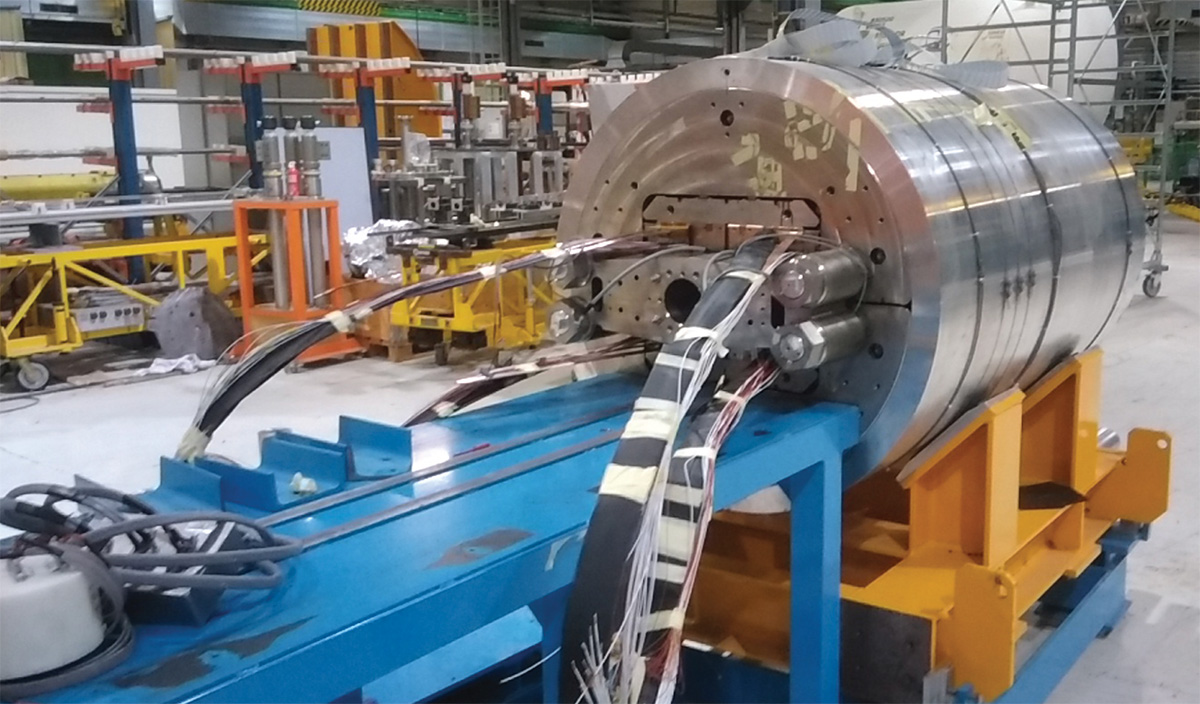
Looking at the dipole fields produced by Nb3Sn development magnets during the past 40 years (figure 1), fields up to 16 T have been achieved in R&D demonstrators, suggesting that the FCC target can be reached. In 2018 “FRESCA2” – a large-aperture dipole developed over the past decade through a collaboration between CERN and CEA-Saclay in the framework of the European Union project EuCARD – attained a record field of 14.6 T at 1.9 K (13.9 T at 4.5 K). Another very relevant recent result is the successful test at Fermilab of the high-field dipole MDPCT1, which reached a field of 14.1 T at 4.5 K earlier this year.
A field of 16 T seems to be the upper limit that can be reached with Nb3Sn. Indeed, though the conductor performance can still be improved, as demonstrated by recent results obtained at NHMFL, OSU and FNAL within the scope of the US-DOE Magnet Development Program, this is the point at which the material itself will run out of steam: as for any other superconductor, the critical current density drops as the field is increased, requiring an increasing amount of material to carry a given current. This effect becomes dramatic approaching a significant fraction of the critical field. Akin to Nb-Ti in the range of 8 T, a further field increase with Nb3Sn beyond 16 T would require an exceedingly large coil and an impractical amount of conductor. Reaching the ultimate performance of Nb3Sn, which will be situated between the present 12 T and the expected maximum of 16 T, still requires much work. The technology issues identified by the ongoing work on the HL-LHC magnets are exacerbated by the increase in field, electro-magnetic force and stored energy. Innovative industrial solutions will be needed, and the conductor itself brought to a level of maturity comparable to Nb-Ti in terms of performance, quality and cost. This work is the core of the ongoing FCC magnet development programme that CERN is pursuing in collaboration with laboratories, universities and industries worldwide.
As the limit of Nb3Sn comes into view, we see history repeating itself: the only way to push beyond it to higher fields will be to resort to new materials. Since Nb3Sn is technically the low-temperature superconductor (LTS) with the highest performance, this will require a transition to high-temperature superconductors (HTS).
Brave new world of HTS
High-temperature superconductors, discovered in 1986, are of great relevance in the quest for high fields. When operated at low temperature (the same liquid-helium range as LTS), they have exceedingly large critical fields in the range of 100 T and above. And yet, only recently the material and magnet engineering has reached the point where HTS materials can generate magnetic fields in excess of LTS ones. The first user applications coming to fruition are ultra-high-field NMR magnets, as recently delivered by Bruker Biospin, and the intense magnetic fields required by material science, for example the 32 T all-superconducting user facility built by the US National High Magnetic Field Laboratory.
As for their application in accelerator magnets, the potential of HTS to make a quantum leap is enormous. But it is also clear that the tough challenges that needed to be solved for Nb3Sn will escalate to a formidable level in HTS accelerator magnets. The magnetic force scales with the square of the field produced by the magnet, and for HTS the problem will no longer be whether the material can carry the super-currents, but rather how to manage stresses approaching structural material limits. Stored energy has the same square dependence on the field, and quench detection and protection in large HTS magnets are still a spectacular challenge. In fact, HTS magnet engineering will probably differ so much from the LTS paradigm that it is fair to say that we do not yet know whether we have identified all the issues that need to be solved. HTS is the most exciting class of material to work with; the new world for brave explorers. But it is still too early to count on practical applications, not least because the production cost for this rather complex class of ceramic materials is about two orders of magnitude higher than that of good old Nb-Ti.
It is quite logical to expect the near future to be based mainly on Nb3Sn. With the first demonstration to come imminently, in the LHC, we need to consolidate the technology and bring it to the maturity necessary on a large-scale production. This may likely take place in steps – exploring 12 T territory first, while seeking the solutions to the challenges of ultimate Nb3Sn performance towards 16 T – and could take as long as a decade.
Meanwhile, nurtured by novel ideas and innovative solutions, HTS could grow from the present state of a material of great potential to its first applications. The grand challenges posed by HTS will likely require a revolution rather than an evolution of magnet technology, and significant technology advancement leading to large-scale application in accelerators can only be imagined on the 25-year horizon.
Road to the future
There are two important messages to retain from this rather simplified perspective on high-field magnets for accelerators. Firstly, given the long lead times of this technology, and even in times of uncertainty, it is important to maintain a healthy and ambitious programme so that the next step in technology is at hand when critical decisions on the accelerators of the future are due. The second message is that with such long development cycles and very specific technology, it is not realistic to rely on the private sector to advance and sustain the specific demands of HEP. In fact, the business model of high-energy physics is very peculiar, involving long investment times followed by short production bursts, and not sustainable by present industry standards. So, without taking the place of industry, it is crucial to secure critical know-how and infrastructure within the field to meet development needs and ensure the long-term future of our accelerators, present and to come.
To provide the best experiences, we use technologies like cookies to store and/or access device information. Consenting to these technologies will allow us to process data such as browsing behavior or unique IDs on this site. Not consenting or withdrawing consent, may adversely affect certain features and functions.
Functional
Always active
The technical storage or access is strictly necessary for the legitimate purpose of enabling the use of a specific service explicitly requested by the subscriber or user, or for the sole purpose of carrying out the transmission of a communication over an electronic communications network.
Preferences
The technical storage or access is necessary for the legitimate purpose of storing preferences that are not requested by the subscriber or user.
Statistics
The technical storage or access that is used exclusively for statistical purposes.The technical storage or access that is used exclusively for anonymous statistical purposes. Without a subpoena, voluntary compliance on the part of your Internet Service Provider, or additional records from a third party, information stored or retrieved for this purpose alone cannot usually be used to identify you.
Marketing
The technical storage or access is required to create user profiles to send advertising, or to track the user on a website or across several websites for similar marketing purposes.