Surveying the geological, environmental and technical constraints of a post-LHC collider.
In 2012 the CERN management asked a question: what is the largest circular machine that could be feasibly constructed in the Geneva region from a civil-engineering perspective? Teams quickly embarked on an extensive investigation of the geological, environmental and technical constraints in pursuit of the world’s largest accelerator. Such a machine would be the next logical step in exploring the universe at ever smaller scales.
Since construction of the 27 km circumference Large Hadron Collider (LHC) was completed in 2005, CERN has been looking at the potential layouts for the tunnels that will house the next generation of particle accelerators. The Compact Linear Collider (CLIC) and the Future Circular Collider (FCC) are the two largest projects under consideration. With a circumference of 100 km, the FCC will require one of the world’s largest tunnels – almost twice as long as the recently completed 57 km Gotthard Base Tunnel in the Swiss Alps. Designing large infrastructure like the FCC tunnel requires the collection and interpretation of numerous data, which have to be balanced for the optimum level of risk, cost and project requirements.
The first and most important task in designing tunnels is to understand the needs and requirements of the users. For road or rail tunnels, this is relatively straightforward. For a cutting-edge scientific experiment, multi-disciplinary working groups are needed to identify the key criteria. The diameter of a new tunnel depends on what components would be inside – ventilation systems, magnets, lighting, transport corridors, etc – so they can fit in like a jigsaw.
Bespoke designs
Unlike other tunnelling projects, there are no standard rules or guidance for the design of particle-accelerator tunnels, meaning each design is, to a large extent, bespoke. One reason for this is the sensitivity of the equipment inside. Digging a 5.6 m-diameter hole disturbs rock that has been there for millennia, causing it to relax and to move. Modern tunnelling techniques can control these movements and get a tunnel to within a few centimetres of its intended design. For example, the two ends of the 27 km LEP ring came together with just 1 cm of error. It would be impossible to achieve the nanometre-level tolerances that the beamline requires, so the sensitive equipment installed in a completed accelerator tunnel must incorporate adjustable alignment systems into their designs.
The city of Geneva sits on a large plateau between the Jura and Prealps mountains. The bedrock of the plateau is a competent (resistant to deformation) sedimentary rock, called molasse, which formed when eroded material was deposited and consolidated in a basin as the Alps lifted up. On top of the molasse sits a softer soil, called the moraines, which is made up of more recent, unconsolidated glacial deposits. The Jura itself is made of limestone rock, which while competent, is soluble and can form a network of underground voids, known as karsts.
We can never fully understand the ground before we start tunnelling and there is always the risk of encountering something unexpected, such as water, faults or obstructions. These cost money to overcome and/or delay the project; in the worst cases, they may even cause the tunnel to collapse. To help mitigate these risks and provide technical information for the tunnel design, we investigate the ground in the early stages of the project by drilling boreholes and testing ground samples. Like most things in civil engineering, however, there is a balance between the cost of the investigations versus the risks they mitigate. No boreholes have been sunk specifically for FCC yet, but we have access to a substantial amount of data from the LHC and from the Swiss and French authorities.
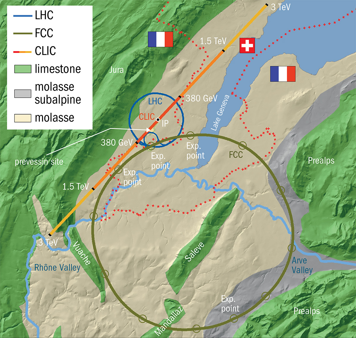
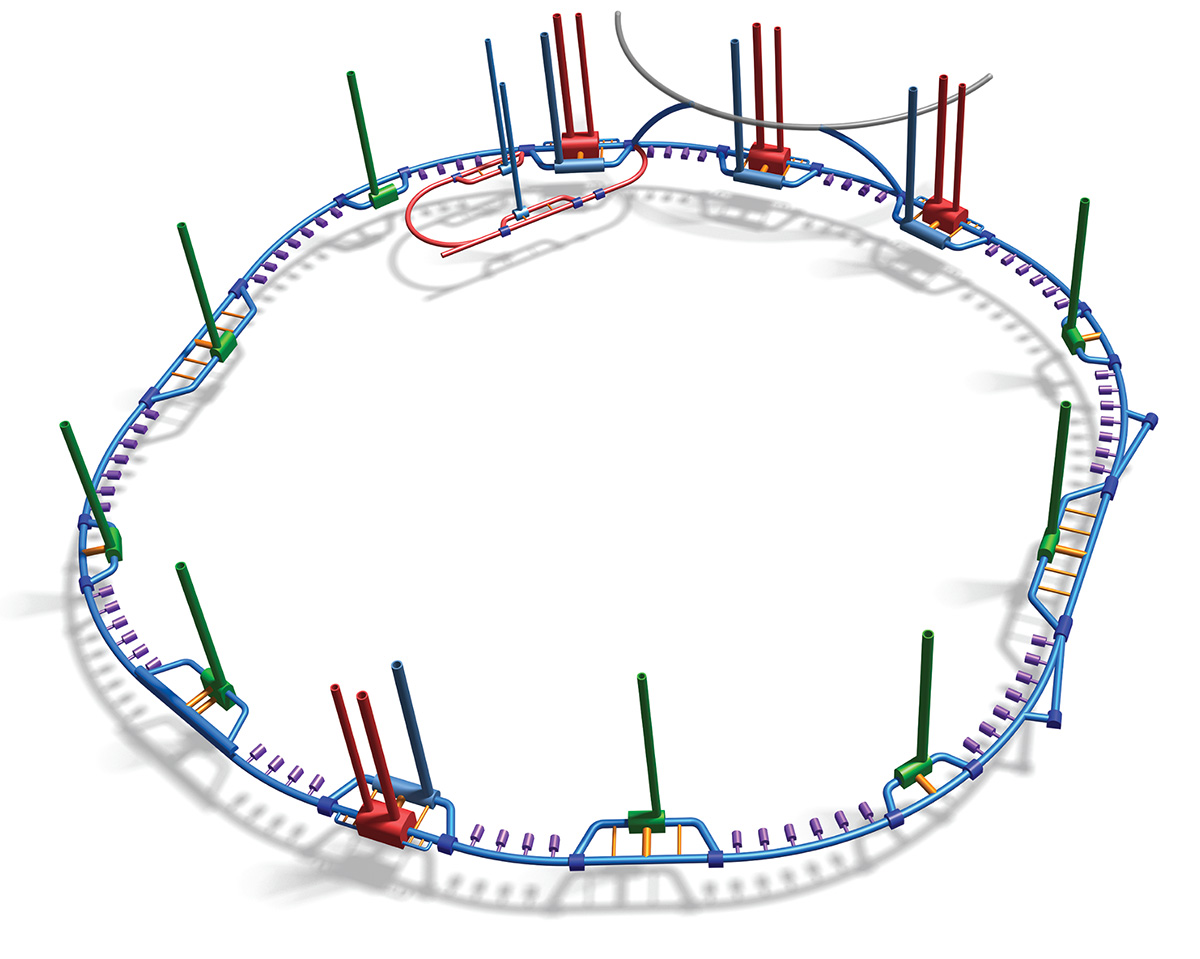
The answer to CERN’s question in 2012 was that a (quasi-)circular tunnel up to 100 km long could be built near Geneva (figure 1). This will be confirmed with further site investigations to verify the design assumptions and optimise a layout for the new machine. The FCC study considers two potential high-energy accelerators: hadron–hadron and electron–positron, and the FCC would consist of a series of arcs and straight sections (figure 2). Depending on the choice of a future collider, civil-engineering designs for FCC and/or CLIC will need to be developed further. Although the challenges between the two studies differ, the processes and tools used will be similar.
Optimising the alignment
Having determined the FCC’s feasibility, CERN’s civil engineers started designing the optimal route of the tunnel. Geology and topography are the key constraints on the tunnel position. Two alignment options were under consideration in 2012, both 80 km long, one located under the Jura Mountains and the other in the Geneva basin. When the FCC study officially kicked off in 2014, they were reviewed alongside a 47 km-circumference option fully excavated in the molasse.
Experience of tunnelling through Jura limestone during construction of the Large Electron Positron collider (LEP; from which the LHC inherited many of its tunnels) convinced civil engineers to discard the Jura option. Mining through the karstic limestone caused several delays and costly repairs after water and sediment flowed into the tunnel (see The greatest lepton collider). To this day, intensive maintenance works are needed between sectors 3 and 4 of the LHC tunnel and this has led to machine shutdowns lasting as long as two weeks.
By 2016, the proposed length of the FCC had increased to between 80 and 100 km to achieve higher energies with two alignments under consideration: intersecting (which crosses the LHC in plan view) and non-intersecting. The former is the current baseline design. The tunnel is located primarily in the competent molasse rock and avoids the problematic Jura limestone and the Prealps. However, it does pass through the Mandallaz limestone formation and also has to cross under Lake Geneva. To deal with the wealth of topographical, geological and environmental data relevant for a 100 km ring, CERN embarked on an innovative tunnel optimisation tool (TOT) that would let us assess a multitude of alignment options in a fraction of the time (see CERN’s tunnel optimisation tool).
CERN’s tunnel optimisation tool
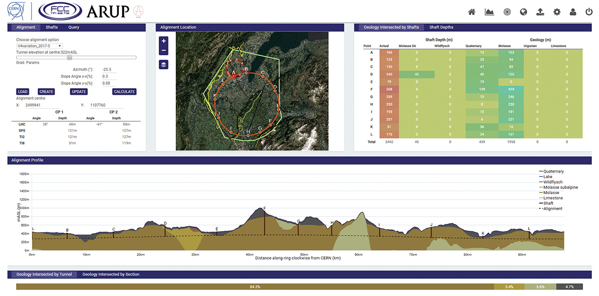
In 2014, with the help of UK-based engineering consultancy Arup, CERN developed the tunnel optimisation tool (TOT) to integrate project requirements and data into a geospatial model.The web-based tool allows the user to digitally move the FCC tunnel, change its size, shape and depth and see, in real-time, the impacts of the changes on the design. Geology, surface constraints and environmentally protected areas are visualised, and parameters such as plane inclinations and tunnel depth can be changed at the click of a mouse. The tool warns users if certain limits are exceeded or obstacles are encountered, for example, if a shaft is in the middle of Lake Geneva! When it was built, TOT was the first of its kind within the industry. It has cut the cost of the civil-engineering design and has provided us with the flexibility to meet changing requirements to ultimately deliver a better project. The success of TOT led to its replication for CLIC and the International Linear Collider (ILC) under consideration in Japan. Recently, a TOT was built by Arup to quickly and cheaply assess a range of alignments for a 3 km tunnel under the ancient Stonehenge heritage site in the UK.
The alignment of the FCC tunnel has been optimised based on three key criteria at this stage: geology (building in the competent molasse rock wherever possible); shaft depth (minimising the depth of shafts); and surface sites (choosing locations that minimise disruption to residents and the environment).
Despite the best efforts to avoid the risky Jura Mountains, the geology is not perfect. The Prealps region has complex, faulted geology and it is uncertain which layers the tunnel will cross. Cracks or faults, caused by tectonic movements of the Alps and Jura, can occur in the molasse and limestone. Excavation through Mandallaz limestone can lead to similar issues encountered during LEP’s construction. Large, high-pressure inflows can be difficult to remedy, expensive and can create delays in the programme.

To minimise the depth of the shafts, the entire FCC ring sits in an inclined plane with different heights above sea level around the tunnel. Modelling a range of alignment options at different locations and with different tunnel inclinations, constrained by the spacing requirements of the experiments, it turned out that one shaft was 558 m deep in the baseline design. The team therefore decided to replace the vertical shaft with an inclined tunnel (15% slope) to pop out the side of the mountain.
The presence of Lake Geneva influences the overall depth of the FCC, and the tunnel optimisation tool tells us that it isn’t possible to avoid tunnelling under the lake within the study boundary. Modern tunnelling techniques open up different options for crossing the lake, instead of simply digging deeper until we reach the rock (figure 3). Several options were considered, even including an option to build a hybrid particle accelerator-road tunnel in an immersed tube tunnel (which was later scrapped because of potential vibrations caused by traffic disrupting the beamline). The current design compromises on a mid-depth tunnel passing through the permeable moraines on the lake bed.
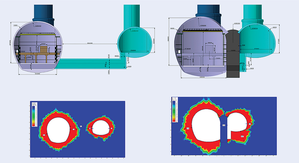
At the bottom of some of the FCC shafts are large experimental caverns with spans of up to 35 m. To determine the best arrangement for experimental and service caverns, Amberg Engineering carried out a stress analysis (figure 4). Although for data-acquisition purposes it is often desirable to have the two caverns as close as possible to each other, the analysis showed that it would be prohibitively expensive to build a 10 m concrete wall between the caverns. The cheaper option is to use the existing rock as a natural pillar, which would require a minimum spacing of 45 m.
Tunnelling inevitably disturbs the surrounding area. The beamline of the LHC is incredibly sensitive and can detect even the smallest vibrations from the outside world. This was a potential issue for construction works currently taking place for the High-Luminosity LHC project. The contractor had to improvise and modify a standard diesel excavator with an electric motor to eliminate vibrations from the engine. The programme was also adapted so that only the shafts were constructed during operation of the LHC, leaving the more disruptive cavern construction until the start of the current shutdown.
Securing the future
CERN currently has 83 km of underground structures. The FCC would add over 100 km of tunnels, 3720 m of shafts, 26 caverns (not including junction caverns), 66 alcoves and with up to 30 km between the Meyrin campus and the furthest site. The estimated civil-engineering cost for FCC (carried out by ILF Consulting Engineers) is approximately 6 billion Swiss Francs – 45% for tunnels and the rest for shafts, caverns and surface facilities – and benefits from significant advances in tunnelling technology since the LEP-tunnel days (see Advances in civil engineering since the LEP days).
Advances in civil engineering since the LEP days
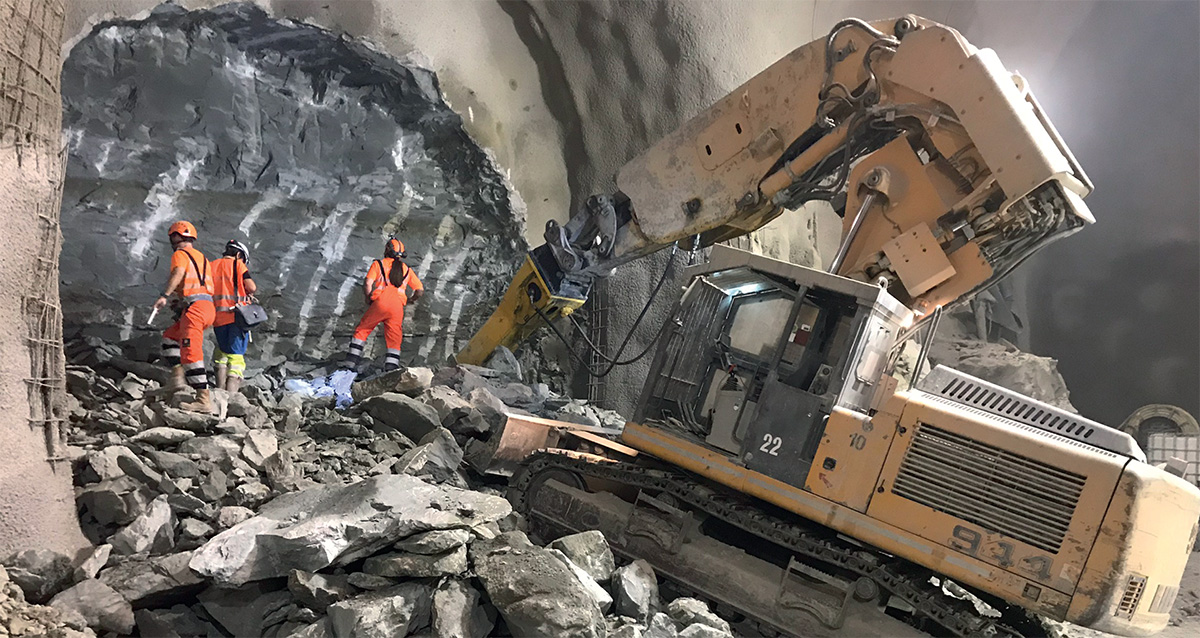
It has been almost 35 years since three tunnel boring machines (TBMs) set off to carve out the 27 km-long hole that would house LEP and, later, the LHC. Contrary to the recent claims of tech entrepreneur Elon Musk, the technology used to construct modern tunnels has been quietly and rapidly advancing since the construction of LEP, providing a faster, safer and more versatile way to build tunnels. TBMs act as a mobile factory that simultaneously excavates rock from the face and builds a tunnel lining from prefabricated segments behind it. The outer shield of the machine protects workers from falling rock, making sure they are never working in unsupported ground.
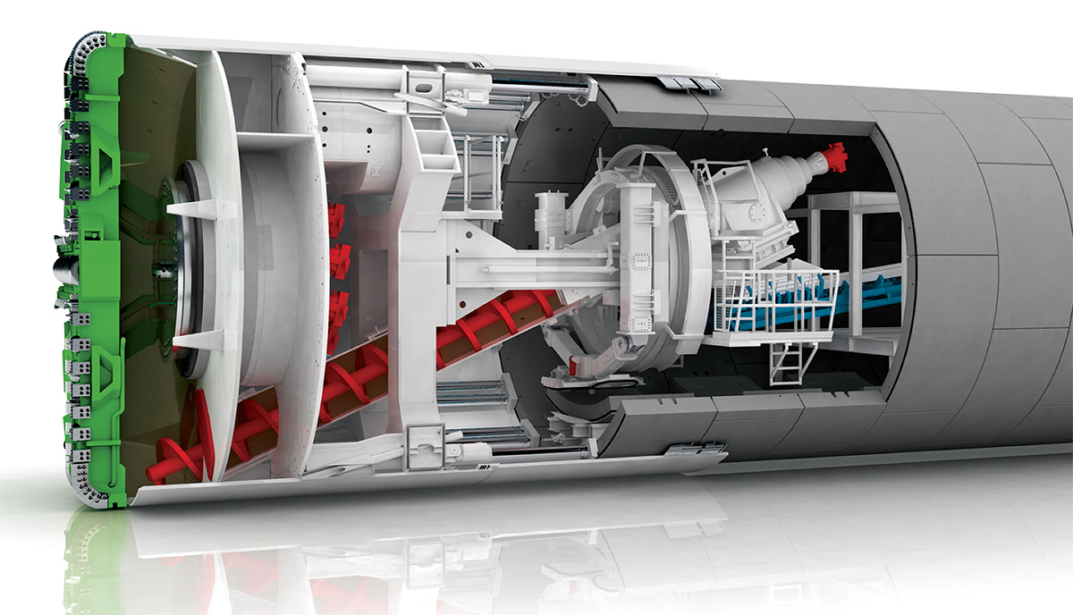
One of the main advances in TBM technology is their ability to cope in variable ground conditions. Most of the LEP tunnels were constructed in dry, competent rock, meaning the excavation face needed little support to stand up. Underneath the Jura Mountains, however, pockets of water and soil form where the limestone dissolves into karsts. When a TBM hits this, the water can flow into the tunnels, causing flooding and, at worst, tunnel collapse. Modern TBMs come with a variety of face-support measures, including earth-pressure balance machines that use the excavated soil to push back against the excavated face for support. Herrenknecht’s Mixshield TBM (above) could be used to tunnel the FCC under Lake Geneva, where water-bearing moraines are encountered.
Segmental linings can be constructed off-site in a factory, improving quality, speed and safety. The segments are assembled in the rear of the TBM immediately after excavation. The segments can be fitted with a rubber gasket, which provides a waterproof seal, eliminating the need for the traditional secondary lining. Across the 100 km of the FCC, this will lead to substantial cost savings.
Seismic and sonic scanners can be mounted to the front of the TBM, allowing operators to detect voids or obstacles up to 40 m ahead and adjust their approach accordingly. Probe drilling and pre-support measures can also be implemented from within the machine, meaning that the mining crew is safe and minimising delays to the construction programme.
For vertical shafts, the vertical shaft sinking machine and shaft boring machine are the latest technological breakthroughs, taking all the technology of a TBM and standing it on its end. The giant rig hangs off a crane and excavates below the platform, whilst building a lining above it. The machine can even work underwater to stabilise the shafts during construction.
Traditional tunnelling techniques, which are useful for creating non-standard shapes or smaller tunnels like the experimental caverns in FCC, have come a long way, too. These aren’t the normal sticks of dynamite you see in films or cartoons – highly stable explosives are slotted precisely in holes using a giant rig with multiple arms for speed. The electric detonators can be configured to the millisecond for complex patterns of explosions that give tunnellers precise control of the shape, speed and quality of the excavation.
The safety of the underground areas is critical to ensure the safe and continued operation of the experiments, and CERN has developed advanced tools to inspect the structures – some of which are more than 60 years old. Manually inspecting the condition of the structures on the scale of the FCC will become extremely challenging. We are therefore developing new technologies that will allow us to monitor the condition of the tunnels remotely. Currently, teams are testing out how fibre-optic cables can be attached to the concrete linings to measure movements over time, and developing and training algorithms to be able to spot and characterise faults in the tunnel lining. In the future, the software will be able to measure these faults and compare the changes with previous inspections to assess how they have progressed. To capture these images, a Tunnel Inspection Machine, which runs on the monorail in the roof of the LHC, and a floor-roving inspection robot have both been tested to collect images and data, even when the tunnel is not safe for humans. These images can be rebuilt in a 3D environment and viewed through a virtual-reality headset.
Projects like the FCC and CLIC are not just exciting for physicists. For civil engineers they represent challenges that demand new ideas and technology. At the annual World Tunnel Congress, attended by more than 2000 leading tunnel and underground-space experts, CERN’s FCC has already generated great interest. If approved, it would require the largest construction projects science has ever seen, bequeathing a tunnel that would serve fundamental exploration into the next century.