Besides the intrinsic worth of the knowledge that it generates, particle physics often acts as a trailblazer in developing cutting-edge technologies in the fields of accelerators, detectors and computing. These technologies, and the human expertise associated with them, find applications in a variety of areas, including the biomedical field, and can have a societal impact going way beyond their initial scope and expectations.
This webinar will introduce the knowledge-transfer goals of CERN, give an overview of the Laboratory’s medical-applications-related activities and give examples of the impact of CERN technologies on medtech: from hadrontherapy to medical imaging, flash radiotherapy, computing and simulation tools. It will also touch upon the challenges of transferring the technologies and know-how from CERN to the medtech industry and medical research.
Dr Manuela Cirilli is the deputy group leader of CERN’s Knowledge Transfer (KT) group, whose mission is to maximise the impact of CERN on society by creating opportunities for the transfer of the Laboratory’s technologies and know-how to fields outside particle physics. Manuela leads the Medical Applications section of the KT group and chairs the CERN Medical Applications Project Forum. She has an academic background in particle physics and science communication. In 1997, she started working on the NA48 experiment at CERN, designed to measure CP violation in the kaon system. In 2001, she began working on the construction, commissioning and calibration of the precision muon chambers of the ATLAS experiment at the LHC, until she joined CERN’s KT group in 2010.
In parallel to her career, Manuela has been actively engaging in science communication and popularisation since the early 2000s.
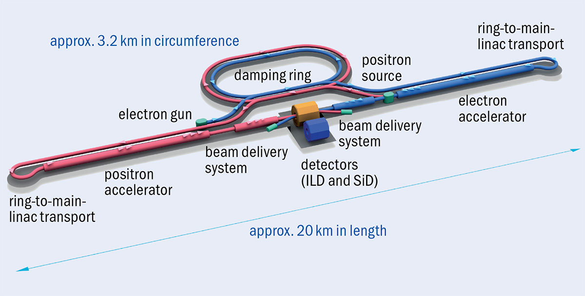
The International Linear Collider (ILC) is a proposed electron–positron linear collider with a Higgs factory operating at a centre-of-mass energy of 250 GeV (ILC250) as a first stage. Its electron and positron beams can be longitudinally polarised, and the accelerator may be extended to operate at 500 GeV up to 1 TeV, and possibly beyond. In addition, the unique time structure of the ILC beams (which would collide at short bursts of 1312 bunches with 0.554 ms spacing at a frequency of 5 Hz) places much less stringent requirements on readout speed and radiation hardness than conditions at the LHC detectors. This allows the use of low-mass tracking and high-granularity sensors in the ILC detectors, giving unprecedented resolution in jet-energy measurements. It also results in an expected data rate of just a few GB/s, allowing collisions to be recorded without a trigger.
ILC250 primarily targets precision measurements of the Higgs boson (see Targeting a Higgs factory). However, fully exploiting these measurements demands substantial improvement in our knowledge about many other Standard Model (SM) observables. Here, ILC250 opens three avenues: the study of gauge-boson pair-production and fermion pair-production at 250 GeV; fermion-pair production at effective centre-of-mass energies lowered to about 91.2 GeV by prior emission of photons (radiative returns to the Z pole); and operation of the collider at both the Z pole and the WW threshold. In all of these cases, the polarisation of the electron and positron beams (at polarisations up to 80% and 30%–60%, respectively) boosts the statistical power of many measurements by factors between 2.5 (for Higgs measurements) and 10 (at the Z pole), thanks to the ability to exploit observables such as left–right asymmetries of production cross-sections. These additional polarisation-dependent observables are also essential to disentangle the unavoidable interference between Z and γ exchange in fermion pair-production at energies above the Z pole, enabling access to the chiral couplings of fermions to the Z and the photon. Broadly speaking, the polarised beams and the high luminosity of ILC250 will lead to at least one order of magnitude improvement over the current knowledge for many SM precision observables.
Other important inputs when interpreting Higgs measurements are charged triple-gauge couplings (TGCs), which are also probes of physics beyond the SM. ILC250 will measure these 100 times more precisely than LEP, with a further factor-of-two improvement possible at the higher-energy stage ILC500. These numbers refer to the case of extracting simultaneously all three TGCs relevant in SM effective field theory, which is currently the most favoured framework for the interpretation of precision Higgs-boson data, whereas TGC results from the LHC assume that only one of these couplings deviates from its SM value at a time. With both beams polarised and with full control over the orientation of the polarisation vectors, all 28 TGC parameters that exist in the most general case can potentially be determined simultaneously at the ILC.
Z-pole physics
Classic electroweak precision observables refer to the Z pole. ILC250 will produce about 90 million visible Z events via radiative return, which is about five times more than at LEP and 100 times more than SLC. Thanks to the polarised beams, these data will allow a direct measurement of the asymmetry Ae between the left- and right-handed electron’s coupling to the Z boson with 10 times better accuracy than today, and enable the asymmetries Af of the final-state fermions to the Z to be directly extracted. This is quite different from the case of unpolarised beams, where only the product Ae Af can be accessed. Compared to LEP/SLC results, the Z-pole asymmetries can be improved by typically a factor of 20 using only the radiative returns to the Z at ILC250. This would settle beyond doubt the long-standing question of whether the 3σ tension between the weak mixing-angle extractions from SLC and LEP originates from physics beyond the SM. With a few minor modifications, the ILC can also directly operate at the Z pole, improving fermion asymmetries by another factor 6 to 25 with respect to the radiative-return results.
The higher integrated luminosity of the ILC will provide new opportunities to search for physics beyond the SM
At energies above the Z pole, di-fermion production is sensitive to hypothetical, heavy siblings of the Z boson (so-called Z′ bosons) and to four-fermion operators, i.e. contact-interaction-like parametrisations of yet unknown interactions. ILC250 could indirectly discover Z′ particles with masses up to 6 TeV, while ILC1000 could extend the reach to 18 TeV. For contact interactions, depending on the details of the assumed model, compositeness scales of up to 160 TeV can be probed at ILC250, and up to nearly 400 TeV at ILC1000.
Direct searches for new physics
At first glance, it might seem that direct searches at ILC250 offer only a marginal improvement over LEP, which attained a collision energy of 209 GeV. Nevertheless, the higher integrated luminosity of the ILC (about 2000 times higher than LEP’s above the WW threshold), its polarised beams, much-improved detectors, and triggerless readout will provide new opportunities to search for physics beyond the SM. For example, ILC250 will improve on LEP searches for a new scalar particle produced in association with the Z boson by over an order of magnitude. Another example of a rate-limited search at LEP is the supersymmetric partner of the tau lepton, the tau slepton. In the most general case, tau-slepton masses above 26.3 GeV are not excluded, and in this case no improvement from HL-LHC is expected. The ILC, with its highly-granular detectors covering angles down to 6 mrad with respect to the collision axis, has the ability to cover masses up to nearly the kinematic limit of half the collision energy, also in the experimentally most difficult parts of the parameter space.
The absence of discoveries of new high-mass states at the LHC has led to increased interest in fermionic “Z-portal” models, with masses of dark-matter particles below the electroweak scale. A dark photon, for example, could be detected via its mixing with SM photons. In searching for such phenomena, ILC250 could cover the region between the reach of the B-factories, which is limited to below 10 GeV, and the LHC experiments, which start searching in a range above 150 GeV.
The ILC’s Higgs-factory stage will require only about 40% of the tunnel length available at the Kitakami Mountains in northern Japan, which is capable of housing a linear collider at least 50 km long. This is sufficient to reach a centre-of-mass energy of 1 TeV with current technology by extending the linacs and augmenting power and cryogenics. The upgrade to ILC500 is expected to cost approximately 60% of the ILC250 cost, while going to 1 TeV would require an estimated 100% of the ILC250 cost, assuming a modest increase of the accelerating gradient over what has been achieved (CERN Courier November/December 2020 p35). These upgrades offer the opportunity to optimise the exact energies of the post-Higgs-factory stages according to physics needs and technological advances.
ILC at higher energies
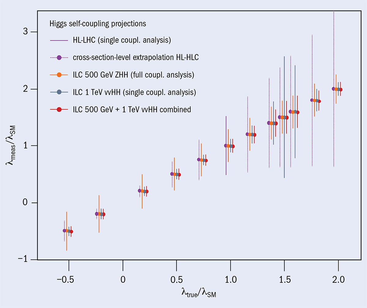
ILC500 targets the energy range 500–600 GeV, which would improve the precision on Higgs-boson couplings typically by a factor of two compared to ILC250 and on charged triple-gauge couplings by a factor of three to four. It would also offer optimal sensitivity in three important measurements. The first is the electroweak couplings of the top quark, for which a variety of new-physics models predict deviations for instance in its coupling to the Z (see “Model sensitivity” figure). The second is the Higgs self-coupling λ from double Higgs-strahlung (e+e–→ ZHH): while ILC500 could reach a precision of 27% on λ, at 1 TeV a measurement based on vector-boson fusion (VBF) reaches 10%. These numbers assume that λ takes the value predicted by the SM. However, the situation can be quite different if λ is larger, as is typically required by models of baryogenesis, and only the
combination of double Higgs-strahlung and VBF-based measurements can guarantee a precision of at least 10–20% for any value of λ (see “Higgs self-coupling” figure). A third physics target is the top-quark Yukawa coupling, for which a precision of 6.3% is projected at ILC500, 3.2% at 550 GeV and 1.6% at 1 TeV.
While ILC250 has interesting discovery potential in various rate-limited searches, ILC500 extends the kinematic reach significantly beyond LEP. For instance, in models of supersymmetry that adhere to naturalness, the supersymmetric partners of the Higgs boson (the higgsinos) must have masses that are not too far from the Z or Higgs bosons, typically around 100 to 300 GeV. While the lower range of these particles is already accessible at ILC250, the higher energy stages of the ILC will be able to cover the remainder of this search space. The ILC is also able to reconstruct decay chains when the mass differences among higgsinos are small, which is a challenging signature for the HL-LHC.
The ILC is the only future collider that is currently being discussed at the government level, by Japan, the US and various countries in Europe. It is also the most technologically established proposal, its cutting edge radio-frequency cavities already in operation at the European XFEL. The 2020 update of the European strategy for particle physics also noted that, should an ILC in Japan go ahead, the European particle-physics community would wish to collaborate. Recently, an ILC international development team was established to prepare for the creation of the ILC pre-laboratory, which will make all necessary technical preparations before construction can begin. If intergovernmental negotiations are successful, the ILC could undergo commissioning as early as the mid-2030s.
The ability to collide high-energy beams of hadrons under controlled conditions transformed the field of particle physics. Until the late 1960s, the high-energy frontier was dominated by the great proton synchrotrons. The Cosmotron at Brookhaven National Laboratory and the Bevatron at Lawrence Berkeley National Laboratory were soon followed by CERN’s Proton Synchrotron and Brookhaven’s Alternating Gradient Synchrotron, and later by the Proton Synchrotron at Serpukov near Moscow. In these machines protons were directed to internal or external targets in which secondary particles were produced.
The kinematical inefficiency of this process, whereby the centre-of-mass energy only increases as the square root of the beam energy, was recognised from the outset. In 1943, Norwegian engineer Rolf Widerøe proposed the idea of colliding beams, keeping the centre of mass at rest in order to exploit the full energy for the production of new particles. One of the main problems was to get colliding beam intensities high enough for a useful event rate to be achieved. In the 1950s the prolific group at the University of Wisconsin Midwestern Universities Research Association (MURA), led by Donald Kerst, worked on the problem of “stacking” particles, whereby successive pulses from an injector synchrotron are superposed to increase the beam intensity. They mainly concentrated on protons, where Liouville’s theorem (which states that for a continuous fluid under the action of conservative forces the density of phase space cannot be increased) was thought to apply. Only much later, ways to beat Liouville and to increase the beam density were found. At the 1956 International Accelerator Conference at CERN, Kerst made the first proposal to use stacking to produce colliding beams (not yet storage rings) of sufficient intensity.
At that same conference, Gerry O’Neill from Princeton presented a paper proposing that colliding electron beams could be achieved in storage rings by making use of the natural damping of particle amplitudes by synchrotron-radiation emission. A design for the 500 MeV Princeton–Stanford colliding beam experiment was published in 1958 and construction started that same year. At the same time, the Budker Institute for Nuclear Research in Novosibirsk started work on VEP-1, a pair of rings designed to collide electrons at 140 MeV. Then, in March 1960, Bruno Touschek gave a seminar at Laboratori Nazionali di Frascati in Italy where he first proposed a single-ring, 0.6 m-circumference 250 MeV electron–positron collider. “AdA” produced the first stored electron and positron beams less than one year later – a far cry from the time it takes today’s machines to go from conception to operation! From these trailblazers evolved the production machines, beginning with ADONE at Frascati and SPEAR at SLAC. However, it was always clear that the gift of synchrotron-radiation damping would become a hindrance to achieving very high energy collisions in a circular electron–positron collider because the power radiated increases as the fourth power of the beam energy and the inverse fourth power of mass, so is negligible for protons compared with electrons.
A step into the unknown
Meanwhile, in the early 1960s, discussion raged at CERN about the next best step for particle physics. Opinion was sharply divided between two camps, one pushing a very high-energy proton synchrotron for fixed-target physics and the other using the technique proposed at MURA to build an innovative colliding beam proton machine with about the same centre-of-mass energy as a conventional proton synchrotron of much larger dimensions. In order to resolve the conflict, in February 1964, 50 physicists from among Europe’s best met at CERN. From that meeting emerged a new committee, the European Committee for Future Accelerators, under the chairmanship of one of CERN’s founding fathers, Edoardo Amaldi. After about two years of deliberation, consensus was formed. The storage ring gained most support, although a high-energy proton synchrotron, the Super Proton Synchrotron (SPS), was built some years later and would go on to play an essential role in the development of hadron storage rings. On 15 December 1965, with the strong support of Amaldi, the CERN Council unanimously approved the construction of the Intersecting Storage Rings (ISR), launching the era of hadron colliders.
On 15 December 1965, the CERN Council unanimously approved the construction of the ISR, launching the era of hadron colliders
First collisions
Construction of the ISR began in 1966 and first collisions were observed on 27 January 1971. The machine, which needed to store beams for many hours without the help of synchrotron-radiation damping to combat inevitable magnetic field errors and instabilities, pushed the boundaries in accelerator science on all fronts. Several respected scientists doubted that it would ever work. In fact, the ISR worked beautifully, exceeding its design luminosity by an order of magnitude and providing an essential step in the development of the next generation of hadron colliders. A key element was the performance of its ultra-high-vacuum system, which was a source of continuous improvement throughout the 13 year-long lifetime of the machine.
For the experimentalists, the ISR’s collisions (which reached an energy of 63 GeV) opened an exciting adventure at the energy frontier. But they were also learning what kind of detectors to build to fully exploit the potential of the machine – a task made harder by the lack of clear physics benchmarks known at the time in the ISR energy regime. The concept of general-purpose instruments built by large collaborations, as we know them today, was not in the culture of the time. Instead, many small collaborations built experiments with relatively short lifecycles, which constituted a fruitful learning ground for what was to come at the next generation of hadron colliders.
There was initially a broad belief that physics action would be in the forward directions at a hadron collider. This led to the Split Field Magnet facility as one of the first detectors at the ISR, providing a high magnetic field in the forward directions but a negligible one at large angle with respect to the colliding beams (the nowadays so-important transverse direction). It was with subsequent detectors featuring transverse spectrometer arms over limited solid angles that physicists observed a large excess of high transverse momentum particles above low-energy extrapolations. With these first observations of point-like parton scattering, the ISR made a fundamental contribution to strong-interaction physics. Solid angles were too limited initially, and single-particle triggers too biased, to fully appreciate the hadronic jet structure. That feat required third-generation detectors, notably the Axial Field Spectrometer (AFS) at the end of the ISR era, offering full azimuthal central calorimeter coverage. The experiment provided evidence for the back-to-back two-jet structure of hard parton scattering.
For the detector builders, the original AFS concept was interesting as it provided an unobstructed phi-symmetric magnetic field in the centre of the detector, however, at the price of massive Helmholtz coil pole tips obscuring the forward directions. Indeed, the ISR enabled the development of many original experimental ideas. A very important one was the measurement of the total cross section using very forward detectors in close proximity to the beam. These “Roman Pots”, named for their inventors, made their appearance in all later hadron colliders, confirming the rising total pp cross section with energy.
It is easy to say after the fact, still with regrets, that with an earlier availability of more complete and selective (with electron-trigger capability) second- and third-generation experiments at the ISR, CERN would not have been left as a spectator during the famous November revolution of 1974 with the J/ψ discoveries at Brookhaven and SLAC. These, and the ϒ resonances discovered at Fermilab three years later, were clearly observed in the later-generation ISR experiments.
SPS opens new era
However, events were unfolding at CERN that would pave the way to the completion of the Standard Model. At the ISR in 1972, the phenomenon of Schottky noise (density fluctuations due to the granular nature of the beam in a storage ring) was first observed. It was this very same noise that Simon van der Meer speculated in a paper a few years earlier could be used for what he called “stochastic cooling” of a proton beam, beating Liouville’s theorem by the fact that a beam of particles is not a continuous fluid. Although it is unrealistic to detect the motion of individual particles and damp them to the nominal orbit, van der Meer showed that by correcting the mean transverse motion of a sample of particles continuously, and as long as the statistical nature of the Schottky signal was continuously regenerated, it would be theoretically possible to reduce the beam size and increase its density. With the bandwidth of electronics available at the time, van der Meer concluded that the cooling time would be too long to be of practical importance. But the challenge was taken up by Wolfgang Schnell, who built a state-of-the-art feedback system that demonstrated stochastic cooling of a proton beam for the first time. This would open the door to the idea of stacking and cooling of antiprotons, which later led to the SPS being converted into a proton–antiproton collider.
Another important step towards the next generation of hadron colliders occurred in 1973 when the collaboration working on the Gargamelle heavy-liquid bubble chamber published two papers revealing the first evidence for weak neutral currents. These were important observations in support of the unified theory of electromagnetic and weak interactions, for which Sheldon Glashow, Abdus Salam and Steven Weinberg were to receive the Nobel Prize in Physics in 1979. The electroweak theory predicted the existence and approximate masses of two vector bosons, the W and the Z, which were too high to be produced in any existing machine. However, Carlo Rubbia and collaborators proposed that, if the SPS could be converted into a collider with protons and antiprotons circulating in opposite directions, there would be enough energy to create them.
To achieve this the SPS would need to be converted into a storage ring like the ISR, but this time the beam would need to be kept “bunched” with the radio-frequency (RF) system working continuously to achieve a high enough luminosity (unlike the ISR where the beams were allowed to de-bunch all around the ring). The challenges here were two-fold. Noise in the RF system causes particles to diffuse rapidly from the bunch. This was solved by a dedicated feedback system. It was also predicted that the beam–beam interaction would limit the performance of a bunched-beam machine with no synchrotron-radiation damping due to the strongly nonlinear interactions between a particle in one beam with the global electromagnetic field in the other beam.
A much bigger challenge was to build an accumulator ring in which antiprotons could be stored and cooled by stochastic cooling until a sufficient intensity of antiprotons would be available to transfer into the SPS, accelerate to around 300 GeV and collide with protons. This was done in two stages. First a proof-of-principle was needed to show that the ideas developed at the ISR transferred to a dedicated accumulator ring specially designed for stochastic cooling. This ring was called the Initial Cooling Experiment (ICE), and operated at CERN in 1977–1978. In ICE transverse cooling was applied to reduce the beam size and a new technique for reducing the momentum spread in the beam was developed. The experiment proved to be a big success and the theory of stochastic cooling was refined to a point where a real accumulator ring (the Antiproton Accumulator) could be designed to accumulate and store antiprotons produced at 3.5 GeV by the proton beam from the 26 GeV Proton Synchrotron. First collisions of protons and antiprotons at 270 GeV were observed on the night of 10 July 1981, signalling the start of a new era in colliding beam physics.
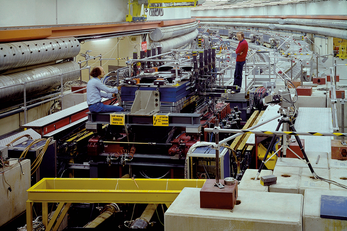
A clear physics goal, namely the discovery of the W and Z intermediate vector bosons, drove the concepts for the two main SppS experiments UA1 and UA2 (in addition to a few smaller, specialised experiments). It was no coincidence that the leaders of both collaborations were pioneers of ISR experiments, and many lessons from the ISR were taken on board. UA1 pioneered the concept of a hermetic detector that covered as much as possible the full solid angle around the interaction region with calorimetry and tracking. This allows measurements of the missing transverse energy/momentum, signalling the escaping neutrino in the leptonic W decays. Both electrons and muons were measured, with tracking in a state-of-the-art drift chamber that provided bubble-chamber-like pictures of the interactions. The magnetic field was provided by a dipole-magnet configuration, an approach not favoured in later generation experiments because of its inherent lack of azimuthal symmetry. UA2 featured a (at the time) highly segmented electromagnetic and hadronic calorimeter in the central part (down to 40 degrees with respect to the beam axis), with 240 cells pointing to the interaction region. But it had no muon detection, and in its initial phase only limited electromagnetic coverage in the forward regions. There was no magnetic field except for the forward cones with toroids to probe the W polarisation.
In 1983 the SppS experiments made history with the direct discoveries of the W and Z. Many other results were obtained, including the first evidence of neutral B-meson particle–antiparticle mixing at UA1 thanks to its tracking and muon detection. The calorimetry of UA2 provided immediate unambiguous evidence for a two-jet structure in events with large transverse energy. Both UA1 and UA2 pushed QCD studies far ahead. The lack of hermeticity in UA2’s forward regions motivated a major upgrade (UA2′) for the second phase of the collider, complementing the central part with new fully hermetic calorimetry (both electromagnetic and hadronic), and also inserting a new tracking cylinder employing novel technologies (fibre tracking and silicon pad detectors). This enabled the experiment to improve searches for top quarks and supersymmetric particles, as well as making almost background-free first precision measurements of the W mass.
Meanwhile in America
At the time the SppS was driving new studies at CERN, the first large superconducting synchrotron (the Tevatron, with a design energy close to 1 TeV) was under construction at Fermilab. In view of the success of the stochastic cooling experiments, there was a strong lobby at the time to halt the construction of the Tevatron and to divert effort instead to emulate the SPS as a proton–antiproton collider using the Fermilab Main Ring. Wisely this proposal was rejected and construction of the Tevatron continued. It came into operation as a fixed-target synchrotron in 1984. Two years later it was also converted into a proton–antiproton collider and operated at the high-energy frontier until its closure in September 2011.
A huge step was made with the detector concepts for the Tevatron experiments, in terms of addressed physics signatures, sophistication and granularity of the detector components. This opened new and continuously evolving avenues in analysis methods at hadron colliders. Already the initial CDF and DØ detectors for Run I (which lasted until 1996) were designed with cylindrical concepts, characteristic of what we now call general-purpose collider experiments, albeit DØ still without a central magnetic field in contrast to CDF’s 1.4 T solenoid. In 1995 the experiments delivered the first Tevatron highlight: the discovery of the top quark. Both detectors underwent major upgrades for Run II (2001–2011) – a theme now seen for the LHC experiments – which had a great impact on the Tevatron’s physics results. CDF was equipped with a new tracker, a silicon vertex detector, new forward calorimeters and muon detectors, while DØ added a 1.9 T central solenoid, vertexing and fibre tracking, and new forward muon detectors. Alongside the instrumentation was a breath-taking evolution in real-time event selection (triggering) and data acquisition to keep up with the increasing luminosity of the collider.
The physics harvest of the Tevatron experiments during Run II was impressive, including a wealth of QCD measurements and major inroads in top-quark physics, heavy-flavour physics and searches for phenomena beyond the Standard Model. Still standing strong are its precision measurements of the W and top masses and of the electroweak mixing angle sin2θW. The story ended in around 2012 with a glimpse of the Higgs boson in associated production with a vector boson. The CDF and DØ experience influenced the LHC era in many ways: for example they were able to extract the very rare single-top production cross-section with sophisticated multivariate algorithms, and they demonstrated the power of combining mature single-experiment measurements in common analyses to achieve ultimate precision and sensitivity.
For the machine builders, the pioneering role of the Tevatron as the first large superconducting machine was also essential for further progress. Two other machines – the Relativistic Heavy Ion Collider at Brookhaven and the electron–proton collider HERA at DESY – derived directly from the experience of building the Tevatron. Lessons learned from that machine and from the SppS were also integrated into the design of the most powerful hadron collider yet built: the LHC.
The Large Hadron Collider
The LHC had a difficult birth. Although the idea of a large proton–proton collider at CERN had been around since at least 1977, the approval of the Superconducting Super Collider (SSC) in the US in 1987 put the whole project into doubt. The SSC, with a centre-of-mass energy of 40 TeV, was almost three times more powerful than what could ever be built using the existing infrastructure at CERN. It was only the resilience and conviction of Carlo Rubbia, who shared the 1984 Nobel Prize in Physics with van der Meer for the project leading to the discovery of the W and Z bosons, that kept the project alive. Rubbia, who became Director-General of CERN in 1989, argued that, in spite of its lower energy, the LHC could be competitive with the SSC by having a luminosity an order of magnitude higher, and at a fraction of the cost. He also argued that the LHC would be more versatile: as well as colliding protons, it would be able to accelerate heavy ions to record energies at little extra cost.
The SSC was eventually cancelled in 1993. This made the case for the LHC even stronger, but the financial climate in Europe at the time was not conducive to the approval of a large project. For example, CERN’s largest contributor, Germany, was struggling with the cost of reunification and many other countries were getting to grips with the introduction of the single European currency. In December 1993 a plan was presented to the CERN Council to build the machine over a 10-year period by reducing the other experimental programmes at CERN to the absolute minimum, with the exception of the full exploitation of the flagship Large Electron Positron (LEP) collider. Although the plan was generally well received, it became clear that Germany and the UK were unlikely to agree to the budget increase required. On the positive side, after the demise of the SSC, a US panel on the future of particle physics recommended that “the government should declare its intentions to join other nations in constructing the LHC”. Positive signals were also being received from India, Japan and Russia.
In June 1994 the proposal to build the LHC was made once more. However, approval was blocked by Germany and the UK, which demanded substantial additional contributions from the two host states, France and Switzerland. This forced CERN to propose a “missing magnet” machine where only two thirds of the dipole magnets would be installed in a first stage, allowing operation at reduced energy for a number of years. Although costing more in the long run, the plan would save some 300 million Swiss Francs in the first phase. This proposal was put to Council in December 1994 by the new Director-General Christopher Llewellyn Smith and, after a round of intense discussions, the project was finally approved for two-stage construction, to be reviewed in 1997 after non-Member States had made known their contributions. The first country to do so was Japan in 1995, followed by India, Russia and Canada the next year. A final sting in the tail came in June 1996 when Germany unilaterally announced that it intended to reduce its CERN subscription by between 8% and 9%, prompting the UK to demand a similar reduction and forcing CERN to take out loans. At the same time, the two-stage plan was dropped and, after a shaky start, the construction of the full LHC was given the green light.
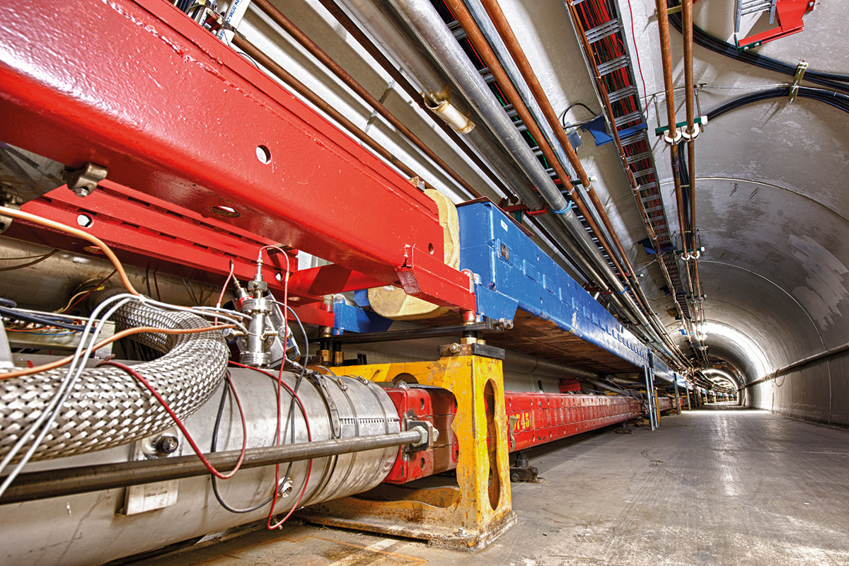
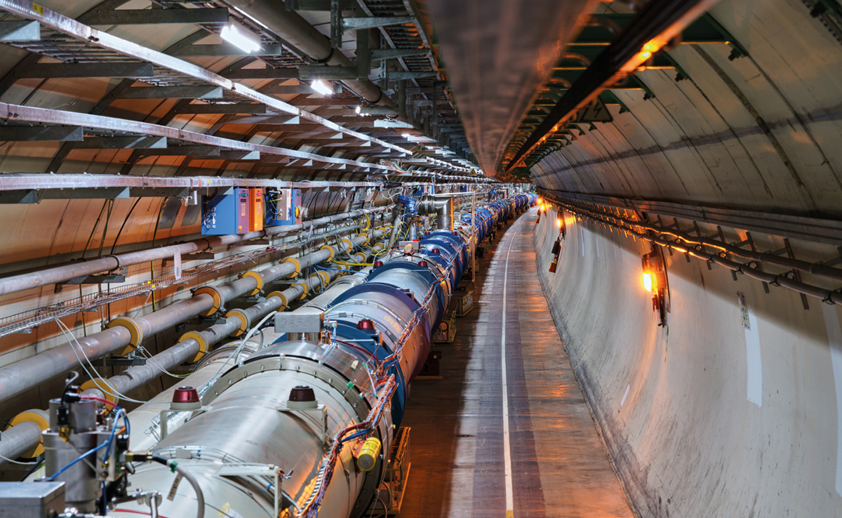
The fact that the LHC was to be built at CERN, making full use of the existing infrastructure to reduce cost, imposed a number of strong constraints. The first was the 27 km-circumference of the LEP tunnel in which the machine was to be housed. For the LHC to achieve its design energy of 7 TeV per beam, its bending magnets would need to operate at a field of 8.3 T, about 60% higher than ever achieved in previous machines. This could only be done using affordable superconducting material by reducing the temperature of the liquid-helium coolant from its normal boiling point of 4.2 K to 1.9 K – where helium exists in a macroscopic quantum state with the loss of viscosity and a very large thermal conductivity. A second major constraint was the small (3.8 m) tunnel diameter, which made it impossible to house two independent rings like the ISR. Instead, a novel and elegant magnet design, first proposed by Bob Palmer at Brookhaven, with the two rings separated by only 19 cm in a common yoke and cryostat was developed. This also considerably reduced the cost.
This journey is now poised to continue, as we look ahead towards how a general-purpose detector at a future 100 TeV hadron collider might look like
At precisely 09:30 on 10 September 2008, almost 15 years after the project’s approval, the first beam was injected into the LHC, amid global media attention. In the days that followed good progress was made until disaster struck: during a ramp to full energy, one of the 10,000 superconducting joints between the magnets failed, causing extensive damage which took more than a year to recover from. Following repairs and consolidation, on 29 November 2009 beam was once more circulating and full commissioning and operation could start. Rapid progress in ramping up the luminosity followed, and the LHC physics programme, at an initial energy of 3.5 TeV per beam, began in earnest in March 2010.
LHC experiments
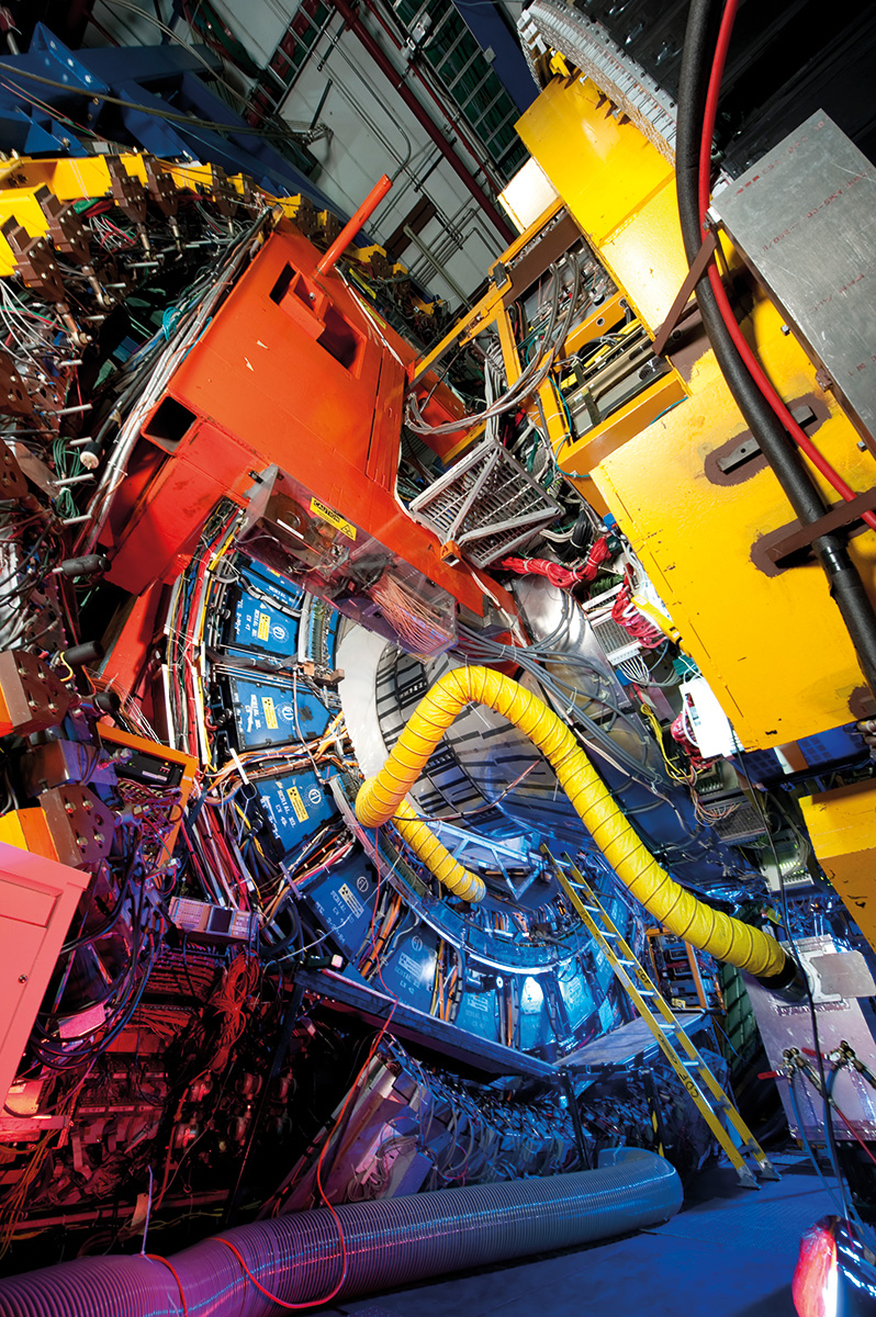
Yet a whole other level of sophistication was realised by the LHC detectors compared to those at previous colliders. The priority benchmark for the designs of the general-purpose detectors ATLAS and CMS was to unambiguously discover (or rule out) the Standard Model Higgs boson for all possible masses up to 1 TeV, which demanded the ability to measure a variety of final states. The challenges for the Higgs search also guaranteed the detectors’ potential for all kinds of searches for physics beyond the Standard Model, which was the other driving physics motivation at the energy frontier. These two very ambitious LHC detector designs integrated all the lessons learned from the experiments at the three predecessor machines, as well as further technology advances in other large experiments, most notably at HERA and LEP.
Just a few simple numbers illustrate the giant leap from the Tevatron to the LHC detectors. CDF and DØ, in their upgraded versions operating at a luminosity of up to 4 × 1032 cm–2s–1, typically had around a million channels and a triggered event rate of 100 Hz, with event sizes of 500 kB. The collaborations were each about 600 strong. By contrast, ATLAS and CMS operated during LHC Run 2 at a luminosity of 2 × 1034 cm–2s–1 with typically 100 million readout channels, and an event rate and size of 500 Hz and 1500 kB. Their publications have close to 3000 authors.
For many major LHC-detector components, complementary technologies were selected. This is most visible for the superconducting magnet systems, with an elegant and unique large 4 T solenoid in CMS serving both the muon and inner tracking measurements, and an air-core toroid system for the muon spectrometer in ATLAS together with a 2 T solenoid around the inner tracking cylinder. These choices drove the layout of the active detector components, for instance the electromagnetic calorimetry. Here again, different technologies were implemented: a novel-configuration liquid-argon sampling calorimeter for ATLAS and lead-tungstate crystals for CMS.
From the outset, the LHC was conceived as a highly versatile collider facility, not only for the exploration of high transverse-momentum physics. With its huge production of b and c quarks, it offered the possibility of a very fruitful programme in flavour physics, exploited with great success by the purposely designed LHCb experiment. Furthermore, in special runs the LHC provides heavy-ion collisions for studies of the quark–gluon plasma – the field of action for the ALICE experiment.
As the general-purpose experiments learned from the history of experiments in their field, the concepts of both LHCb and ALICE also evolved from a previous generation of experiments in their fields, which would be interesting to trace back. One remark is due: the designs of all four main detectors at the LHC have turned out to be so flexible that there are no strict boundaries between these three physics fields for them. All of them have learned to use features of their instruments to contribute at least in part to the full physics spectrum offered by the LHC, of which the highlight so far was the July 2012 announcement of the discovery of the Higgs boson by the ATLAS and CMS collaborations. The following year the collaborations were named in the citation for the 2013 Nobel Prize in Physics awarded to François Englert and Peter Higgs.
Since then, the LHC has exceeded its design luminosity by a factor of two and delivered an integrated luminosity of almost 200 fb–1 in proton–proton collisions, while its beam energy was increased to 6.5 TeV in 2015. The machine has also delivered heavy ion (lead–lead) and even lead–proton collisions. But the LHC still has a long way to go before its estimated end of operations in the mid-to-late 2030s. To this end, the machine was shut down in November 2018 for a major upgrade of the whole of the CERN injector complex as well as the detectors to prepare for operation at high luminosities, ultimately up to a “levelled” luminosity of 7 × 1034 cm–2s–1. The High Luminosity LHC (HL-LHC) upgrade is pushing the boundaries of superconducting magnet technology to the limit, particularly around the experiments where the present focusing elements will be replaced by new magnets built from high-performance Nb3Sn superconductor. The eventual objective is to accumulate 3000 fb–1 of integrated luminosity.
In parallel, the LHC-experiment collaborations are preparing and implementing major upgrades to their detectors using novel state-of-art technologies and revolutionary approaches to data collection to exploit the tenfold data volume promised by the HL-LHC. Hadron-collider detector concepts have come a long way in sophistication over the past 50 years. However, behind the scenes are other factors paramount to their success. These include an equally spectacular evolution in data-flow architectures, software and the computing approaches, and analysis methods – all of which have been driven into new territories by the extraordinary needs for dealing with rare events within the huge backgrounds of ordinary collisions at hadron colliders. Worthy of particular mention in the success of all LHC physics results is the Worldwide LHC Computing Grid. This journey is now poised to continue, as we look ahead towards how a general-purpose detector at a future 100 TeV hadron collider might look like.
Beyond the LHC
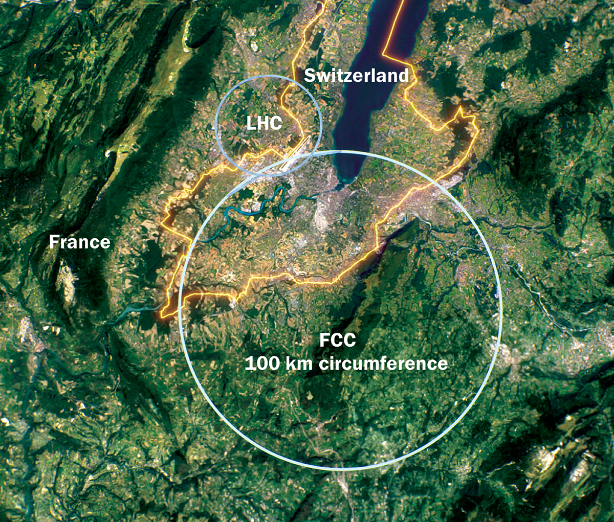
Although the LHC has at least 15 years of operations ahead of it, the question now arises, as it did in 1964: what is the next step for the field? The CERN Council has recently approved the recommendations of the 2020 update of the European strategy for particle physics, which includes, among other things, a thorough study of a very high-energy hadron collider to succeed the LHC. A technical and financial feasibility study for a 100 km circular collider at CERN with a collision energy of at least 100 TeV is now under way. While a decision to proceed with such a facility is to come later this decade, one thing is certain: lessons learned from 50 years of experience with hadron colliders and their detectors will be crucial to the success of our next step into the unknown.
The proposed 100 km-circumference Future Circular Collider (FCC) at CERN features, as a first stage, an electron–positron Higgs and electroweak factory (FCC-ee) operating at centre-of-mass energies from 91 GeV (the Z mass) to a maximum of 365 GeV (above the tt production threshold). The same tunnel is then planned to host a hadron collider (FCC-hh) operating at the highest possible energies, at least 100 TeV. The complete FCC programme, whose financial and technical feasibility is currently under study, offers unprecedented potential in terms of the reach on phenomena beyond the Standard Model (SM). The proposed Circular Electron Positron Collider project in China adopts the scheme envisioned for the FCC-ee, with a somewhat less ambitious overall physics programme.
While the original goal of a future lepton collider is the precise study of the interactions of the scalar boson discovered in 2012 at the LHC, seeking answers to open questions in particle physics requires many high-precision measurements of the other three heaviest SM particles: the W and Z electroweak bosons and the top quark. Beyond the exploration of the Higgs sector, FCC-ee offers a rich range of opportunities to indirectly and directly discover new phenomena.
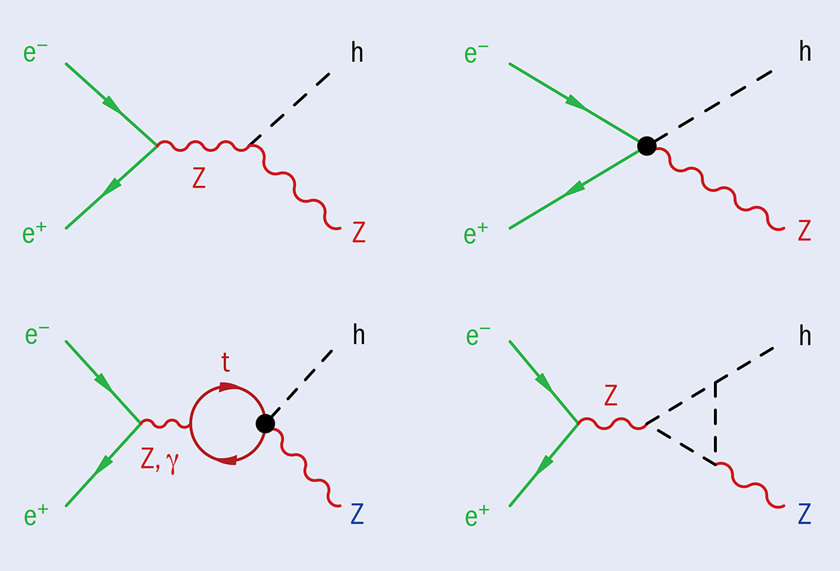
Studies of Higgs-boson interactions are prime tests of the dynamics of electroweak symmetry breaking and of the generation of elementary-particle masses. At FCC-ee, the Higgs boson will dominantly be produced by radiation off a Z boson. With around one million such e+e–→ ZH events recorded in three years of operation, a per-mil precision is targeted on the cross-section measurement. This corresponds to probing phenomena coupled to the scalar SM sector at energy scales approaching 10 TeV. The Higgsstrahlung process is, however, sensitive to gauge interactions beyond those of the Higgs boson (see “Higgs production” figure), which can themselves be affected by new physics. A robust test of the SM’s consistency will require independent experimental determination of these interactions. The precision available today is insufficient, however, and calls for new electroweak measurements to be performed.
Electroweak and top-quark precision
FCC-ee will provide these missing pieces, and much more. An unprecedented number (5 × 10¹²) of Z bosons will be produced with an exquisite knowledge of the centre-of-mass energy (100 keV or lower, thanks to the availability of transverse polarisation of the beams), thereby surpassing the precision of all previous measurements at LEP and SLC by several orders of magnitude. Uncertainties of the order of 100 keV on the Z-boson’s mass and 25 keV on its width can be achieved, as well as precisions of around 10–5on the various charged fermion couplings, and of 3 × 10⁻⁵ on the QED coupling strength αQED (mZ). Impressive numbers of pairs of tau leptons (1.7 × 10¹¹) and 1012 each of c and b quarks will be produced in Z decays, allowing order-of-magnitude improvements on tau and heavy-flavour observables compared to other planned facilities.
At the WW threshold, with 108 W bosons collected at a centre-of-mass energy of 161 GeV and threshold scans with an energy uncertainty of about 300 keV, a unique W-boson mass precision of 0.5 MeV will be reached. Meticulous measurements of di-boson production will be essential for the Higgs programme, given the gauge-symmetry relations between triple-gauge-boson and Higgs-gauge-boson interactions. Hadronic W and Z decays will also provide measurements of the QCD coupling strength with per-mil uncertainties – a factor of 10 better than the current world average.
Stepping up to a centre-of-mass energy of 350 GeV, e+e–→ tt measurements would deliver an impressive determination of the top-quark mass with 10 MeV statistical uncertainty, thanks to energy scans with a 4 MeV precision. At the highest FCC-ee energies, the determination of the top quark’s electroweak couplings, which affect Higgs processes, can be performed to sub-percent precision.
These high-precision FCC-ee measurements in the Higgs, electroweak and top-quark sectors will be sensitive to a large variety of new-physics scenarios. High-mass physics with SM couplings, for example, can be tested up to scales of the order of 50 TeV. Regardless of mass scale, mixing of new particles with known ones at the level of a few tens of ppm will also produce visible effects.
Probing new physics at the Z pole
Given that new light particles are constrained to be feebly coupled to the SM, large e+e– luminosities are needed to search for them. By examining an astounding number of Z-boson decays, FCC-ee will explore uncharted territories in direct searches for feebly coupled light states, such as heavy neutral leptons and axion-like particles. If not directly produced, the former are also probed indirectly through precision electroweak measurements.
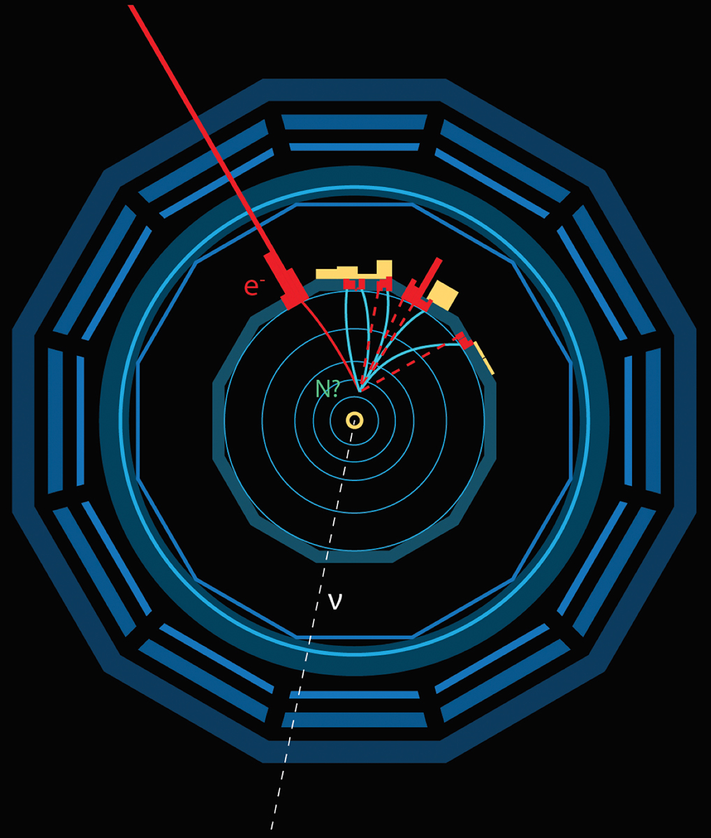
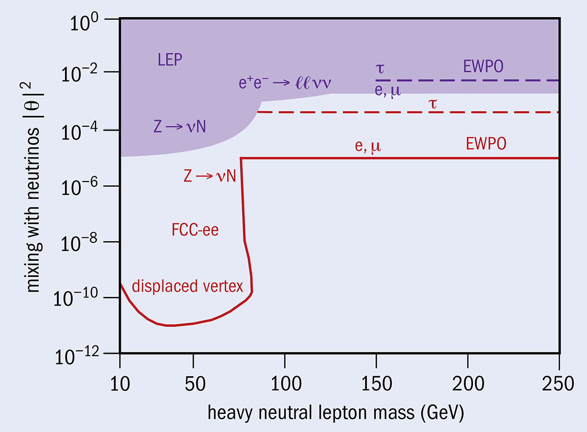
Heavy neutral leptons (N) are sterile particles, such as those invoked in neutrino mass-generation mechanisms. The mixing of these states with neutrinos would induce interactions with electroweak bosons and charged leptons, for example N¯W, NνZ or NνH. Heavy neutral leptons can have a wide range of masses and be searched for at FCC-ee, both directly and indirectly, with unparalleled reach. When heavier than the muon and mixing with either the e or µ flavours, they lower the µ → eνeνµ decay rate and affect the extraction of the Fermi constant, leading to deviations from the SM in many precision electroweak observables. When lighter than the Z boson, they could be produced in Z → νN decays. FCC-ee will bring order-of-magnitude improvements over LEP bounds in both regimes (see “Heavy neutral leptons” figure). The direct sensitivity improves even more dramatically than the indirect one: in the parameter space where N have sizeable lifetimes, displaced vertices provide a spectacular, background-free, signature (see “Discovery potential” image). This region of great interest corresponds to weak-scale leptogenesis, in which right-handed neutrinos participate in the generation of the baryon asymmetry of the universe.
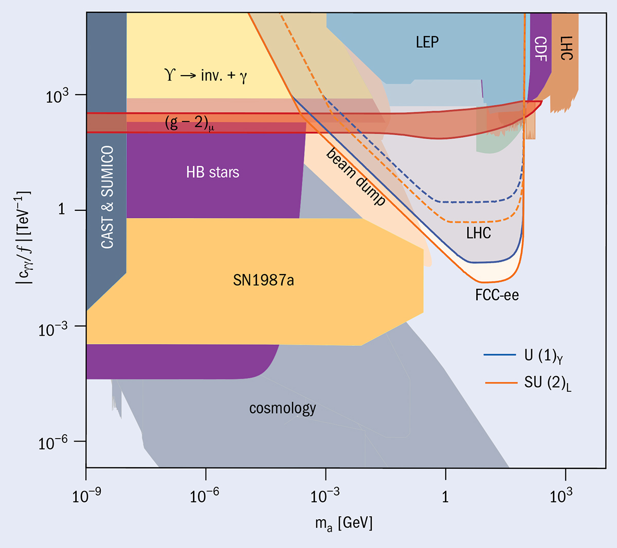
Axion-like particles (ALPs) are pseudoscalar singlets with derivative couplings to the SM, which may be generated in the breaking of global symmetries at high scales. They could contribute to the dark-matter relic abundance and, in a specific range of parameter space, provide a dynamical explanation for the absence of CP violation in the strong interaction. Having symmetry-protected masses, ALPs can be naturally light. For masses smaller than twice that of the electron, they can only visibly decay to photons. Suppressed by a potentially large scale, their couplings to the SM may be tiny. ALPs lifetimes could thus be large. A coupling to either hypercharge or weak isospin would allow them to be produced in Z-boson decays together with a photon and to decay to photon pairs. Searching for this signature, FCC-ee will probe couplings more than an order of magnitude smaller than those accessible at the LHC (see “Axion-like particles” figure). Pairs of ALPs could possibly also be produced in the decay of the Higgs boson, whose small width enhances branching fractions and allows small couplings to be probed. Producing Higgs bosons in larger numbers, hadron colliders are, however, more efficient at probing such interactions.
Towards a new frontier
The physics potential of FCC-ee clearly extends much beyond its original purpose as a Higgs and electroweak factory. Upgrading the facility to FCC-hh will require a new machine based on high-field superconducting magnets, although key parts of FCC-ee infrastructure would be usable at both colliders. Compared to the LHC, FCC-hh will collect about 10 times more integrated luminosity and increase the direct discovery reach for high-mass particles – such as Z′ or W′ gauge bosons, gluinos and squarks, and even WIMP dark matter – by a factor of around 10, up to scales of about 50 TeV. It would also serve as a giga Higgs factory, producing more than 1010 Higgs bosons during its planned 25 years of data taking, albeit not in the ultraclean collision environment of FCC-ee.
Beyond exquisite precision on Higgs-boson couplings to other SM particles, a 100 TeV proton–proton collider comes to the fore in revealing how the Higgs boson couples to itself, which is connected to the electroweak phase transition in the early universe and ultimately to the stability of the vacuum. The rate of Higgs pair-production events, which in some part occur through the Higgs self-interaction, would grow by a factor of 40 at FCC-hh with respect to the LHC and enable this unique property of the Higgs boson to be measured with a statistical accuracy reaching ±2%. Such a measurement would comprehensively explore classes of models that rely on modifying the Higgs potential to drive a strong first-order phase transition at the time of electroweak symmetry breaking, a necessary condition to induce baryogenesis.
Stepping up to an energy of 350 GeV would deliver an impressive determination of the top-quark mass
Following the highly successful model of LEP and its successor, the LHC, the integrated FCC programme offers a far-reaching particle-physics programme at the limits of known technology to significantly push the frontier of our knowledge of the fundamental particles and interactions. A conceptual design report was published in 2019, estimating that operations could begin as soon as 2040 for FCC-ee and 2065 for FCC-hh. Exploring the financial and technical feasibility of this visionary project
is one of the highest priority recommendations of the 2020 update of the European strategy for particle physics, with a decision on whether or not to proceed expected by the next strategy update towards the middle of the decade.
The Compact Linear Collider (CLIC) is conceived in its first stage to be an 11 km-long electron–positron collider operating at a centre-of-mass energy of 380 GeV. Unlike other Higgs-factory proposals that start around 240 GeV, CLIC benefits at the initial stage not only from top-quark production, but also from two Higgs-boson production modes – Higgsstrahlung (e+e–→ HZ) and WW fusion – giving extra complementary input for global interpretations of the data.
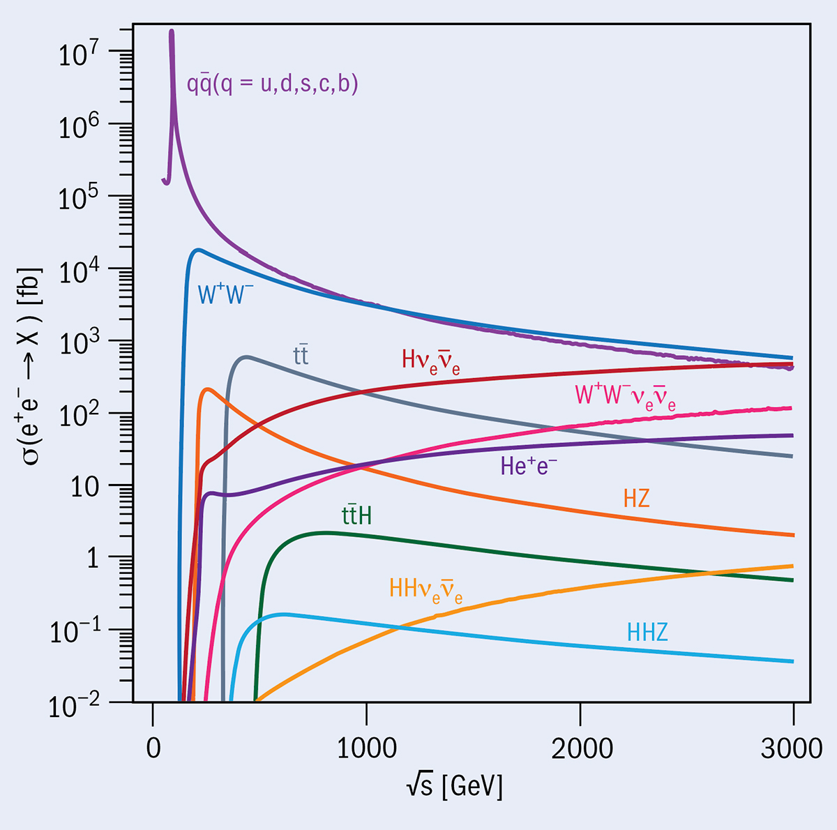
A defining feature of a linear collider is that its collision energy can be raised by extending its length. While the European strategy update recommended a circular hadron collider at the energy frontier as a long-term ambition, CLIC represents a compelling alternative were a circular machine found not to be feasible. CLIC has the potential to be extended in several stages up to 50 km and a maximum energy of 3 TeV, giving access to a wide range of physics processes (see “Multichannel” figure). Some important processes such as Higgsstrahlung production fall with energy, while others such as double-Higgs production require higher energies, and processes occurring through vector-boson fusion grow with energy. In general, the beyond-Standard-Model (BSM) sensitivity of scattering processes such as ZH, WW and two-fermion (including top-pair) production rises strongly with energy, so the higher-energy stages bring further sensitivity to potential new physics both indirectly and directly.
Lepton colliders can in general explore much closer to kinematic limits than hadron colliders
In contrast to the ILC (see ILC: beyond the Higgs), CLIC operates via a novel two-beam scheme, whereby radio-frequency power extracted from a high-current, low-energy drive beam is used to accelerate the colliding beams. Were a decision to be made to upgrade CLIC from 380 GeV to 1.5 TeV, the length of the main linacs would have to be extended to 29 km, as well as moving and adding accelerator modules. Going from an energy of 1.5 to 3 TeV, as well as further lengthening of the main linacs, a second drive-beam complex must be added. CLIC’s combination of Higgs- and top-factory running, and multi-TeV extension potential, makes it illuminating to study the physics prospects of the initial stage in parallel with those of the ultimate energy.
Higgs physics
At 380 GeV, with 1 ab–1 of integrated luminosity CLIC would produce around 160,000 Higgs bosons. This stage would enable precision determinations well beyond the HL-LHC, for example in the single-Higgs couplings to WW, ZZ, bb, and cc. Due to the known kinematic constraints in the collision environment, it also allows an absolute determination of the Higgs couplings, as opposed to the ratios accessible at the LHC. The corresponding precision on Higgs-coupling measurements is increased considerably by the enhanced statistics at 1.5 TeV, where CLIC could produce 1 million Higgs bosons with an integrated luminosity of 2.5 ab–1 as well as opening sensitivity to other processes. A linear collider like CLIC provides considerable flexibility, for example: collecting at 380 GeV 1 ab–1 in 8 years or 4 ab–1 in 13 years, as studied recently, before a possible jump to 1.5 TeV.
The 1.5 TeV energy stage gives access to two double-Higgs production mechanisms: double-Higgsstrahlung (e+e–→ ZHH) and vector-boson fusion (e+e–→ HHνeνe). Such production of Higgs-boson pairs allows the Higgs self-coupling to be probed directly. While the 1.5 TeV stage could reach a precision of –29%/+67% using a rate-only analysis, at 3 TeV an ultimate Higgs self-coupling precision of –8%/+11% is expected, also exploiting differential information. Furthermore, the ability to measure both the ZHH and HHνeνe processes allows for an unambiguous determination of the Higgs self-coupling even if it is far from its Standard Model value. Unlike indirect determinations from ZH measurements at lower Higgs-factory energies, the precision of CLIC’s direct Higgs-self-coupling measurement is largely preserved in global fits. CLIC could thus robustly verify that the Higgs self-coupling assumes the value predicted by the Standard Model, or uniquely identify the new-physics effects responsible for potential tensions with the Standard Model in Higgs observables.
Top-quark physics
CLIC is unique among the proposed electron–positron colliders in producing top-quark pairs at its initial energy stage. Electroweak couplings to third-generation fermions such as the top are particularly relevant in many BSM scenarios. Operating at the top-quark pair-production threshold of around 350 GeV would allow precise measurements of the top-quark mass and width, while cross-section and asymmetry measurements would probe the top-quark interactions. However, comprehensive exploration of top-quark couplings requires several energy stages, and spacing them widely as the CLIC baseline envisages enhances energy-dependent effects.
Electron-beam longitudinal polarisation at ±80% plays an important role in the precision programme at CLIC. Generally the polarisation significantly enhances WW-fusion processes, for example single- and double-Higgs production at higher energies; we make use of this in the baseline scenario by taking more data with left-handed electrons at the later stages. In the interpretation of Standard Model measurements, polarisation also helps to disentangle different contributions. The coupling of the top quark to the Z boson and the photon is one such example.
Indirect searches
Many observables such as cross-sections and differential distributions for WW and two-fermion production, in addition to measurements from the Higgs-boson and top-quark sectors, can be used to constrain potential new physics in the framework of effective field theory. Here, the Standard Model Lagrangian is supplemented by interaction operators of higher dimension that describe the effects of new particles. These particles could be too heavy to be produced at CLIC, but can still be probed through the effects they induce, indirectly, on CLIC observables.
For many new-physics operators, CLIC is projected to bring an order of magnitude increase in sensitivity over the HL-LHC. The 380 GeV stage already significantly enhances our knowledge of operators relating to modifications of the Higgs couplings, as well as electroweak observables such as triple-gauge couplings. The higher-energy stages are then particularly effective in probing operators that induce corrections to Standard Model predictions which grow with energy. Sensitivity to these operators allows a wide range of new-physics scenarios to be probed without reference to particular models. Comparisons performed for the 2020 update of the European strategy for particle physics show, for example, that sensitivities derived in this way to four-fermion, or two-fermion two-boson contact interactions rise very steeply with the centre-of-mass energy of a lepton collider, allowing CLIC to probe scales up to 100 TeV and beyond.
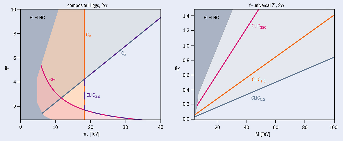
Precision measurements of Standard Model processes can also be interpreted in the context of particular BSM models, such as the broad classes of composite Higgs and top, or extra-dimension models. At CLIC this represents strong new-physics reach. For example, a 3 TeV CLIC has sensitivity to Higgs compositeness up to a scale of around 18 TeV for all values of the compositeness sector coupling strength (see “Sensitivity” figure, left), and can reach beyond 40 TeV in particularly favourable scenarios; in all cases well beyond what the HL-LHC can exclude. At high masses, a multi-TeV lepton collider such as CLIC also provides the best possible sensitivity to search for new vector bosons such as the Y-universal Z′, which has couplings to quarks and leptons that are comparable (see figure, right).
As a further example, the very high energy of CLIC, and therefore the high propagator virtuality in two-fermion production, means that high-precision differential cross-sections could reveal deviations from Standard Model predictions owing to the presence of new particles in loops. This would allow discovery or exclusion of new states, for example dark-matter candidates, with a variety of possible quantum numbers and masses in the range of several TeV.
Direct searches
Direct searches for new physics at CLIC benefit from the relatively clean collision environment and from triggerless detector readout, both of which allow searches for elusive signatures that are difficult at a hadron collider. Mono-photon final states are an example of such a signature. In simplified dark-matter models containing a dark-matter particle and a mediator, dark-matter particles can be pair-produced in association with a photon, which is observed in the detector. In the case of a scalar mediator, lepton colliders are particularly sensitive and CLIC’s reach for the mediator can exceed its centre-of-mass energy significantly. In the case where the couplings to electrons and quarks are different, e+e– and proton colliders provide complementary sensitivities.
Lepton colliders can in general explore much closer to kinematic limits than hadron colliders, and this was recently verified in several examples of pair production, including simplified supersymmetric models and doubly charged Higgs production. Supersymmetric models where the higgsino multiplet is decoupled from all other supersymmetric states can lead to charginos decaying to slightly lighter neutralinos and leaving a “disappearing track stub” signature in the detector. CLIC at 3 TeV would be sensitive to such a higgsino to masses beyond 1.1 TeV, which is what would be required for the higgsino to account for the dark-matter relic mass density.
All the above approaches can be combined to illuminate the electroweak phase transition in the early universe. Models of electroweak baryogenesis can contain new scalar particles to facilitate a strong first-order phase transition, during which the electroweak symmetry is broken. Such scalar singlet extensions of the Higgs sector can be searched for directly; and indirectly from a universal scaling of all Higgs couplings.
Having both the precision capacity of a lepton collider and also the high-energy reach of multi-TeV collisions, CLIC has strong potential beyond a Higgs factory as a discovery machine. Over the next five years CERN will maintain a level of R&D in key CLIC technologies, which are also being adapted for medical applications, such that the project could be realised in a timely way after the HL-LHC if the international community decides to take this route.
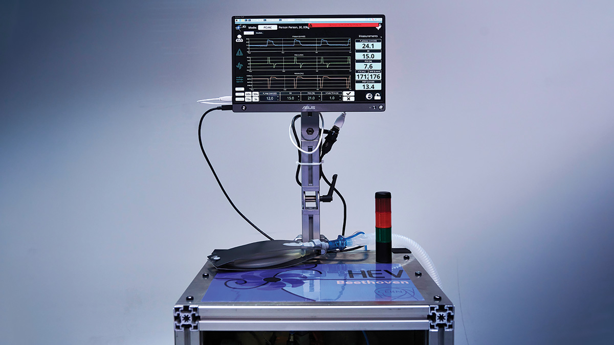
A versatile ventilator to help combat COVID-19 developed by members of the LHCb collaboration is to be re-engineered for manufacture and clinical use. The High Performance Low-cost Ventilator (HPLV) is designed to assist patients in low- and middle-income countries suffering from severe respiratory problems as a result of COVID-19. Following the award of £760,000 by UK Research and Innovation, announced in December, Ian Lazarus of the Science and Technology Facilities Council’s Daresbury Laboratory and co-workers aim to produce and test plans for the creation of an affordable, reliable and easy to operate ventilator that does not rely so heavily on compressed gases and mains electricity supply.
“I am proud to be leading the HPLV team in which we have brought together experts from medicine, science, engineering and knowledge transfer with a shared goal to make resilient high-quality ventilators available in areas of the world that currently don’t have enough of them,” said Lazarus in a press release.
While the majority of people who contract COVID-19 suffer mild symptoms, in some cases the disease can cause severe breathing difficulties and pneumonia. For such patients, the availability of ventilators that deliver oxygen to the lungs while removing carbon dioxide is critical. Commercially available ventilators are typically costly, require considerable experience to use, and often rely on the provision of high-flow oxygen and medically pure compressed air, which are not readily available in many countries.
The HPLV takes as its starting point the High Energy physics Ventilator (HEV), which was inspired by an initiative at the University of Liverpool and developed at CERN in March 2019 during the first COVID-19 lockdown. The idea emerged when physicists and engineers in LHCb’s vertex locator (VELO) group realised that the systems which are routinely used to supply and control gas at desired temperatures and pressures in particle-physics detectors are well matched to the techniques required to build and operate a ventilator (CERN Courier May/June 2020 p8). HPLV will see the hardware and software of HEV adapted to make it ready for regulatory approval and manufacture. Project partners at the Federal Institute of Rio de Janeiro in Brazil – in collaboration with CERN, the University of Birmingham, the University of Liverpool and the UK’s Medical Devices Testing and Evaluation Centre – will now identify difficulties encountered when ventilating patients and pass that information to the design team to ensure that the HPLV is fit for purpose.
“We warmly welcome the HPLV initiative, and look forward to working together with the outstanding HPLV team for our common humanitarian goal,” says Paula Collins, who co-leads the HEV project with CERN and LHCb colleague Jan Buytaert. The HPLV is one of several HEV offshoots involving 25 academic partners, she explains. “In December we also saw the first HEV prototypes to be constructed outside CERN, at the Swiss company Jean Gallay SA, which specialises in engineering for aerospace and energy. We have continued our outreach worldwide, and in particular wish to highlight an agreement being built up with a company in India that plans to modify the HEV design for local needs. None of this would have been possible without the incredible support and advice received from the medical community.”
A CERN-based effort to bring about the next generation of hadron-therapy facilities has obtained new funding from the European Commission (EC) to pursue technology R&D. CERN’s Next Ion Medical Machine Study (NIMMS) aims to drive a new European effort for ion-beam therapy based on smaller, cheaper accelerators that allow faster treatments, operation with multiple ions, and patient irradiation from different angles using a compact gantry system. Its predecessor the Proton-Ion Medical Machine Study (PIMMS), which was undertaken at CERN during the late 1990s, underpinned the CNAO (Italy) and MedAustron (Austria) treatment centres that helped propel Europe to the forefront of hadron therapy.
Covering the period 2021–2024, two recently approved EC Horizon 2020 Research Infrastructure projects will support NIMMS while also connecting its activities to collaborating institutes throughout Europe. The multidisciplinary HITRIplus project (Heavy Ion Therapy Research Integration) includes work packages dedicated to accelerator, gantry and superconducting magnet design. The IFAST project (Innovation Fostering in Accelerator Science and Technology) will include activities on prototyping superconducting magnets for ion therapy with industry, together with many other actions related to advanced accelerator R&D.
“Over the past three years we have collected about €4 million of EC contributions, directed to a collaboration of more than 15 partners, representing about a factor of eight leverage on the original CERN funding,” says NIMMS project leader Maurizio Vretenar. “A key achievement was the simultaneous approval of HITRIplus and IFAST because they contain three strong work packages built around the NIMMS work-plan and associate our work with a wide collaboration of institutes.”
A major NIMMS partner is the new South East European International Institute for Sustainable Technologies (SEEIIST), an initiative started by former CERN Director-General Herwig Schopper and former minister of science for Montenegro Sanja Damjanovic, which aims to build a pan-European facility for cancer research and therapy with ions in South East Europe. CNAO and MedAustron are closely involved in the superconducting gantry design, CIEMAT in Spain will build a high-frequency linac section, and INFN is developing new superconducting magnets, with the TERA Foundation continuing to underpin medical-accelerator R&D.
MEDICIS success
Also successful in securing new Horizon 2020 funding is a project built around CERN’s MEDICIS facility, which is devoted to the production of novel radioisotopes for medical research together with institutes in life and medical sciences. The PRISMAP project (the European medical isotope programme) will bring together key facilities in the provision of high-purity-grade new radionuclides to advance early-phase research into radiopharmaceuticals, targeted drugs for cancer, “theranostics” and personalised medicine in Europe.
MEDICIS is now concluding its programme with the separation of 225Ac, a fast-emerging radionuclide for the rising field of targeted alpha therapy.
A successful programme towards this goal was developed by MEDICIS during the past two years, with partner institutes providing sources that were purified on a MEDICIS beamline using mass separation, explains Thierry Stora of CERN. “Our programme was particularly impressive this year, with record separation efficiencies of more than 50% met for 167Tm, the first medical isotope produced at CERN 40 years ago with somewhat lower efficiencies,” he says. “It also allowed the translation of 153Sm, already used in low specific activity grades for palliative treatments, to R&D for new therapeutic applications.” MEDICIS is now concluding its programme with the separation of 225Ac, a fast-emerging radionuclide for the rising field of targeted alpha therapy. “Isotope mass separation at MEDICIS acted as a catalyst for the creation of the European medical isotope programme,” says Stora, who leads the MEDICIS facility.
Together with other project consortia, the MEDICIS and HITRIplus teams are also working to identify the relevance of their research for the EC’s future cancer mission, which is part of its next framework programme, Horizon Europe, beginning this year.
Two further EC Horizon 2020 projects launched by CERN – AIDAinnova, which will enable collaboration on common detector projects, and RADNEXT, which will provide a network of irradiation facilities to test state-of-the-art microelectronics – were approved in November. “These results demonstrate CERN’s outstanding success rate in research-infrastructure projects,” says Svet Stavrev, head of CERN’s EU projects management and operational support section. “Since the beginning of the programme, Horizon 2020 has provided valuable support to major projects, studies and initiatives for accelerator and detector R&D in the particle-physics community.”
The recent Future Circular Collider (FCC) workshop, held online from 9 to 13 November, brought together roughly 500 scientists, engineers and stakeholders to prepare a circular-collider-oriented roadmap towards the realisation of the vision of the European strategy for particle physics: to prepare a Higgs factory followed by a future hadron collider with sensitivity to energy scales an order of magnitude higher than at the LHC.
The meeting combined the fourth FCC physics week with the kick-off event for the EU-funded Horizon 2020 FCC Innovation Study (FCCIS). A successor to the previous EuroCirCol project, which was completed in 2019 and supported the preparation of the FCC conceptual design report (CDR), it will support the preparation of a feasibility study of a 100 km-circumference collider that could host an intensity- frontier electron–positron Higgs and electroweak factory (FCC-ee), followed by a 100 TeV energy-frontier hadron collider (FCC-hh) – an integrated scheme that EuroCirCol showed to be doable “in principle”. Key advantages of the FCC design are the multiple interaction points, high beam luminosities and long-term science mission covering both precision and energy frontiers over several decades (see FCC-ee: beyond a Higgs factory). The design must now be validated. “The feasibility study of FCC is particularly challenging and will require the hard work, dedication and enthusiasm of the full FCC community,” noted CERN Director-General Fabiola Gianotti.
Unprecedented capabilities
The main goal of the study, said FCC-study project-leader Michael Benedikt, is to demonstrate the practical feasibility of delivering the unprecedented luminosities and precise energy-calibration capabilities of the proposed electroweak factory in a modular fashion. The study will also incorporate a socio-economic impact analysis and an implementation plan for an infrastructure that could fit in the global research landscape, he said. The feasibility study – a “CDR++” – will be prepared by 2025/2026, in time for the next strategy update.
A key consideration for FCC-ee that was discussed at the meeting is the development of a complete collider design with full beam-dynamic simulations and a complete injector. Continuous top-up injection, from a full-energy booster ring installed next to the collider, will lead to stable operation and maximum integrated luminosity, offering availability for physics runs of more than 80%. A series of tests in research facilities around Europe, including at PETRA-III (DESY), KARA (KIT), DAΦNE (Frascati), and potentially other facilities such as VEPP-4M (BINP), will provide the opportunity to validate the concepts. Developing a staged superconducting radio-frequency system is another major challenge. Multi-cell 400 MHz Nb/Cu cavities required for the Higgs-factory operation mode will be available within five years, alongside a full cryomodule. A mock-up of a 25 m-long full-arc half-cell of the FCC-ee is expected for 2025. Such cells will cover about 80 km of FCC-ee’s 100 km circumference.
Physics-analysis questions were also at the forefront of participants’ minds. “We are confronted with three deep and pressing questions when we observe our universe,” noted ECFA chair Jorgen D’Hondt. “What is the mechanism responsible for the transition from massless to massive particles? What are the processes that lead to the breaking of symmetry between particles and antiparticles? And how is the observed universe connected to what remains invisible to us?” Theorist Christopher Grojean (DESY) showed that electroweak, Higgs and flavour data from FCC-ee, in conjunction with astrophysical and cosmological observations, have the potential to break through the armour of the Standard Model and begin to tackle these questions. Discussions explored the need to halve theoretical uncertainties and hone detector designs to match the high statistical precision offered by the FCC-ee, and the possibility of complementing FCC-ee with a linear collider such as the proposed International Linear Collider, which could access higher energies.
Strong message
The November FCC workshop paved the way for progress beyond the state-of-the-art in a variety of areas that could ensure the sustainable and efficient realisation of a post-LHC collider. A strong message from the workshop was that the FCC feasibility study must be a global endeavour that attracts industrial partners to co-develop key technologies, and inspires the next generation of particle physicists.
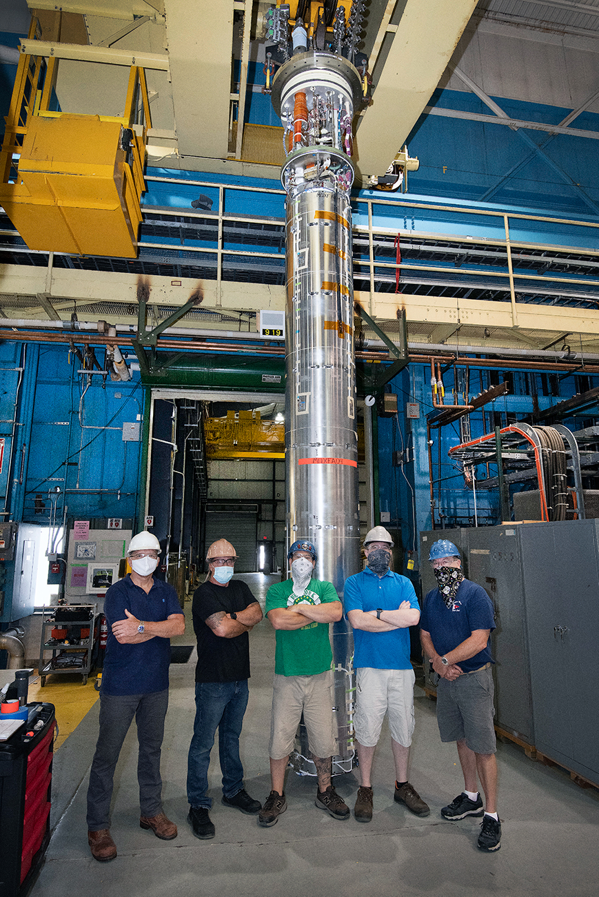
The significant increase in luminosity targeted by the high-luminosity LHC (HL-LHC) demands large-aperture quadrupole magnets that are able to focus the proton beams more tightly as they collide. A total of 24 such magnets are to be installed on either side of the ATLAS and CMS experiments in time for HL-LHC operations in 2027, marking the first time niobium-tin (Nb3Sn) magnet technology is used in an accelerator.
Nb3Sn is a superconducting material with a critical magnetic field that far exceeds that of the niobium-titanium presently used in the LHC magnets, but once formed it becomes brittle and strain-sensitive, which makes it much more challenging to process and use.
The milestone signals the end of the prototyping phase for the HL-LHC quadrupoles
Giorgio Apollinari
Following the first successful test of a US-built HL-LHC quadrupole magnet at Brookhaven National Laboratory (BNL) in January last year—attaining a conductor peak field of 11.4 T and exceeding the required integrated gradient of 556 T in a 150 mm-aperture bore—a second quadrupole magnet has now been tested at BNL at nominal performance. Since the US-built quadrupole magnets must be connected in pairs before they can constitute fully operational accelerator magnets, the milestone signals the end of the prototyping phase for the HL-LHC quadrupoles, explains Giorgio Apollinari of Fermilab, who is head of the US Accelerator Upgrade Projects (AUP). “The primary importance is that we have entered the ‘production’ period that will make installation viable in early 2025. It also means we have satisfied the requirements from our funding agency and now the US Department of Energy has authorised the full construction for the US contribution to HL-LHC.”
Joint venture
The design and production of the HL-LHC quadrupole magnets are the result of a joint venture between CERN, BNL, Fermilab and Lawrence Berkeley National Laboratory, preceded by the 15 year-long US LHC Accelerator Research Program (LARP). The US labs are to provide a total of ten 9 m-long helium-tight vessels (eight for installation and two as spares) for the HL-LHC, each containing two 4.2 m-long magnets. CERN is also producing ten 9 m-long vessels, each containing a 7.5 m-long magnet. The six magnets to be placed on each side of ATLAS and CMS – four from the US and two from CERN – will be powered in series on the same electrical circuit.
The synergy between CERN and the US laboratories allowed us to considerably reduce the risks
Ezio Todesco
“The synergy between CERN and the US laboratories allowed us to considerably reduce the risks, have a faster schedule and a better optimisation of resources,” says Ezio Todesco of CERN’s superconductors and cryostats group. The quadrupole magnet programme at CERN is also making significant progress, he adds, with a short-model quadrupole having recently reached a record 13.4 T peak field in the coil, which is 2 T more than the project requirements. “The full series of magnets, sharing the same design and built on three sites, will also give very relevant information about the viability of future hadron colliders, which are expected to rely on massive, industrial production of Nb3Sn magnets with fields up to 16 T.”
Since the second US quadrupole magnet was tested in October, the AUP teams have completed the assembly of a third magnet and are close to completing the assembly of a fourth. Next, the first two magnets will be assembled in a single cold mass before being tested in a horizontal configuration and then shipped to CERN in time for the “string test” planned in 2023.
“In all activities at the forefront of technology, like in the case for these focusing Nb3Sn quadrupoles, the major challenge is probably the transition from an ‘R&D mentality’, where minor improvements can be a daily business, to a ‘production mentality’, where there is a need to build to specific procedures and criteria, with all deviations being formally treated and corrected or addressed,” says Apollinari. “And let’s not forget that the success of this second magnet test came with a pandemic raging across the world.”
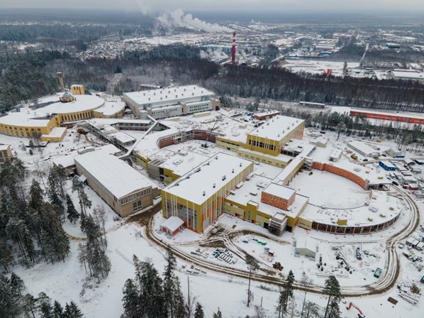
After seven years of construction at the Joint Institute for Nuclear Research (JINR) in Dubna, Russia, the Booster synchrotron at the brand-new NICA (Nuclotron-Based Ion Collider Facility) Complex has accelerated its first beam. On 19 December helium ions were injected into the synchrotron and a stable circulation of the beam was obtained at an energy of 3.2 MeV. The milestone marks an important step in establishing the NICA facility, which is estimated to be completed by 2022.
At this energy, ordinary matter and the quark-gluon plasma coexist in a mixed phase
The NICA accelerator complex will allow studies of the properties of nuclear matter in the region of maximum baryonic density. By colliding heavy gold ions at energies corresponding to the deconfinement phase transition (4.5 GeV), NICA will access the transition of the quark-gluon plasma (QGP) into hadrons. At this energy, ordinary matter and the QGP are able to exist in a so-called mixed phase – complementing studies at higher energy colliders such as the LHC.
The NICA booster is a 211 m circumference superconducting synchrotron which will accelerate beams to 500 MeV. It uses 2.2 m-long dipole and quadrupole magnets made up of a window frame iron yoke and a winding made of a hollow niobium-titanium superconducting cable cooled with a two-phase helium flow. Beams will then be transported to a separate ring surrounding the booster, the “nuclotron”, and accelerated to the GeV range. The nuclotron was originally built between 1987 and 1992 as part of the Dubna “syncrophasotron modernisation” programme, and was Europe’s first superconducting accelerator of heavy ions to high energies. Finally, beams will be injected into two identical 503 m storage rings, which will collide the beams at two detectors: the Multi-Purpose Detector (MPD) and the Spin-Physics Detector (SPD). The MPD facility is designed to study dense baryonic matter, while SPD will study collisions between polarised beams of protons and deuterons.
The complex is one of six Russian “megascience” facilities that are part of the CREMLIN project, which aims to use large-scale science facilities to improve and strengthen relations and networks between European and Russian research infrastructures. The CREMLIN consortium comprises 19 European and Russian research infrastructures, including CERN, and DESY. Other “megascience” facilities included in this project are the Super-Charm-Tau Factory at the Budker Institute of Nuclear Physics, and the Special-purpose Synchrotron-Radiation Source (SSRS-4) at the NRC Kurchatov Institute.
“This is a historical moment for our Laboratory and a great milestone in realization of our flagship megascience project – we have to thank the grant programme CREMLIN helping us in these challenges,” says Vladimir Kekelidze, the NICA project leader. “The final step before the physical launch of the Booster will be the adjustment of the beam acceleration mode, which will then allow focus to switch to the construction of the beam transport systems from the Booster to the Nuclotron.”
To provide the best experiences, we use technologies like cookies to store and/or access device information. Consenting to these technologies will allow us to process data such as browsing behavior or unique IDs on this site. Not consenting or withdrawing consent, may adversely affect certain features and functions.
Functional
Always active
The technical storage or access is strictly necessary for the legitimate purpose of enabling the use of a specific service explicitly requested by the subscriber or user, or for the sole purpose of carrying out the transmission of a communication over an electronic communications network.
Preferences
The technical storage or access is necessary for the legitimate purpose of storing preferences that are not requested by the subscriber or user.
Statistics
The technical storage or access that is used exclusively for statistical purposes.The technical storage or access that is used exclusively for anonymous statistical purposes. Without a subpoena, voluntary compliance on the part of your Internet Service Provider, or additional records from a third party, information stored or retrieved for this purpose alone cannot usually be used to identify you.
Marketing
The technical storage or access is required to create user profiles to send advertising, or to track the user on a website or across several websites for similar marketing purposes.