Multi-bend achromat (MBA) lattices have initiated a fourth generation for storage-ring light sources with orders of magnitude increase in brightness and transverse coherence. A few MBA rings have been built, and many others are in design or construction worldwide, including upgrades of APS and ALS in the US.
The HMBA (hybrid MBA), developed for the successful ESRF–EBS MBA upgrade has proven to be very effective in addressing the nonlinear dynamics challenges associated with pushing the emittance toward the diffraction limit. The evolution of the HMBA ring designs will be described in this seminar. The new designs are consistent with the breaking of the lattice periodicity found in traditional circular light sources, inserting dedicated sections for efficient injection and additional emittance damping.
Techniques developed for high-energy physics rings to mitigate nonlinear dynamics challenges associated with breaking periodicity at collision points were applied in the HMBA designs for the injection and damping sections. These techniques were also used to optimise the individual HMBA cell nonlinear dynamics. The resulting HMBA can deliver the long-sought diffraction limited source while maintaining the temporal and transverse stability of third-generation light sources due to the long lifetime and traditional off-axis injection enabled by nonlinear dynamics optimisation, thus improving upon the performance of rings now under construction.
Pantaleo Raimondi, professor at the Stanford Linear Accelerator Center, research technical manager, SLAC National Accelerator Laboratory and previously director, Accelerator and Source Division, ESRF.
The imminent start of LHC Run 3 following a vast programme of works completed during Long Shutdown 2 marks a milestone for the CERN accelerator complex. When stable proton beams return to the LHC this year (see LHC Run 3: the final countdown), they will collide at higher energies (13.6 compared to 13 TeV) and with higher luminosities (containing up to 1.8 × 10¹¹ protons per bunch compared to 1.3–1.4 × 10¹¹) than in Run 2. Physicists working on the LHC experiments can therefore look forward to a rich harvest of results during the next three years. After Run 3, the statistical gain in running the accelerator without a significant luminosity increase beyond its design and ultimate values will become marginal. Therefore, to maintain scientific progress and to exploit its full capacity, the LHC is undergoing upgrades that will allow a decisive increase of its luminosity during Run 4, expected to begin in 2029, and beyond.
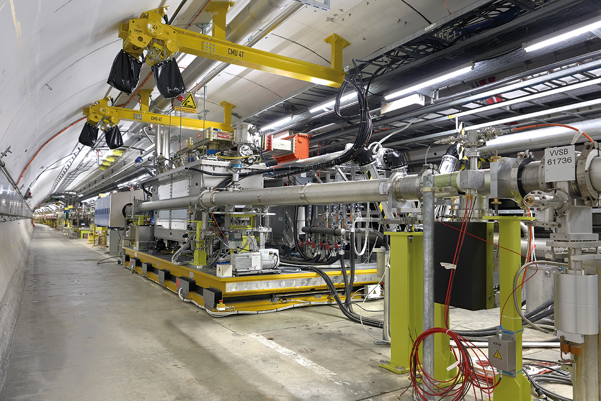
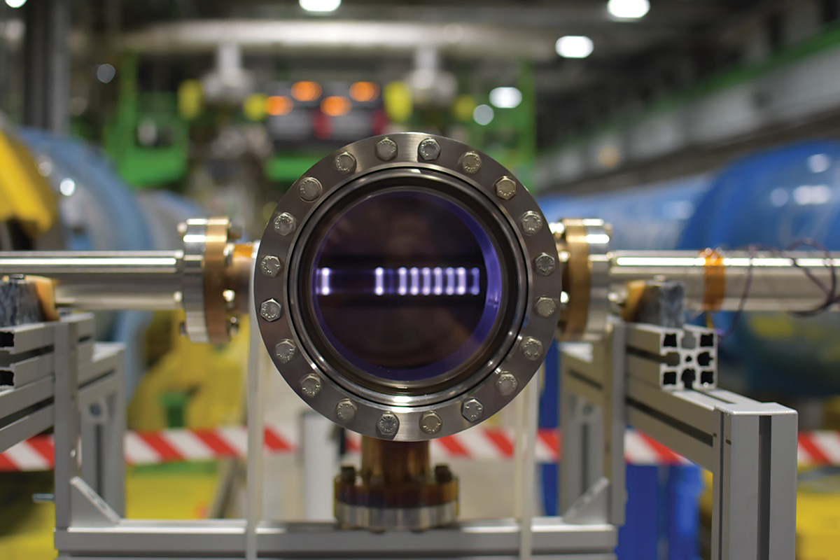
Several technologies are being developed for this High-Luminosity LHC (HL-LHC) upgrade. One is new, large-aperture quadrupole magnets based on a niobium-tin superconductor. These will be installed on either side of the ATLAS and CMS experiments, providing the space required for smaller beam-spot sizes at the interaction points and shielding against the higher radiation levels when operating at increased luminosities. The other key technology, necessary to take advantage of the smaller beam-spot size at the interaction points, is a series of superconducting radio-frequency (RF) “crab” cavities that enlarge the overlap area of the incoming bunches and thus increase the probability of collisions. Never used before at a hadron collider, a total of 16 compact crab cavities will be installed on either side of each of ATLAS and CMS once Run 3 ends and Long Shutdown 3 begins.
At a collider such as the LHC, it is imperative that the two counter-circulating beams are physically separated by an angle, aka the crossing angle, such that bunches collide only in one single location over the common interaction region (where the two beams share the same beam pipe). The bunches at the HL-LHC will be 10 cm long and only 7 μm wide at the collision points, resembling thin long wires. As a result, even a very small angle between the bunches implies an immediate loss in luminosity. With the use of powerful superconducting crab cavities, the tilt of the bunches at the collision point can be precisely controlled to make it optimal for the experiments and fully exploit the scientific potential of the HL-LHC.
Radical concepts
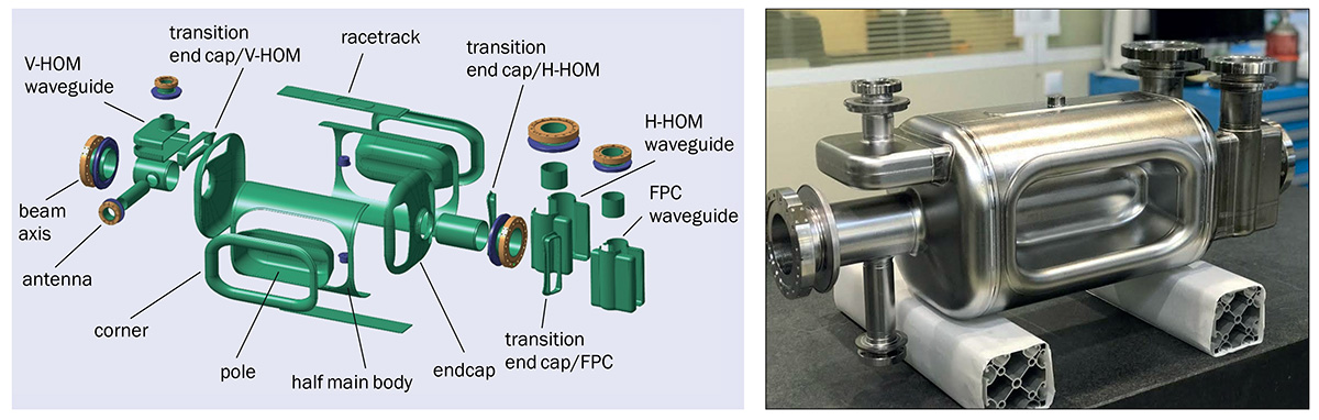
The tight space constraints from the relatively small separation of the two beams outside the common interaction region requires a radically new RF concept for particle deflection, employing a novel shape and significantly smaller cavities than those used in other accelerators. Designs for such devices began around 10 years ago, with CERN settling on two types: double quarter wave (DQW) and RF-dipole (RFD). The former will be fitted around CMS, where bunches are separated vertically, and the latter around ATLAS, where bunches will be separated horizontally, requiring crab cavities uniquely designed for each plane. It is also planned to swap the crossing-angle planes and crab-cavity installations at a later stage during the HL-LHC operation.
In 2017, two prototype DQW-type cavities were built and assembled at CERN into a special cryomodule and tested at 2 K, validating the mechanical, cryogenic and RF functioning. The module was then installed in the Super Proton Synchrotron (SPS) for beam tests, with the world’s first “crabbing” of a proton beam demonstrated on 31 May 2018. In parallel, the fabrication of two prototype RFD-type cavities from high-purity niobium was underway at CERN. Following the integration of the devices into a titanium helium tank at the beginning of 2021, and successful tests at 2 K reaching voltages well beyond the nominal value of 3.4 MV, the cavities were equipped with specially designed RF couplers, which are necessary for beam operations. The two cavities are now being integrated into a cryomodule at Daresbury Laboratory in the UK as a joint effort between CERN and the UK’s Science and Technology Facilities Council (STFC). The cryomodule will be installed in a 15 m-long straight section (LSS6) of the SPS in 2023 for its first test with proton beams. This location in the SPS is equipped with a special by-pass and other services, which were put in place in 2017–2018 to test and operate the DQW-type module.
The manufacturing challenge
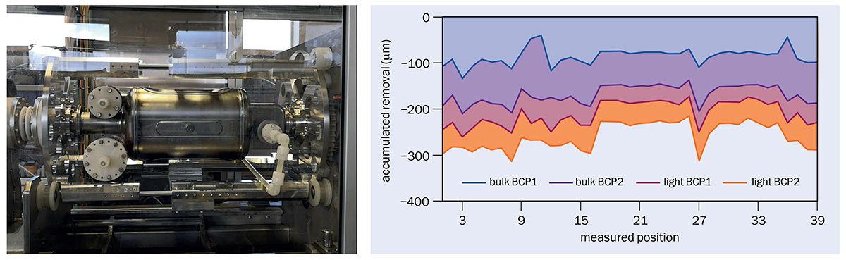
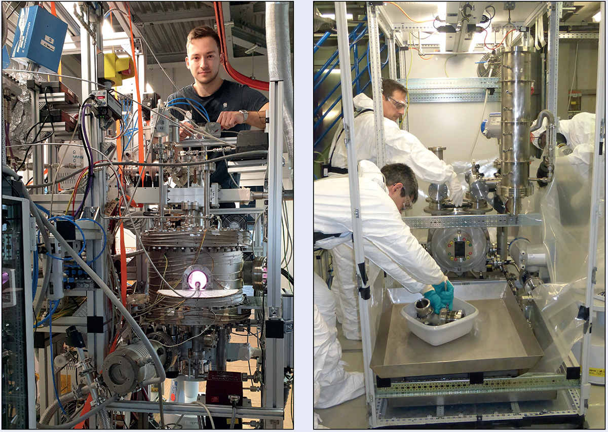
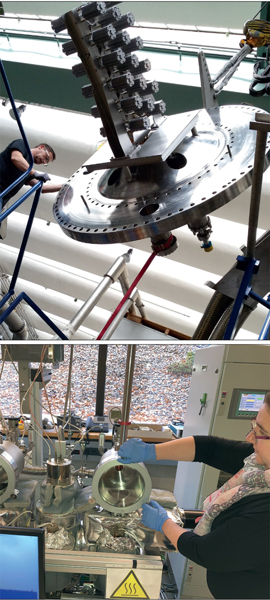
Due to the complex shape and micrometric tolerances required for the HL-LHC crab cavities, a detailed study was performed to realise the final shape through forming, machining, welding and brazing operations on the high-purity niobium sheets and associated materials (see “Fine machining” images). To ensure a uniform removal of material along the cavities’ complex shape, a rotational buffer chemical polishing (BCP) facility was built at CERN for surface etching of the HL-LHC crab cavities. For the RFD and DQW, the rotational setup etches approximately 250 μm of the internal RF surface to remove the damaged cortical layer during the forming process. Ultrasound measurements were performed to follow the evolution of the cavity-wall thickness during the BCP steps, showing remarkable uniformity (see “Chemical etching” images).
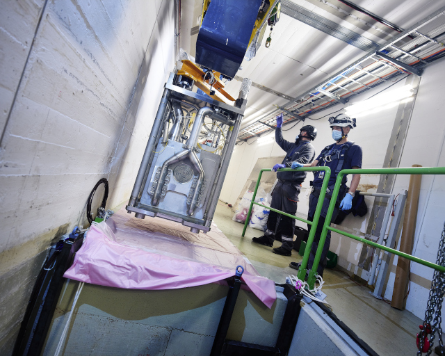
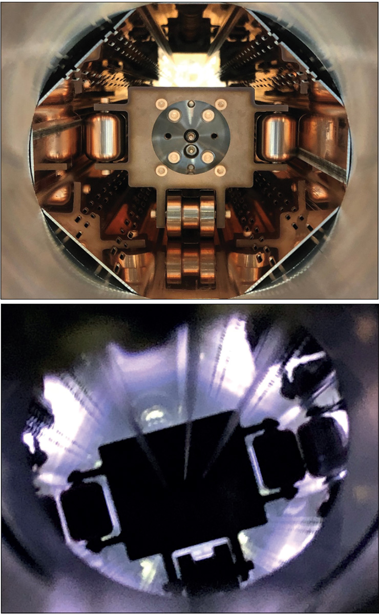
Preparation of the RFD cavities involved a similar process as that for the DQW modules. Following chemical etching and a very high-temperature bake at 650 °C in a vacuum furnace, the cavities are rinsed in ultra-pure water at high pressure (100 bar) for approximately seven hours. This process has proven to be a key step in the HL-LHC crab-cavity preparation to enable extremely high fields and suppress electron-field emitters, which can limit the performance. The cavity is then closed with its RF ancillaries in an ISO4 cleanroom environment to preserve the ultra-clean RF surface, and installed into a special vertical cryostat to cool the cavity surface to its 2 K operating temperature (see “Clean and cool” image, top). Both RFD cavities reached performances well above the nominal target of 3.4 MV. RFD1 reached more than 50% over the nominal voltage and RFD2 reached above a factor of two (7 MV) – a world-record deflecting field in this frequency range. These performances were reproducible after the assembly and welding of the helium tank owing to the careful preparation of the RF surface throughout the different steps of assembly and preparation.
The helium tank provides a volume around the cavity surface that is maintained at 2 K with superfluid helium (see “Clean and cool” image, bottom). Due to sizeable deformations during the cool-down process from ambient temperature, a titanium vessel which has a thermal behaviour close to that of the niobium cavity is used. A magnetic shield between the cavity and the helium tank suppresses stray fields in the operating environment and further preserves cavity performance. Following the tests with helium tanks, the cavities were equipped with higher-order-mode couplers and field antennae to undergo a final test at 2 K before cryostating them into a two-cavity string.
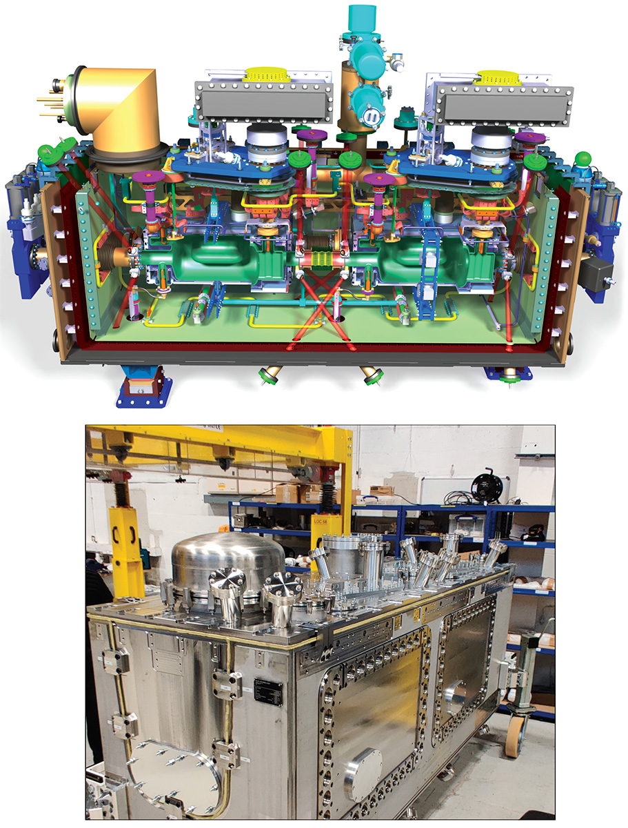
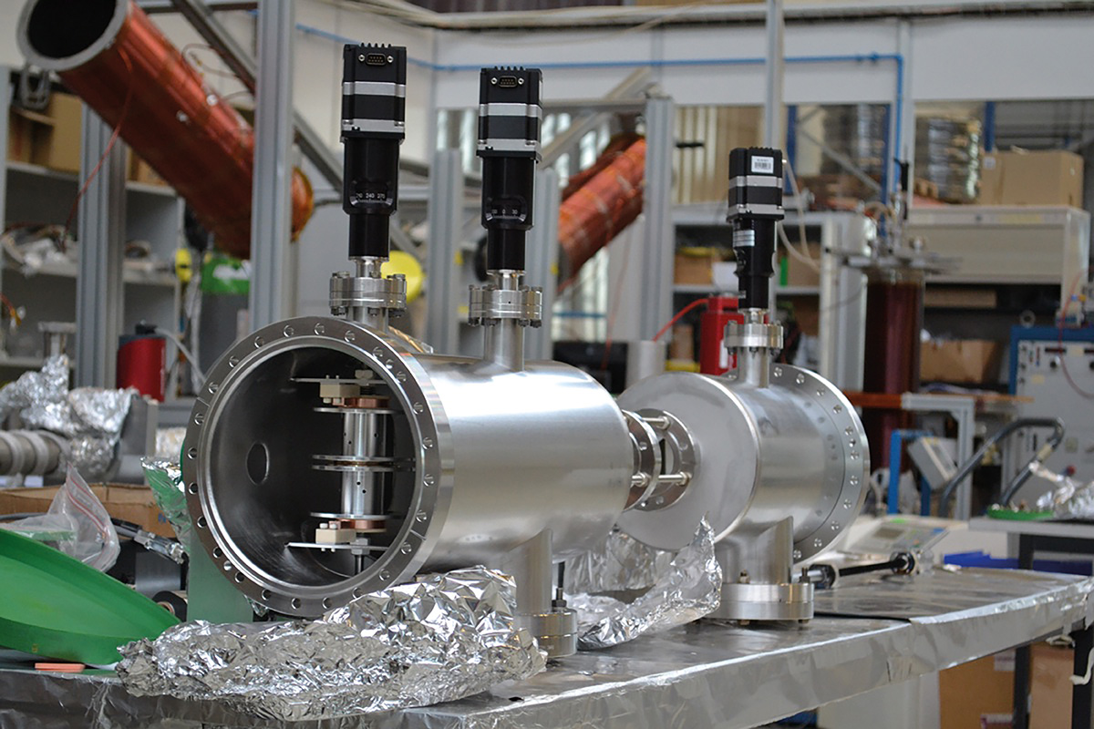
The crab cavities require many ancillary components to allow them to function. This overall system is known as a cryomodule (see “Cryomodule” image, top) and ensures that the operational environment is correct, including the temperature, stability, vacuum conditions and RF frequency of the cavities. Technical challenges arise due to the need to assemble the cavity string in an ISO4 cleanroom, the space constraints of the LHC (leading to the rectangular compact shape), and the requirement of fully welded joints (where typically “O” rings would be used for the insulation vacuum).
Design components
The outer vacuum chamber (OVC) of the cryomodule provides an insulation vacuum to prevent heat leaking to the environment as well as providing interfaces to any external connections. Manufactured by ALCA Technology in Italy, the OVC used a rectangular design where the cavity string is mounted to a top-plate that is lowered into the rest of the OVC, and includes four large windows to allow access for repair in situ if required (see “Cryomodule” image, bottom). Since the first DQW prototype module, several cryomodule interfaces including cryogenic and vacuum components were updated to be fully compatible with the final installation in the HL-LHC.
The HL-LHC crab-cavity programme has developed into a mature project supported by a large number of collaborating institutions around the world
Since superconducting RF cavities can have a higher surface resistance if cooled below their transition temperature in the presence of a magnetic field, they need to be shielded from Earth’s magnetic field and stray fields in the surrounding environment. This is achieved using a warm magnetic shield manufactured in the OVC, and a cold magnetic shield mounted inside the liquid-helium vessel. Both shields, which are made from special nickel-iron alloys, are manufactured by Magnetic Shields Ltd in the UK.
Status and outlook
The RFD crab-cavity pre-series cryomodule will be assembled this year at Daresbury lab, where the infrastructure on site has been upgraded, including an extension to the ISO4 cleanroom area and the introduction of an ISO6 preparation area. A bespoke five-tonne crane has also been installed and commissioned to allow the precise lowering of the delicate cavity string into the outer vacuum vessel.
Parallel activities are taking place elsewhere. The HL-LHC crab-cavity programme has developed into a mature project supported by a large number of collaborating institutions around the world. In the US, the Department of Energy is supporting the HL-LHC Accelerator Upgrade Project to coordinate the efforts and leverage the expertise of a group of US laboratories and universities (FNAL, BNL, JLAB, SLAC, ODU) to deliver the series RFD cavities for the HL-LHC. In 2021, two RFD prototype cavities were built by the US collaboration and exceeded the two most important functional project requirements for crab cavities – deflecting voltage and quality factor. After this successful demonstration, the fabrication of the pre-series cavities was launched.
Crab cavities were first implemented in an accelerator in 2006, at the KEKB electron–positron collider in Japan, where they helped the collider reach record luminosities. A different “crab-waist” scheme is currently employed at KEKB’s successor, SuperKEKB, helping to reach even higher luminosities. The development of ultra-compact, very-high-field cavities for a high-energy hadron collider such as the HL-LHC is even more challenging, and will be essential to maximise the scientific output of this flagship facility beyond the 2030s.
Beyond the HL-LHC, the compact crab-cavity concepts have been adopted by future facilities, including the proton–proton stage of the proposed Future Circular Collider; the Electron–Ion Collider under construction at Brookhaven; bunch compression in synchrotron X-ray sources to produce shorter pulses; and ultrafast particle separators in proton linacs to separate bunches of secondary particles for different experiments. The full implementation of this technology at the HL-LHC is therefore keenly awaited.
The second long-shutdown of the CERN accelerator complex (LS2) is complete. After three years of intense works at all levels across the accelerators and experiments, beams are expected in the LHC in April. For the accelerators, the main LS2 priorities were the consolidation of essential safety elements (dipole diodes) for the LHC magnets, several interventions for the High-Luminosity LHC (HL-LHC) and associated upgrades of the injection chain via the LHC Injectors Upgrade project. Contributing to the achievement of these and many other planned parallel activities, the CERN vacuum team has completed an intense period of work in the tunnels, workshops and laboratories.
Particle beams require extremely low pressure in the pipes in which they travel to ensure that their lifetime is not limited by interactions with residual gas molecules and to minimise backgrounds in the physics detectors. During LS2, all of the LHC’s arcs were vented to the air after warm-up to room temperature and all welds were leak-checked after the diode consolidation (with only one leak found among the 1796 tests performed). The vacuum team also replaced or consolidated around 150 turbomolecular pumps acting on the cryogenic insulation vacuum. In total, 2.4 km of non-evaporable-getter (NEG)-coated beampipes were also opened to the air at room temperature – an exhaustive programme of work spanning mechanical repair and upgrade (across 120 weeks), bake-out (90 weeks) and NEG activation (45 weeks). The vacuum level in these beampipes is now in the required range, with most of the pressure readings below 10–10 mbar.
The vacuum control system was also significantly improved by reducing single points of failure, removing confusing architectures and, for the first time, using mobile vacuum equipment controlled and monitored wirelessly. In view of the higher LHC luminosity and the consequent higher radioactivity dose during Run 3 and beyond, the vacuum group has developed and installed new radiation-tolerant electronics controlling 100 vacuum gauges and valves in the LHC dispersion suppressors. This was the first step of a larger campaign to be implemented in the next long-shutdown, including the production of 1000 similar electronics cards for vacuum monitoring. In parallel, the control software was renewed. This included the introduction of resilient, scalable and self-healing web-based frameworks used by the biggest names in industry.
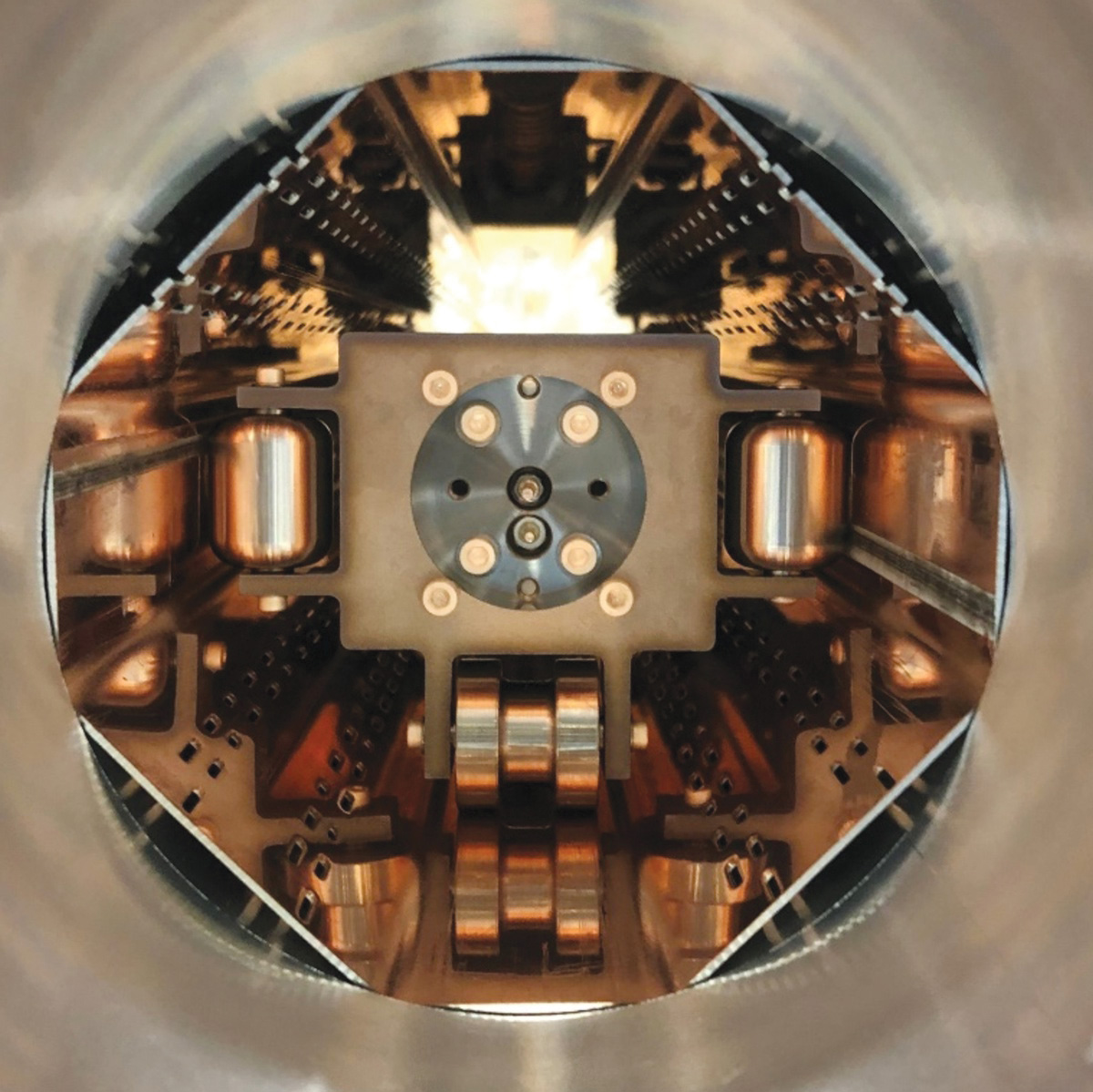
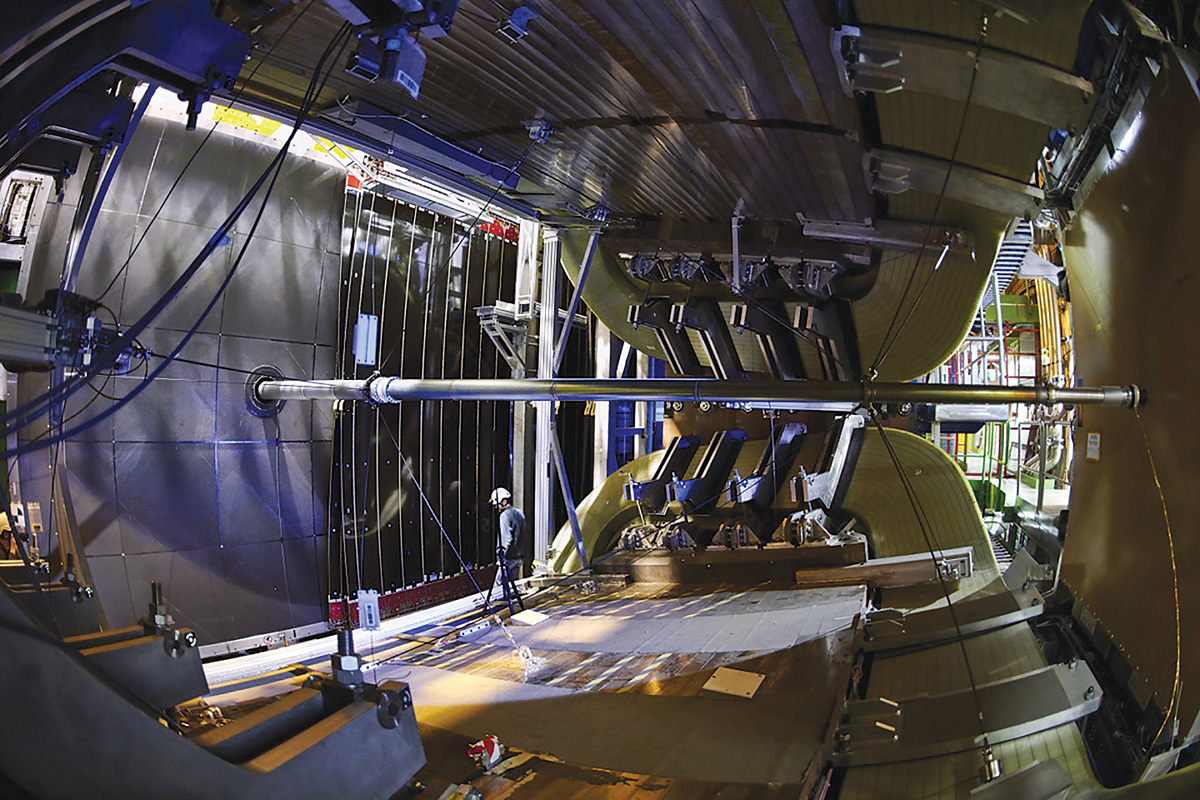
In the LHC experimental areas, the disassembling of the vacuum chambers at the beginning of LS2 required 93 interventions and 550 person-hours of work in the caverns, with the most impressive change in vacuum hardware implemented in CMS and LHCb (see “Interaction points” images). In CMS, a new 7.3 m-long beryllium beam-pipe with an internal diameter of 43.4 mm was installed and 12 new aluminium chambers were manufactured, surface-finished and NEG-coated at CERN. The mechanical installation, including alignments, pump-down and leak detection, took two months, while the bake-out and venting with ultra-pure neon required a further month. In LHCb, the vacuum team contributed to the new Vertex Locator (VELO). Its “RF box” – a delicate piece of equipment filled with silicon detectors, electronics and cooling circuits designed to protect the VELO without affecting the beams – is situated just a few mm from the beam with an aluminium window thinned down to 150 μm by chemical etching and then NEG-coated. As the VELO encloses the RF box and both volumes are under separated vacua, the pump-down is a critical operation because pressure differences across the thin window must be lower than 10 mbar to ensure mechanical integrity. The last planned activity for the vacuum team in LS2, the bake-out of the ATLAS beam pipes, took place in February.
Vacuum challenges
From the list of successful achievements, it could be assumed that vacuum activities in LS2 have gone smoothly, with the team applying well known procedures and practicing knowledge accumulated over decades. However, as might be expected when working with several teams in parallel and at the limits of technology, with around 100 km of piping under vacuum for the LHC alone, this is far from the case. Since the beginning of LS2, CERN vacuum experts have experienced several technical issues and obstacles, a few of which deserve a mention (see “Overcoming the LS2 vacuum obstacles” panel). All these headaches have challenged our regular way of working and allowed us to reflect on procedures, communication and reporting, and technical choices.
But the real moment of truth is still yet to come, when the intensity of the LHC beams reaches the new nominal value boosted by the upgraded injectors. Under the spotlight will be surface electron emission, which drives the formation of electron clouds and their consequences, including beam instabilities and heat load on the cryogenic system. The latter showed anomalously high values during Run 2, with strong inhomogeneity along the ring indicating an uneven surface conditioning. The question is what will happen to the heat load during Run 3? Thanks to the effort and achievements of a dedicated taskforce, the scrubbing and following physics runs will provide a detailed answer in a few months. Last year, the task force installed additional instrumentation in the cryogenic lines in selected positions and, after many months of detective work, identified the most probable culprit of the puzzling heat-load values: the formation of a non-native copper oxide layer during electron bombardment of hydroxylated copper surfaces at cryogenic temperatures. UV exposure in selected gas, local bakeout and plasma etching are among the mitigation techniques we are going to investigate.
The HL-LHC horizon
LS2 might only just have finished but we are already thinking about LS3 (2026–2028), whose leitmotif will be the finalisation of the HL-LHC project. Thanks to more focused beams at the collision points and an increased proton bunch population, the higher beam luminosity at CMS and ATLAS (peaking at a levelled value of 5 × 1034cm–2s–1) will enable an integrated luminosity of 3000 fb–1 in 12 years. For the HL-LHC vacuum systems, this requires a completely new design of the beam screens in the focusing area of the experiments, the implementation of carbon thin-film coatings in the unbaked beampipes to cope with the lower secondary electron yield threshold, and radiation-compatible equipment near the experiments and radiation-tolerant electronics down to the dispersion suppressor zones.
During the first beam-commissioning of the PS, anomalous high proton losses were detected, generating pressure spikes and a high radioactive dose near one of the magnets. An endoscopic inspection (see image above, left) revealed the presence of an orange sponge that had been used to protect the vacuum chamber extremities before welding (and which had been left behind due to a miscommunication between the teams involved), blocking the lower half of the beam pipe. After days of investigation with the beams and interventions by technicians, the chamber was cut open and the offending object removed.
Leaky junctions
Having passed all tests before they were installed, new corrugated thin-walled vacuum chambers installed in the Proton Synchrotron Booster to reduce eddy-current effects suffered vacuum leaks after a few days of magnet pulsing. The leaks appeared in lip-welded junctions in several chambers, indicating a systematic production issue. Additional spare chambers were produced and, as the leaks remain tolerable, a replacement is planned during the next year-end technical stop. Until then, this issue will be the Sword of Damocles on the heads of the vacuum teams in charge of the LHC’s injectors.
Powering mismatch
During the first magnet tests of the TT2 transfer line, a vacuum sector was suddenly air-vented. The support of the vacuum chambers was found to be broken; two bellows were destroyed (see image, middle), and the vacuum chamber twisted. The origin of the problem was a different powering scheme of the magnet embedding the chamber: faster magnetic pulses generated higher eddy-current and Lorentz forces that were incompatible with the beampipe design and supports. It was solved by inserting a thin insulation layer between vacuum flanges to interrupt the eddy current, a practice common in other parts of the injectors.
QRL quirks
The LHC’s helium transfer lines (QRL) require regular checks, especially after warm-up and cool-down. During LS2, the vacuum team installed two additional turbomolecular pumps to compensate for the rate increase of a known leak in sector B12, allowing operation until at least the next long-shutdown. Another troubling leak which opened only for helium pressures above 7 bar was detected in a beam-screen cooling circuit. Fixing it would have required the replacement of the nearby magnet but the leak turned out to be tolerable at cryogenic temperatures, although its on/off behaviour remains to be fully elucidated.
Damaged disks
Installed following the incident in sector 3–4 shortly after LHC startup, the beam vacuum in the LHC arcs is protected against overpressure by 832 “burst disks”. A 30 μm-thick stainless- steel disk membrane nominally breaks when the pressure in the vacuum system is 0.5 bar higher than the tunnel air pressure. Despite the careful venting procedure, 19 disks were either broken or damaged before the re-pumping of the arcs. Subsequent lab tests showed no damage in spare disks cycled 30 times at 1.1 bar. The vacuum teams replaced the damaged disks and are trying to understand the cause.
Buckled fingers
Before cool-down, a 34 mm-diameter ball fitted with a 40 MHz transmitter is pushed through the LHC beam pipes to check for obstacles. The typical defect is a buckling of the RF fingers in the plug-in modules (PIMs) that maintain electrical continuity as the machine thermally contracts. Unfortunately, in two cases the ball arrived damaged, and it took days to collect and identify all the broken pieces. A buckled finger was successfully found in sector 8-1, but another in sector 2-3 (see image, right) was revealed only when the pilot beam circulated. This forced a re-warming of the arc, venting of the beampipe and the replacement of the damaged PIM, followed by additional re-cooling and aperture and electrical tests.
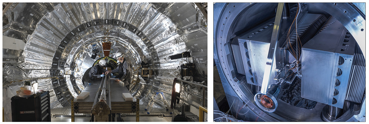
The first piece of vacuum equipment concerned is the “VAX”: a compact set of components, pumps, valves and gauges installed in an area of limited access and relatively high radioactivity between the last focusing magnet of the accelerator and the high-luminosity experiments. The VAX module is designed to be fully compatible with robot intervention, enabling leak detection, gasket change and complete removal of parts to be carried out remotely and safely.
Despite the massive shielding between the experiment caverns and the accelerator tunnels, secondary particles from high-energy proton collisions can reach accelerator components outside the detector area. At nominal HL-LHC luminosity, up to 3.8 kW of power will be deposited in the tunnel on each side of CMS and ATLAS, of which 1.2 kW is intercepted by the 60 m-long sequence of final focusing magnets. Such a power is incompatible with magnet cooling at 1.9 K and, in the long run, could cause the insulation of the superconducting cables to deteriorate. To avoid this issue, the vacuum team designed a new beam screen equipped with tungsten-alloy shielding so that at least half of the power is captured before being transmitted to the magnet cold mass.
All eyes are on the successful restart of the CERN accelerator complex and the beginning of LHC Run 3
The new HL-LHC beam screens took several years of design and manufacturing optimisation, multi-physics simulations and tests with prototypes. The most intense study concerned the mechanical integrity of this complicated object when the hosting magnet undergoes a quench, causing the current to drop from nearly 20 kA to 0 kA in a few tenths of a second. The manufacturing learning phase is now complete and the beam-screen facility will be ready this year, including the new laser-welding robot and cryogenic test benches. Carbon coating is the additional novelty of the HL-LHC beam screens, with the purpose of suppressing electron clouds (see “Beam screen” image). At the beginning of LS2 the first beam screens were successfully coated in situ, involving a small robot carrying carbon and titanium targets, and magnets for plasma confinement during deposition.
The vacuum team is also involved in the production of crab cavities, another breakthrough brought by the HL-LHC project. The surfaces of these complex-shaped niobium objects are treated by a dedicated machine that can provide rotation while chemically polishing with a mixture of nitric, hydrofluoric and phosphoric acids. The vacuum system of the cryomodules in which the cavities are cooled at 2 K was also designed at CERN.
Outlook
Vacuum technology for particle accelerators has been pioneered by CERN since its early days, with the Intersecting Storage Rings bringing the most important breakthroughs. Over the decades, the CERN vacuum group has merged surface-physics specialists, thin-film coating experts and galvanic-treatment professionals, together with teams of designers and colleagues dedicated to the operation of large vacuum equipment. In doing so, CERN has become one of the world’s leading R&D centres for extreme vacuum technology, contributing to major existing and future accelerator projects at CERN and beyond. With the HL-LHC in direct view, the vacuum team looks forward to attacking new challenges. For now, though, all eyes are on the successful restart of the CERN accelerator complex and the beginning of LHC Run 3.
The successful restart of Linac4 on 9 February marked the start of the final countdown to LHC Run 3. Inaugurated in May 2017 after two decades of design and construction, Linac4 was connected to the next link in the accelerator chain, the Proton Synchrotron Booster (PSB), in 2019 at the beginning of Long Shutdown 2 and operated for physics last year. The 86 m-long accelerator now replaces the long-serving Linac2 as the source of all proton beams for CERN experiments.
On 14 February, H– ions accelerated to 160 MeV in Linac4 were sent to the PSB, with beam commissioning and physics to start in ISOLDE on 7 and 28 March. Beams will be sent to the PS on 28 February, to serve, after set-up, experiments in the East Area, the Antiproton Decelerator and n_TOF. The SPS will be commissioned with beam during the week beginning 7 March, after which beams will be supplied to the AWAKE facility and to the North Area experiments, where physics operations are due to begin on 25 April.
Meanwhile, preparations for some of the protons’ final destination, the LHC, are under way. Powering tests and magnet training in the last of the LHC’s eight sectors are scheduled to start in the week of 28 February and to last for four weeks, after which the TI12 and TI18 transfer tunnels and the LHC experiments will be closed and machine checkout will begin. LHC beam commissioning with 450 GeV protons is scheduled to start on 11 April, with collisions at 450 GeV per beam expected around 10 May. Stable beams with collisions at 6.8 TeV per beam and nominal bunch population are scheduled for 15 June. An intensity ramp-up will follow, producing collisions with 1200 bunches per beam in the week beginning 18 July on the way to over double this number of bunches. High-energy proton-proton operations will continue for 3–4 months, before the start of a month-long run with heavy ions on 14 November. All dates are subject to change as the teams grapple with LHC operations at higher luminosities and energies than those during Run 2, following significant upgrade and consolidation work completed during LS2.
Among the highlights of Run 3 are the first runs of the neutrino experiments FASERν and SND@LHC
Among the highlights of Run 3 are the first runs of the neutrino experiments FASERν and SND@LHC, as well as the greater integrated luminosities and physics capabilities resulting from upgrades of the four main LHC experiments. A special request was made by LHCb for a SMOG2 proton-helium run in 2023 to measure the antiproton production rate and thus improve understanding of the cosmic antiproton excess reported by AMS-02. Ion runs with oxygen, including proton-oxygen and oxygen-oxygen, will commence in 2023 or 2024. The former is also long-awaited by the cosmic-ray community, to help improve models of high-energy air showers, while high-energy oxygen-oxygen collisions allow studies of the emergence of collective effects in small systems. High β* runs to maximise the interaction rate will be available for the forward experiments TOTEM and LHCf in late 2022 and early 2023.
On 28 January, CERN announced a change to the LHC schedule to allow necessary work for the High-Luminosity LHC (HL-LHC) both in the machine and in the ATLAS and CMS experiments. The new schedule foresees Long Shutdown 3 to start in 2026, one year later than in the previous schedule, and to last for three instead of 2.5 years. “Although the HL-LHC upgrade is not yet completed, a gradual intensity increase from 1.2 × 10¹¹ to 1.8 × 10¹¹ protons per bunch is foreseen for 2023,” says Rende Steerenberg, head of the operations group. “This promises exciting times and a huge amount of data for the experiments.”
At n_TOF, a 20 GeV/c proton beam from the Proton Synchrotron (PS) strikes an actively cooled pure-lead neutron spallation target. The generated neutrons are water-moderated to produce a spectrum that covers 11 orders of magnitude in energy from GeV down to meV. At the beginning, n_TOF was equipped with a single experimental station, located 185 m downstream from the spallation target. In 2014, a major upgrade saw the construction and operation of a new experimental test area located 20 m above the production target to allow measurements of very low-mass samples. Last year, during Long Shutdown 2, a new third-generation, nitrogen-cooled spallation target was installed and successfully commissioned to prolong the experiment’s lifetime by ten years. At the same time, a new close-to-target irradiation and experimental station called NEAR was added to perform activation measurements relevant nuclear astrophysics and measurements in collaboration with the R2E (Radiation to Electronics) project that are difficult at other facilities.
Advancing technology
During 20 years of activities, the n_TOF collaboration has carried out more than 100 experiments with considerable impact on nuclear astrophysics, advanced nuclear technologies and applied nuclear sciences, including novel medical applications. Understanding the origin of the chemical elements through the slow-neutron-capture process has been a particular highlight. The high instantaneous neutron flux, which is only available at n_TOF thanks to the short proton pulse delivered by the PS, provided key reaction rates relevant to big-bang nucleosynthesis and stellar evolution (the former attempting to explain the discrepancy between the predicted and existing amount of lithium by investigating 7Be creation and destruction, and the latter determining the chemical history of our galaxy).
Basic nuclear data are also essential for the development of nuclear-energy technology. It was this consideration that motivated Rubbia to propose a spallation neutron source at CERN in the first place, prompting a series of accurate neutron cross-section measurements on minor actinides and fission products. Neutron reaction processes on thorium, neptunium, americium, curium, in addition to minor isotopes of uranium and plutonium, have been all measured at n_TOF. These measurements provide the nuclear data necessary for the development of advanced nuclear systems, such as the increase of safety margins in existing nuclear plants as well as to enable generation-IV reactors and accelerator-driven systems, or even enabling new fuel cycles which reduce the amount of long-lived nuclear species.
Basic nuclear data are also essential for the development of nuclear-energy technology
Contributions from external laboratories, such as J-PARC (Japan), the Chinese Spallation Neutron Source (China), SARAF (Israel), GELINA (Belgium), GANIL (France) and Los Alamos (US), highlighted synergies in the measurement of neutron-induced capture, fission and light-charged-particle reactions for nuclear astrophysics, advanced nuclear technologies, and medical applications. Moreover, technologies developed at CERN have also influenced the creation of two startups, Transmutex and Newcleo. The former focuses on accelerator-driven systems for energy production, for which the first physics validation was executed at the FEAT and TARC experiments at the CERN PS in 1999, while the latter plans to develop critical reactors based on liquid lead.
With the recent technical upgrades and the exciting physics programme in different fields, such as experiments focusing on the breaking of isospin symmetry in neutron-neutron scattering and pursuing its core experimental activities, the n_TOF facility has a bright future ahead.
The ALICE detector has undergone significant overhauls during Long Shutdown 2 to prepare for the higher luminosities expected during Run 3 and 4 of the LHC, starting this year. Further upgrades of the inner tracking system and the addition of a new forward calorimeter are being planned for the next long shutdown, ahead of Run 4. A series of physics questions will still remain inaccessible with Run 3 and 4, and major improvements in the detector performance and an ability to collect an even greater integrated luminosity are needed to address them in Run 5 and beyond. The ideas for a heavy-ion programme for Run 5 and 6 are part of the European strategy for particle physics. At the beginning of 2020, the ALICE collaboration formed dedicated working groups to work out the physics case, the physics performance, and a detector concept for a next-generation heavy-ion experiment called “ALICE 3”.
To advance the project further, the ALICE collaboration organised a hybrid workshop on October 18 and 19, attracting more than 300 participants. Invited speakers on theory and experimental topics reviewed relevant physics questions for the 2030s, and members of the ALICE collaboration presented detector plans and physics performance studies for ALICE 3. Two key areas are the understanding how thermal equilibrium is approached in the quark-gluon plasma (QGP) and the precise measurement of its temperature evolution.
Restoring chiral symmetry
Heavy charm and beauty quarks are ideal probes to understand how thermal equilibrium is approached in the QGP, since they are produced early in the collision and are traceable throughout the evolution of the system. Measurements of azimuthal distributions of charm and beauty hadrons, as well as charm-hadron pairs, are particularly sensitive to the interactions between heavy quarks and the QGP. In heavy-ion collisions, heavy charm quarks are abundantly produced and can hadronise into rare multi-charm baryons. The production yield of such particles is expected to be strongly enhanced compared to proton-proton collisions because the free propagation of charm quarks in the deconfined plasma allows the combination of quarks from different initial scatterings.
Electromagnetic radiation is a powerful probe of the temperature evolution of the QGP. Since real and virtual photons emitted throughout the evolution of the system are not affected by the strong interaction, differential measurements of dielectron pairs produced from virtual photons allow physicists to determine the temperature evolution in the plasma phase. Given the high temperature and density of the quark-gluon plasma, chiral symmetry is expected to be restored. ALICE 3 will allow us to study the mechanisms of chiral symmetry restoration from the imprint on the dielectron spectrum.
New specialised detectors are being considered to further extend the physics reach
To achieve the performance required for these measurements and the broader proposed ALICE 3 physics programme, a novel detector concept has been envisioned. At its core is a tracker based on silicon pixel sensors, covering a large pseudo-rapidity range and installed within a new superconducting magnet system. To achieve the ultimate pointing resolution, a retractable high-resolution vertex detector is to be placed in the beampipe. The tracking is complemented by particle identification over the full acceptance, realised with different technologies, including silicon-based time-of-flight sensors. Further specialised detectors are being considered to further extend the physics reach.
ALICE 3 will exploit completely new detector components to significantly extend the detector capabilities and to fully exploit the physics potential of the LHC. The October workshop marked the start of the discussion of ALICE 3 with the community at large and of the review process with the LHC experiments committee.
Within a particle accelerator, the surface of materials directly exposed to the beams interacts with the circulating particles and, in so doing, influences the local vacuum conditions through which those particles travel. Put simply: accelerator performance is linked inextricably to the surface characteristics of the vacuum beam pipes and chambers that make up the machine.
In this way, the vacuum vessel’s material top surface and subsurface layer (just a few tens of nm thick) determine, among many other characteristics, the electrical resistance of the beam image current, synchrotron light reflectivity, degassing rates and secondary electron yield under particle bombardment. The challenge for equipment designers and engineers is that while the most common structural materials used to fabricate vacuum systems – stainless steel, aluminium alloys and copper – ensure mechanical resistance against atmospheric pressure, they do not deliver the full range of chemical and physical properties required to achieve the desired beam performance.
Sputtering is one of the methods used to produce thin films by physical vapour deposition
Aluminium alloys, though excellent in terms of electrical conductivity, suffer from high secondary electron emission. On the latter metric, copper represents a better choice, but can be inadequate regarding gas desorption and mechanical performance. Even though it is the workhorse of vacuum technology, for its excellent mechanical and metallurgical behaviour, stainless steel lacks most of the required surface properties. The answer is clear: adapt the surface properties of these structural materials to the specific needs of the accelerator environment by coating them with more suitable materials, typically using electrochemical or plasma treatments. (For a review of electrochemical coating methods, see Surface treatment: secrets of success in vacuum science.)
Variations on the plasma theme
The emphasis herein is exclusively on plasma-based thin-film deposition, in which an electrically quasi-neutral state of matter (composed of positive and negative charged particles) is put to work to re-engineer the physical and chemical properties of vacuum component/subsystem surfaces. A plasma can be produced by ionising gas atoms so that the positive charges are ions, and the negative ones are electrons. The most useful properties of the resultant gas plasma derive from the large difference in inertial mass between the particles carrying negative and positive charges. Owing to their much lower inertial mass, electrons are a lot more responsive than ions to variations of the electromagnetic field, leading to separation of charges and electrical fields within the plasma. What’s more, the particle trajectories for ions and electrons also differ markedly.
These characteristics can be exploited to deposit thin films and, more generally, to modify the properties of vacuum chamber and component surfaces. For such a purpose, noble-gas ions are extracted from a plasma and accelerated towards a negatively charged solid target. If the ions acquire enough kinetic energy (of the order of hundreds to thousands of eV), one of the effects of the bombardment is the extraction of neutral atoms from the target and their deposition on the surface of the substrate to be modified. This mechanism – called sputtering – is one of the methods used to produce thin films by physical vapour deposition (PVD), where film materials are extracted from a solid into a gas phase before condensing on a substrate.
In the plasma, the lost ions are reintroduced by electron ionisation of additional gas atoms. While the rate of ionisation is improved by increasing the gas density, an excessive gas density can have a detrimental effect on the sputtered atoms (as their trajectories are modified and their kinetic energy decreased by multiple collisions with gas atoms). The alternative is to increase the length of the electron trajectories by applying a magnetic field of several hundred gauss to the plasma.
Contrary to ions – which are affected minimally – electrons move around the lines of force of the magnetic field in longer helical-like curves, such that the probability of hitting an atom is higher. As electrons are sooner or later lost – either on the growing film or nearby surfaces – the plasma is refilled by secondary electrons extracted from the target (as a result of ion collisions). For a given set of parameters – among them target voltage, plasma power, gas pressure and magnetic flux density – the plasma ultimately attains stable conditions and a constant rate of deposition. Typical film thicknesses for accelerator applications range from a few tens of nm to 2–3 microns.
Unique requirements
The peculiarities of thin-film deposition for accelerator applications lie in the size of the objects to be coated and the purity of the coatings in question. Substrate areas, for example, range from a few cm2 up to m2, and in a great variety of 3D shapes and geometries. Large-aspect-ratio beam pipes that are several metres long or complicated multicell cavities for RF applications are typical substrates regularly coated at CERN. The coating process is implemented either in dedicated workshops or directly inside the accelerators during the retrofitting of installed equipment.
HiPIMS target geometriesand coating parametersmust beoptimised for each family of acceleratorcomponents
The simplest sputtering configuration can be deployed when coating a cylindrical beam pipe. The target, which is made of a wire or a rod of the material to be deposited, is aligned along the longitudinal axis of the beam pipe. Argon is the most commonly used noble gas, at a pressure that depends on the cross-section – i.e. the smaller the diameter, the higher the pressure (a typical value for vacuum chambers that are a few centimetres in diameter is 0.1 mbar). The plasma is ignited by polarising the target negatively (at a few hundred volts) using a DC power supply while keeping the pipe grounded. It’s possible to reduce the pressure by one or two orders of magnitude if a magnetic field is applied parallel to the target (owing to the longer electron paths). In this case, the deposition technique is known as DC magnetron sputtering.
When the substrate is not a simple cylinder, however, the target design becomes more complicated. That’s because of the need to accommodate different target–substrate distances, while the angle of incidence of sputtered atoms on the substrate is also subject to change. As a result, the deposited film might have different thicknesses and uneven properties at different locations on the substrate (owing to dissimilar morphologies, densities and defects, including voids). These weaknesses have been addressed, in large part, over recent years with a new family of sputtering methods called high-power impulse magnetron sputtering (HiPIMS).
In HiPIMS, short plasma pulses (of the order of 10-100 μs) of high power density (kW/cm2 regime) are applied to the target. The discharge is shut down between two consecutive pulses for a duration of about 100–1000 μs; in this way, the duty cycle is low (less than 10%) and the average power ensures there is no overheating and deformation of the target. The resulting plasma, though, is about 10 times denser (approximately 1013 ions/cm3) versus standard DC magnetron sputtering – a figure of merit that, thanks to a bias voltage applied to the substrate, ensures a higher fraction of ionised sputtered atoms are transported to the surfaces to be coated.
The impingement of such energetic ions produces denser films and reduces the columnar structure resulting from the deposition of sputtered atoms moving along lines of sight. As the bias voltage is not always a safe and practical solution, the CERN vacuum team has successfully tested the application of a positive pulse to the target immediately after the main negative pulse. The effect is an increase in energy of the ionised sputtered atoms, with equivalent results as per the bias voltage (though with a simpler implementation for accelerator components).
Owing to the variety of materials and shapes encountered along a typical (or atypical) beamline, the HiPIMS target geometries and coating parameters must be optimised for each distinct family of accelerator components. This optimisation phase is traditionally experimental, based on testing and measurement of “coupon samples” and then prototypes. In the last five years, however, the CERN team has reinforced these experimental studies with 3D simulations based on a particle-in-cell Monte Carlo/direct simulation Monte Carlo (PICMS/DSMC) code – a capability originally developed at the Fraunhofer Institute for Surface Engineering and Thin Films (IST) in Braunschweig, Germany.
Surface cleaning: putting plasmas to work
Notwithstanding their central role in thin-film deposition, plasmas are also used at CERN to clean surfaces for vacuum applications and to enhance the adherence of thin films. A case in point is the application of plasmas containing oxygen ions and free radicals (highly reactive chemical species) for the removal of hydrocarbons. In short: the ions and radicals are driven toward the contaminated surface, where they can decompose hydrocarbon molecules and form volatile species (e.g. CO and CO2) for subsequent evacuation.
It’s a method regularly used to clean beryllium surfaces (which cannot be treated by traditional chemical methods for safety reasons). If the impingement kinetic energy of the oxygen ions is about 100 eV, the chemical reaction rate on the surface is much larger than the beryllium sputtering rate, such that cleaning is possible without producing hazardous compounds of the carcinogenic metal.
Meanwhile, plasma treatments have recently been proposed for the cleaning of stainless-steel radioactive components when they are dismounted from accelerators, modified and then reinstalled. Using a remote plasma source, the energy of the plasma’s oxygen ions is chosen (<50 eV) so as to avoid sputtering of the component materials, thereby preventing radioactive atoms from entering the gas phase. The main difficulty here is to adapt the plasma source to the wealth of different geometries that are typical of accelerator components.
Plasma versatility
So much for the fundamentals of plasma processing, what of the applications? At CERN, the large-scale deployment of thin-film coatings began in the 1980s on the Large Electron–Positron (LEP) collider. To increase LEP’s collision energy to 200 GeV and above, engineering teams studied, and subsequently implemented, superconducting niobium (Nb) thin films deposited on copper (Cu) for the RF cavities (in place of bulk niobium).
This technology was also adopted for the Large Hadron Collider (LHC), the High Intensity and Energy ISOLDE (HIE ISOLDE) project at CERN and other European accelerators operating at fields up to 15 MV/m. The advantages are clear: lower cost, better thermal stability (thanks to the higher thermal conductivity of the copper substrate), and reduced sensitivity to trapped magnetic fields. The main drawback of Nb/Cu superconducting RF cavities is an exponential growth of the power lost in an RF cycle with the accelerating electrical field (owing to resistivity and magnetic permeability of the Nb film). This weakness, although investigated extensively, has eluded explanation and proposed mitigation for the past 20 years.
NEG coatings comprise a mixture of titanium, zirconium and vanadium
It’s only lately, in the frame of studies for the proposed electron–positron Future Circular Collider (FCC-ee), that researchers have shed light on this puzzling behaviour. Those insights are due, in large part, to a deeper theoretical analysis of Nb thin-film densification as a result of HiPIMS, though a parallel line of investigation involves the manufacturing of seamless copper cavities and their surface electropolishing. In both cases, the objective is the reduction of defects in the substrate to enhance film adherence and purity.
Related studies have shown that Nb films on Cu can perform as well as bulk Nb in terms of superconducting RF properties, though coating materials other than Nb are also under investigation. Today, for example, the CERN vacuum group is evaluating Nb3Sn and V3Si – both of which are part of the A15 crystallographic group and exhibit superconducting transition temperatures of about 18 K (i.e. 9 K higher than Nb). This higher critical temperature would allow the use of RF cavities operating at 4.3 K (instead of 1.9 K), yielding significant simplification of the cryogenic infrastructure and reductions in electrical energy consumption. Even so, intense development is still necessary before these coatings can really challenge pure Nb films – not least because A15 films are brittle, plus the coating of such materials is tricky (given the need to reproduce a precise stoichiometry and crystallographic structure).
Game-changing innovations
Another wide-scale application of plasma processing at CERN is in the deposition of non-evaporable-getter (NEG) thin-film coatings, specialist materials originally developed to provide distributed vacuum pumping for the LHC. NEG coatings comprise a mixture of titanium, zirconium and vanadium with a typical composition around 30:30:40, respectively. For plasma deposition of NEG films, the target (comprising three interlacing elemental wires) is pulled along the main axis of the beam pipes. Once the coated vacuum chambers are installed within an accelerator and pumped out, the NEG films undergo heating for 24 hours at temperatures ranging from 180 to 250 °C – a process known as activation, in which the superficial oxide layer and any contaminants are dissolved into their bulk.
The clean surfaces obtained in this way chemically adsorb most of the gas species in the vacuum system at room temperature – except for noble gases (which are chemically inert) and methane (for which small auxiliary pumps are necessary). The NEG-coated surfaces provide an impressively high pumping speed and, thanks to their cleanliness, a lower desorption yield when bombarded by electrons, photons and ions – and all this with minimal space occupancy. Moreover, owing to their maximum secondary electron yields (δmax) below 1.3, NEG coatings avoid the development of electron multipacting, the main cause of electron clouds in beam pipes (and related unfavourable impacts on beam performance, equipment operation and cryogenic heat load).
More broadly, plasma processing of NEG coatings represents a transformative innovation in the implementation of large-scale vacuum systems. Hundreds of beam pipes were NEG-coated for the long straight section of the LHC, including the experimental vacuum chambers inserted in the four gigantic detectors. Beyond CERN, NEG coatings have also been employed widely in other large scientific instruments, including the latest generation of synchrotron light sources.
Of course, NEG coatings require thermal activation, so cannot be applied in vacuum systems that are unheatable (i.e. vacuum vessels that operate at cryogenic temperatures or legacy accelerators that may need retrofitting). For these specific cases, the CERN vacuum team has, over the past 15 years, been developing and iterating low-δmax carbon coatings comprised mostly of amorphous carbon (a-C) with prevailing graphitic-like bonding among the carbon atoms.
Even though a-C thin films were originally studied for CERN’s older Super Proton Synchrotron (SPS), they are now the baseline solution for the beam screen of the superconducting magnets in the long straight section of the High-Luminosity LHC. A 100 nm thin coating is deposited either in the laboratory for the new magnets (located on both sides of the ATLAS and CMS detectors) or in situ for the ones already installed in the tunnel (both sides of LHCb and ALICE).
Production of denser plasmas will be key for future applications in surface treatments for accelerators
The in situ processing has opened up another productive line of enquiry: the possibility of treating the surface of beam screens (15 m long, a few cm diameter) directly in the accelerators with the help of mobile targets. The expectation is that these innovative coating methods for a-C could, over time, also be applied to improve the performance of installed vacuum chambers in the LHC’s arcs, without the need to dismount magnets and cryogenic connections.
Opportunity knocks
Looking ahead, the CERN vacuum team has plenty of ideas regarding further diversification of plasma surface treatments – though the direction of travel will ultimately depend on the needs of future studies, projects and collaborations. Near term, for example, there are possible synergies with the Advanced Proton Driven Plasma Wakefield Acceleration Experiment (AWAKE), an accelerator R&D project based at CERN that’s investigating the use of plasma wakefields driven by a proton bunch to accelerate charged particles over short distances. Certainly, the production of denser plasmas (and their manipulation) will be key for future applications in surface treatments for accelerators.
Another area of interest is the use of plasma-assisted chemical vapour deposition to extend the family of materials that can be deposited. For the longer term, the coating of vacuum systems with inert materials that allow the attainment of very low pressures (in the ultrahigh vacuum regime) in a short timeframe (five years) without bakeout remains one of the most ambitious targets.
The reliability of the CERN vacuum systems is very much front-and-centre as the restart of the LHC physics programme approaches in mid-2022. The near-term priority is the recommencement of beam circulation in vacuum systems that were open to the air for planned interventions and modification – sometimes for several days or weeks – during Long Shutdown 2 (LS2), a wide-ranging overhaul of CERN’s experimental infrastructure that’s been underway since the beginning of 2019.
With LS2 now drawing to a close and pilot beam already circulated in October for a general check of the accelerator chain, it’s worth revisiting the three operational objectives that CERN’s engineering teams set out to achieve during shutdown: consolidation of the LHC dipole diodes (essential safety elements for the superconducting magnets); the anticipation of several interventions required for the High-Luminosity LHC (HL–LHC) project (the successor to the LHC, which will enter operation in 2028); and the LHC Injectors Upgrade project to enhance the injection chain so that beams compatible with HL–LHC expectations can be injected into CERN’s largest machine.
“The CERN vacuum team has made fundamental contributions to the achievement of the LS2 core objectives and other parallel activities,” notes Paolo Chiggiato, head of the CERN vacuum, surfaces and coatings group. “As such, we have just completed an intense period of work in the accelerator tunnels and our laboratories, as well as running and supporting numerous technical workshops.”
As for vacuum specifics, all of the LHC’s arcs were vented to the air after warm-up to room temperature; all welds were leak-checked after the diode consolidation (with only one leak found among the 1796 tests performed); while the vacuum team also replaced or consolidated around 150 turbomolecular pumps acting on the cryogenic insulation vacuum. In total, 2.4 km of non-evaporable-getter (NEG)-coated beampipes were also opened to the air at room temperature – an exhaustive programme of work spanning mechanical repair and upgrade (across 120 weeks), bakeout (spread across 90 weeks) and NEG activation (over 45 weeks). “The vacuum level in these beampipes is now in the required range, with most of the pressure readings below 10–10 mbar,” explains Chiggiato.
Close control
Another LS2 priority for Chiggiato and colleagues involved upgrades to CERN’s vacuum control infrastructure, with the emphasis on reducing single points of failure and the removal of confusing architectures (i.e. systems with no clear separation of function amongst the different programmable logic controllers). “For the first time,” adds Chiggiato, “mobile vacuum equipment was controlled and monitored by wireless technologies – a promising communication choice for distributed systems and areas of the accelerator complex requiring limited stay.”
Elsewhere, in view of the higher LHC luminosity (and consequent increased radioactivity) following LS2 works, the vacuum group developed and installed advanced radiation-tolerant electronics to control 100 vacuum gauges and valves in the LHC dispersion suppressors. This roll-out represents the first step of a longer-term campaign that will be scaled during the next Long Shutdown (LS3 is scheduled for 2025–2027), including the production of 1000 similar electronic cards for vacuum monitoring. “In parallel,” says Chiggiato, “we have renewed the vacuum control software – introducing resilient, easily scalable and self-healing web services technologies and frameworks used by some of the biggest names in industry.”
Success breeds success
In the LHC experimental area, meanwhile, the disassembly of the vacuum chambers at the beginning of LS2 required 93 interventions and 550 person-hours of work in the equipment caverns. Reinstallation has progressed well in the four core LHC experiments, with the most impressive refit of vacuum hardware in the CMS and LHCb detectors.
For the former, the vacuum team installed a new central beryllium chamber (internal diameter 43.4 mm, 7.3 m long), while 12 new aluminium chambers were manufactured, surface-finished and NEG-coated at CERN. Their production comprised eight separate quality checks, from surface treatment to performance assessment of the NEG coating. “The mechanical installation – including alignments, pump-down and leak detection – lasted two months,” explains Chiggiato, “while the bake-out equipment installation, bake-out process, post-bake-out tests and venting with ultrapure neon required another month.”
Thankfully, creative problem-solving is part of the vacuum team’s DNA
In LHCb, the team contributed to the new version of the Vertex Locator (VELO) sub-detector. The VELO’s job is to pick out B mesons from the multitude of other particles produced – a tricky task as their short lives will be spent close to the beam. To find them, the VELO’s RF box – a delicate piece of equipment filled with silicon detectors, electronics and cooling circuits – must be positioned perilously close to the point where protons collide. In this way, the sub-detector faces the beam at a distance of just 5 mm, with an aluminium window thinned down to 150 μm by chemical etching prior to the deposition of a NEG coating.
As the VELO encloses the RF box, and both volumes are under separate vacuum, the pumpdown is a critical operation because pressure differences across the thin window must be lower than 10 mbar to ensure mechanical integrity. “This work is now complete,” says Chiggiato, “and vacuum control of the VELO is in the hands of the CERN vacuum team after a successful handover from specialists at Nikhef [the Dutch National Institute for Subatomic Physics].”
Wrapping up a three-year effort, the vacuum team’s last planned activity in LS2 involves the bake-out of the ATLAS and CMS beampipe in early 2022. “There was no shortage of technical blockers and potential show-stoppers during our LS2 work programme,” Chiggiato concludes. “Thankfully, creative problem-solving is part of the vacuum team’s DNA, as is the rigorous application of vacuum best practice and domain knowledge accumulated over decades of activity. Ours is a collective mindset, moreover, driven by a humble approach to such complex technological installations, where every single detail can have important consequences.”
A detailed report on the CERN vacuum team’s LS2 work programme – including the operational and technical challenges along the way – will follow in the March/April 2022 issue of CERN Courier magazine.
Christian Day is a vacuum scientist on a mission – almost evangelically so. As head of the Vacuum Lab at Karlsruhe Institute of Technology (KIT), part of Germany’s renowned network of federally funded Helmholtz Research Centres, Day and his multidisciplinary R&D team are putting their vacuum know-how to work in tackling some of society’s “grand challenges”.
Thinking big goes with the territory. As such, the KIT Vacuum Lab addresses a broad-scope canvas, one that acknowledges the core enabling role of vacuum technology in all manner of big-science endeavours – from the ITER nuclear-fusion research programme to fundamental studies of the origins of the universe (Day is also technical lead for cryogenic vacuum on the design study for the Einstein Telescope, a proposed next-generation gravitational-wave observatory).
Here, Day tells CERN Courier about the Vacuum Lab’s unique R&D capabilities and the importance of an integrated approach to vacuum system development in which modelling, simulation and experimental validation all work in tandem to foster process and technology innovation.
What are the long-term priorities of the KIT Vacuum Lab?
Our aim is to advance vacuum science and technology along three main pathways: an extensive R&D programme in collaboration with a range of university and scientific partners; design and consultancy services for industry; and vacuum education to support undergraduate and postgraduate science and engineering students at KIT. It’s very much a multidisciplinary effort, with a staff team of 20 vacuum specialists working across physics, software development and the core engineering disciplines (chemical, mechanical, electrical). They’re supported, at any given time, by a cohort of typically five PhD students.
So what does that mean in terms of the team’s core competencies?
At a headline level, we’re focused around the two fundamental challenges in modern vacuum science: the realisation of a physically consistent description of outgassing behaviours for a range of materials and vacuum regimes; also the development of advanced vacuum gas dynamics methods and associated supercomputer algorithms.
As such, one of the main strengths of the KIT Vacuum Lab is our prioritisation of predictive code development alongside experimental validation – twin capabilities that enable us to take on the design, delivery and project-management of the most complex vacuum systems. The resulting work programme is nothing if not diverse – from very-large-scale vacuum pumping systems for nuclear fusion to contamination-free vacuum applications in advanced manufacturing (e.g. extreme UV lithography and solar-cell fabrication).
What sets the KIT Vacuum Lab apart from other vacuum R&D programmes?
Over the last 10 years or so, and very much driven by our contribution to the ITER nuclear fusion project in southern France, we have developed a unique and powerful software capability to model vacuum regimes at a granular level – from atmospheric pressure all the way down to extreme-high-vacuum (XHV) conditions (10–10 Pa and lower). This capability, and the massive computational resources that make it possible, are being put to use across all manner of advanced vacuum applications – quantum computing, HyperLoop transportation systems and gravitational-wave experiments, among others.
Mistakenly, early-career researchers often think that vacuum is a somehow old-fashioned service that they can buy off-the-shelf
The Vacuum Lab’s organising principles are built around “integrated process development”. What does that look like operationally?
It means we take a holistic view regarding the development of vacuum processes, which allows us to identify the main influences in the vacuum system and to map them theoretically or experimentally. An iterative design evolution must not only be based on efficient models; it must also be validated and parameterised by using experimental data from different levels of the process hierarchy. Experimental data are indispensable to evaluate the pros and cons of competing models and to quantify the uncertainties of model predictions.
In turn, the department’s research structure is set up to address elementary processes and unit functions within a vacuum system. When choosing a vacuum pump, for example, it’s important to understand how the pump design, underlying technology and connectivity will influence other parts of the vacuum system. It’s also necessary, though too often forgotten, for the end-user to understand the ultimate purpose of the vacuum system – the why – so that they can address any issues arising in terms of the vacuum science fundamentals and underlying physics.
What are your key areas of emphasis in fusion research right now?
Our vacuum R&D programme in nuclear fusion is carried out under the umbrella of EUROfusion, a consortium agreement signed by 30 research organisations and universities from 25 EU countries plus the UK, Switzerland and Ukraine. Collectively, the participating partners in EUROfusion are gearing up for the ITER experimental programme (due to come online in 2025), with a longer-term focus on the enabling technologies – including the vacuum systems – for a proof-of-principle fusion power plant called DEMO. The latter is still at the concept phase, though provisionally scheduled for completion by 2050.
As EUROfusion project leader for the tritium fuel cycle, I’m overseeing KIT’s vacuum R&D inputs to the DEMO fusion reactor – a collective effort that we’ve labelled the Vacuum Pumping Task Force and involving multiple research/industry partners. The vacuum systems in today’s nuclear fusion reactors – including the work-in-progress ITER facility – rely largely on customised cryosorption pumps for vacuum pumping of the main reaction vessel and the neutral beam injector (essentially by trapping gases and vapours on an ultracold surface). DEMO, though, will require a portfolio of advanced pumping concepts to be developed for ongoing operations, including metal-foil and mercury-based diffusion and ring pumps as well as high-capacity non-evaporable-getter (NEG) materials (see “Next-generation pump designs: from ITER to the DEMO fusion project”).
Next-generation pump designs: from ITER to the DEMO fusion project
By Yannick Kathage
When the ITER experimental reactor enters operation later this decade, nuclear fusion will be realised in a tokamak device that uses superconducting magnets to contain a hot plasma in the shape of a torus. Herein the fusion reaction between deuterium and tritium (DT) nuclei will produce one helium nucleus, one neutron and, in the process, liberate huge amounts of energy (that will heat up the walls of the reactor to be exploited in a power cycle for electricity production).
In this way, fusion reactors like ITER must combine large-scale vacuum innovation with highly customised pumping systems. The ITER plasma chamber (1400 m3), for example, will be pumped at fine vacuum (several Pa) against large gas throughputs in the course of the plasma discharge – the so-called burn phase for energy generation. There follows a dwell phase, when the chamber will be pumped down (for approximately 23 minutes) to moderately high vacuum (5 × 10⁻⁴ Pa), before initiating the next plasma discharge. Meanwhile, surrounding the plasma chamber is an 8500 m3 cryostat to provide a 10 mPa cryogenic insulation vacuum (required for the operation of the superconducting magnets).
A key design requirement for all of ITER’s pumping systems is to ensure compatibility with tritium, a radioactive hydrogen isotope. Effectively, this rules out the use of elastomer seals (only metal joints are permitted) and the use of oil or lubricants (which are destroyed by tritium contamination). Specifically, the six torus exhaust systems are based on so-called discontinuous cryosorption pumps, cooled with supercritical helium gas at 5 K and coated with activated charcoal as sorbent material to capture helium (primarily), a mix of hydrogen isotopes and various impurities from the plasma chamber.
As with all accumulation pumps, these cryopumps must be regenerated by heating on a regular basis. To provide a constant pumping speed on the torus during the plasma pulse, it’s therefore necessary to “build in” additional cryopumping capacity – such that four systems are always pumping, while the other two are in regeneration mode. What’s more, these six primary cryopumps are backed by a series of secondary cryopumps and, finally, by dry mechanical rough pumps that compress to ambient pressure.
Scaling up for DEMO
The operational principle of the cryosorption pump means that large quantities of tritium accumulate within the sorbent material over time – a safety concern that’s very much on the radar of the ITER management team as well as Europe’s nuclear regulatory agencies. Furthermore, this “tritium inventory” will only be amplified in the planned future DEMO power plant, providing real impetus for the development of new, and fully continuous, pumping technologies tailored for advanced fusion applications.
Among the most promising candidates in this regard is the so-called metal-foil pump (MFP), which uses a plasma source to permeate, and ultimately compress, a flux of pure hydrogen isotopes through a group V metal foil (e.g. niobium or vanadium) using an effect called superpermeation. The driving force here is an energy gradient in the gas species, up and downstream of the foil (due to plasma excitation, but largely independent of pressure). It’s worth noting that the KIT Vacuum Pumping Task Force initiated development work on the MFP concept five years ago, with a phased development approach targeting “mature technical exploitation” of superpermeation pumping systems by 2027.
If ultimately deployed in a reactor context, the MFP will yield two downstream components: a permeated gas stream (comprising D and T, which will be cycled directly back into the fusion reactor) and an unprocessed stream (comprising D, T, He and impurities), which undergoes extensive post-processing to yield an additional D, T feedstock. It is envisaged that both gas streams, in turn, will be pumped by a train of continuously working rough pumps that use mercury as a working fluid (owing to the metal’s compatibility with tritium). As the DEMO plant will feature a multibarrier concept for the confinement of tritium, mercury can also be circulated safely in a closed-loop system.
One of those alternative roughing pump technologies is also being developed by the KIT Vacuum Pumping Task Force – specifically, a full stainless-steel mercury ring pump that compresses to ambient pressure. Progress has been swift since the first pump-down curve with this set-up was measured (in 2013) and the task force now has a third-generation design working smoothly in the lab, albeit with all rotary equipment redesigned to take account of the fact that mercury has a specific weight 13 times greater than that of water (the usual operating fluid in a ring pump).
Hydrogen impacts
While mercury-based vacuum pumping is seen as a game-changer exclusively for fusion applications, it’s evident that the MFP is attracting wider commercial attention. That’s chiefly because superpermeation works only for the hydrogenic species in the gas mixture being pumped – thereby suggesting the basis of a scalable separation functionality. In the emerging hydrogen economy, for example, it’s possible that MFP technology, if suitably dimensioned, could be implemented to continuously separate hydrogen from the synthesis gas of classical gasification reactions (steam reforming) and at purities that can otherwise only be achieved via electrolytic processes (which require huge energy consumption).
Put simply: MFP technology has the potential to significantly reduce the ecological footprint associated with the mass-production of pure hydrogen. As such, once the MFP R&D programme achieves sufficient technical readiness, the KIT Vacuum Lab will be seeking to partner with industry to commercialise the associated know-how and expertise.
Yannick Kathageis a chemical engineering research student in the KIT Vacuum Lab.
How does all that translate into the unique facilities and capabilities within the KIT Vacuum Lab?
Our work on fusion vacuum pumps requires specialist domain knowledge regarding, for example, the safe handling of mercury as well as how to manage, measure and mitigate the associated radioactivity hazard associated with tritium-compatible vacuum systems. We have set up a dedicated mercury lab, for example, to investigate the fluid dynamics of mercury diffusion pumps as well as a test station to optimise their performance at a system level.
Many of the other laboratory facilities are non-standard and not found anywhere else. Our Outgassing Measurement Apparatus (OMA), for example, uses the so-called difference method for high-resolution measurements of very low levels of outgassing across a range of temperatures (from ambient to 570 K). The advantage of the difference method is that a second vacuum chamber, which is identical to the sample chamber, is used as a reference in order to directly subtract the background outgassing rate of the chamber.
Meanwhile, our TransFlow facility allows us to generate fluid flows at different levels of rarefaction, and across a range of channel geometries, to validate our in-house code development. Even TIMO, our large multipurpose vacuum vessel – a workhorse piece of kit in any vacuum R&D lab – is heavily customised, offering temperature cycling from 450 K down to 4 K.
What about future plans for the KIT Vacuum Lab?
A significant expansion of the lab is planned over the next four years, with construction of a new experimental hall to house a 1:1 scale version of the vacuum section of the DEMO fuel cycle. This facility – the catchily titled Direct Internal Recycling Integrated Development Platform Karlsruhe, or DIPAK – will support development and iteration of key DEMO vacuum systems and associated infrastructure, including a large vacuum vessel to replicate the torus – a non-trivial engineering challenge at 30 tonnes, 7 m long and 3.5 m in diameter.
How do you attract the brightest and best scientists and engineers to the KIT Vacuum Lab?
The specialist teaching and lecture programme that the vacuum team provides across the KIT campus feeds our talent pipeline and helps us attract talented postgraduates. Early-career researchers often think – mistakenly – that vacuum is somehow old-fashioned and a “commoditised service” that they can buy off-the-shelf. Our educational outreach shows them otherwise, highlighting no shortage of exciting R&D challenges to be addressed in vacuum science and technology – whether that’s an exotic new pumping system for nuclear fusion or a low-outgassing coating for an accelerator beamline.
The multidisciplinary nature of the vacuum R&D programme certainly helps to broaden our appeal, as does our list of high-profile research partners spanning fundamental science (e.g. the Weizmann Institute of Science in Tel Aviv), the particle accelerator community (e.g. TRIUMF in Canada) and industry (e.g. Leybold and Zeiss in Germany). Wherever they are, we’re always keen to talk to talented candidates interested in working with us.
Robert Pearce is all about the detail. That’s probably as it should be for the section leader of the diverse, sprawling vacuum ecosystem now taking shape as part of the work-in-progress ITER experimental reactor in southern France. When it comes online in the mid-2020s, this collaborative megaproject – which is backed by China, the European Union, India, Japan, Korea, Russia and the US – will generate nuclear fusion in a tokamak device (the world’s largest) that uses superconducting magnets to contain and control a hot plasma in the shape of a torus. In the process, ITER will also become the first experimental fusion machine to achieve “net energy” – when the total power produced during a fusion plasma pulse surpasses the power injected to heat the plasma – while providing researchers with a real-world platform to test the integrated technologies, materials and physics regimes necessary for future commercial production of fusion-based electricity.
If ITER is big science writ large, then its myriad vacuum systems are an equally bold reimagining – at scale – of vacuum science, technology and innovation. “ITER requires one of the most complex vacuum systems ever built,” explains Pearce. “We’ve overcome a lot of challenges so far in the construction of the vacuum infrastructure, though there are doubtless more along the way. One thing is certain: we will need to achieve a lot of vacuum – across a range of regimes and with enabling technologies that deliver bulletproof integrity – to ensure successful, sustained fusion operation.”
The task of turning the vacuum vision into reality falls to Pearce and a core team of around 30 engineers and physicists based at the main ITER campus at Cadarache. It’s a multidisciplinary effort, with domain knowledge and expertise spanning mechanical engineering, modelling and simulation, experimental validation, surface science, systems deployment and integration, as well as process control and instrumentation. At a headline level, the group is focused on delivery versus two guiding objectives. “We need to make sure all the vacuum systems are specified to our exacting standards in terms of leak tightness, cleanliness and optimal systems integration so that everything works together seamlessly,” notes Pearce. “The other aspect of our remit involves working with multiple partner organisations to develop, validate and implement the main pumping systems, vacuum chambers and distribution network.”
Beyond the main project campus, the two primary partners on the ITER vacuum programme are the Fusion for Energy (F4E) team in Barcelona, Spain, and US ITER in Oak Ridge, Tennessee, both of which support the vacuum effort through “in-kind” contributions of equipment and personnel to complement direct cash investments from the member countries. While the ITER Vacuum Handbook – effectively the project bible for all things vacuum – provides a reference point to shape best practice across vacuum hardware, associated control systems, instrumentation and quality management, there’s no one-size-fits-all model for the relationship between the Cadarache vacuum team and its partner network.
“We supply ‘build-to-print’ designs to Barcelona – for example, in the case of the large torus cryopump systems – and they, in collaboration with us, then take care of the procurement with their chosen industry suppliers,” explains Pearce. With Oak Ridge, which is responsible for provision of the vacuum auxiliary and roughing pumps systems (among other things), the collaboration is based on what Pearce calls “functional specification procurement…in which we articulate more of the functionality and they then work through a preliminary and final design with us”.
Vacuum innovation: ITER’s impact dividend
While ITER’s vacuum team pushes the boundaries of what’s possible in applied vacuum science, industry partners are working alongside to deliver the enabling technology innovations, spanning one-of-a-kind pumping installations to advanced instrumentation and ancillary equipment.
The ITER neutral beam injector systems – accelerators that will drive high-energy neutral particles into the tokamak to heat the fusion plasma – are a case in point. The two main injectors (each roughly the size of a locomotive) will be pumped by a pair of open-structure, panel-style cryosorption pumps (with a single pump measuring 8 m long and 2.8 m high).
Working in tandem, the pumps will achieve a pumping speed of 4500 m3/s for hydrogen, with a robust stainless-steel boundary necessary for the cryogenic circuits to provide a confinement barrier between tritium (which is radioactive) and cryogenic helium.
Key to success is a co-development effort – involving ITER engineers and industry partner Ravanat (France) – to realise a new manufacturing method for the fabrication of cryopanels via expansion of stainless-steel tube (at around 2000 bar) into aluminium extrusions. It’s a breakthrough, moreover, that delivers excellent thermal contact over the operating temperature range (4.5 K for pumping to 400 K for regeneration), while combining the robustness of stainless steel with the thermal conductivity of aluminium.
Industry innovation is also in evidence at a smaller scale. As the ITER project progresses to the active (nuclear) phase of operations, for example, human access to the cryostat will be very limited. With this in mind, the In-Pipe Inspection Tool (IPIT) is being developed for remote inspection and leak localisation within the tens of km of cryostat pipework.
An R&D collaboration between ITER vacuum engineers, F4E and Italian robotics firm Danieli Telerobot, the IPIT is capable of deployment in small-bore pipework up to 45 m from the insertion point. The unit combines a high-resolution camera for inspection of welds internal to the pipe, as well as a dedicated “bladder” for isolation of vacuum leaks prior to repair.
Other instrument innovations already well developed by industry to meet ITER’s needs include a radiation-hardened (> 1 MGy) and magnetic-field-compatible (> 200 mT) residual gas analyser that permits remote operation via a controller up to 140 m away (supplied by Hidden Analytical, UK); and also an optical diaphragm gauge (> 1 MGy, > 200 mT) with a measurement capability in line with the best capacitive manometers (a co-development between Inficon, Germany, and OpSens Solutions, Canada).
When it comes to downstream commercial opportunities, it’s notable that ITER member countries share the experimental results and any intellectual property generated by ITER during the development, construction and operation phases of the project.
More broadly, because vacuum is central to so many of ITER’s core systems – including the main tokamak vessel (1400 m3), the surrounding cryostat (16,000 m3) and the superconducting magnets – the vacuum team also has touch-points and dependencies with an extended network of research partners and equipment makers across ITER’s member countries. Unsurprisingly, with more than 300 pumping systems and 10 different pumping technologies to be deployed across the ITER plant, complexity is one of the biggest engineering challenges confronting Pearce and his team.
“Once operational, ITER will have thousands of different volumes that need pumping across a range of vacuum regimes,” notes Pearce. “Overall, there’s high diversity in terms of vacuum function and need, though the ITER Vacuum Handbook does help to standardise our approach to issues like leak tightness, weld quality, testing protocols, cleanliness and the like.”
Notwithstanding the complexity of ITER’s large-scale vacuum infrastructure, Pearce and his team must also contend with the atypical operational constraints in and around the fusion tokamak. For starters, many of the machine’s vacuum components (and associated instrumentation) need to be qualified for operation in a nuclear environment (the ITER tokamak and supporting plant must enclose and securely contain radioactive species like tritium) and to cope with strong magnetic fields (up to 7 T in the plasma chamber and up to 300 mT for the vacuum valves and instruments). In terms of qualification, it’s notable that ITER is being built in a region with a history of seismic activity – deliberately so, to demonstrate that a fusion reactor can be operated safely anywhere in the world.
“Ultimately,” concludes Pearce, “any vacuum system – and especially one on the scale and complexity required for ITER – requires great attention to detail to be successful.”
To provide the best experiences, we use technologies like cookies to store and/or access device information. Consenting to these technologies will allow us to process data such as browsing behavior or unique IDs on this site. Not consenting or withdrawing consent, may adversely affect certain features and functions.
Functional
Always active
The technical storage or access is strictly necessary for the legitimate purpose of enabling the use of a specific service explicitly requested by the subscriber or user, or for the sole purpose of carrying out the transmission of a communication over an electronic communications network.
Preferences
The technical storage or access is necessary for the legitimate purpose of storing preferences that are not requested by the subscriber or user.
Statistics
The technical storage or access that is used exclusively for statistical purposes.The technical storage or access that is used exclusively for anonymous statistical purposes. Without a subpoena, voluntary compliance on the part of your Internet Service Provider, or additional records from a third party, information stored or retrieved for this purpose alone cannot usually be used to identify you.
Marketing
The technical storage or access is required to create user profiles to send advertising, or to track the user on a website or across several websites for similar marketing purposes.


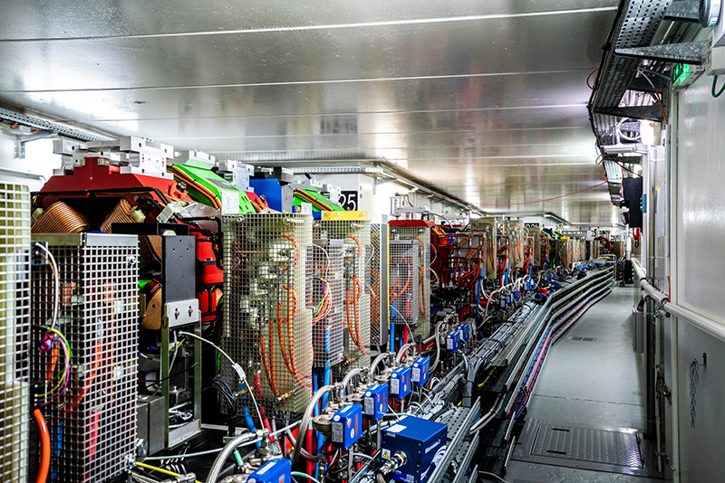
 Pantaleo Raimondi, professor at the Stanford Linear Accelerator Center, research technical manager, SLAC National Accelerator Laboratory and previously director, Accelerator and Source Division, ESRF.