Vacuum, radio-frequency, magnet and alignment experts offer a snapshot of some of the latest progress towards key FCC-ee components.
Vacuum system

The CERN vacuum group has been actively designing components for the FCC-ee vacuum system. Among them are 3D-printed synchrotron-radiation absorbers (SRAs), cold-sprayed copper “bosses”, which could be machined to obtain weld- and flange-free beam position monitor button electrodes (pictured), and plasma-sprayed thin titanium tracks to be used as a radiation-hard bake-out heating system. In parallel, a collaboration with a spin-off company from the University of Calabria is dealing with the implementation of shape-memory alloy flanges. The design of a 2 m-long vacuum chamber extrusion with one SRA is almost finalised, and a soon-to-be-built prototype will be tested at the KARA light source at KIT. We have also begun studying a vacuum chamber with a smaller inner diameter compared to the FCC-ee baseline, including its impact on the machine–detector interface and the booster. The length of the vacuum sectors has been optimised, and their integration in the overall tunnel design is under study. The vacuum group is also looking forward to prototyping the required NEG-coating set-up, as the vacuum chambers could be up to 12 m long and coating them in a vertical position, as is usually done, would be difficult, especially for industry when moving to mass production.
Robert Kersevan CERN.
Superconducting cavities
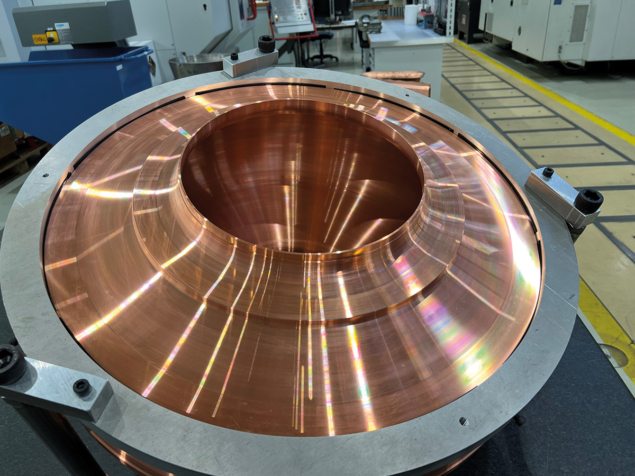
A key goal of R&D for the FCC superconducting radio-frequency (SRF) system, conducted by the CERN SY–RF, TE–VSC and EN–MME groups, is to optimise Nb/Cu technology for the fabrication of the cavities. Achieving high SRF performance in thin-film-coated cavities requires minimising substrate defects. Previous experiences show that imperfections located around electron beam welds in areas subjected to high magnetic field areas can constrain the quality factor of Nb/Cu cavities. To surpass the current limitations of Nb-coated cavities, a seamless configuration along with higher substrate quality and shape conformity is a promising alternative. Instead of traditional shaping methods such as deep-drawing or spinning, the ongoing use of techniques such as hydroforming and machining directly from the bulk material shows high potential for valuable results without altering the substrate. Moreover, it ensures effectiveness, repeatability and precision in the final shape of the cavity. Based on the impressive RF performance obtained from seamless Nb-coated 1.3 GHz cavities manufactured at CERN from bulk copper, the CERN teams are confident that such spectacular results will be repeated with a 400 MHz cavity (pictured) that is being machined as a preliminary prototype for the FCC RF study.
Said Atieh CERN.
HTS main arc magnets
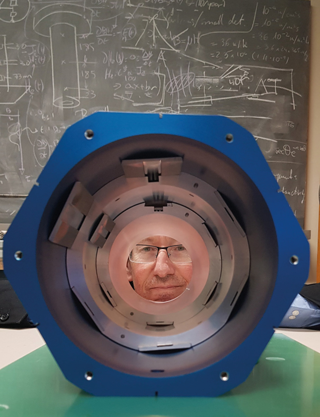
At the end of 2023, the first demonstrator of a high-temperature superconductor (HTS) sextupole designed for the FCC-ee arcs was fabricated at CERN (pictured). Built using novel technology from a CERN spin-off company, the magnet adopts a “canted cosine theta” design and is the first such device to use HTS rare-earth barium copper oxide (ReBCO) tape as its conductor – something that was long considered technically challenging. The main advantage of such a magnet is that ohmic losses (a significant source of electric power consumption for a normal-conducting accelerator) are reduced to zero, whereas refrigeration losses are much reduced compared to low-temperature-superconductor devices. Other advantages include increased performance due to the possibility of “nesting” magnets together, which is not possible for normal-conducting magnets that use iron to shape their magnetic fields. The increase in performance is such that up to 40% of the cost of the system can be recovered from the lower required RF voltage and therefore a smaller number of accelerating RF cavities. The magnet is the fruit of a CERN–PSI collaboration called FCCee-HTS4, funded through the CHART consortium in Switzerland. Future plans include the winding of the magnet at CERN, followed by tests for magnetic performance and quality.
Mike Koratzinos PSI.
Machine–detector interface alignment
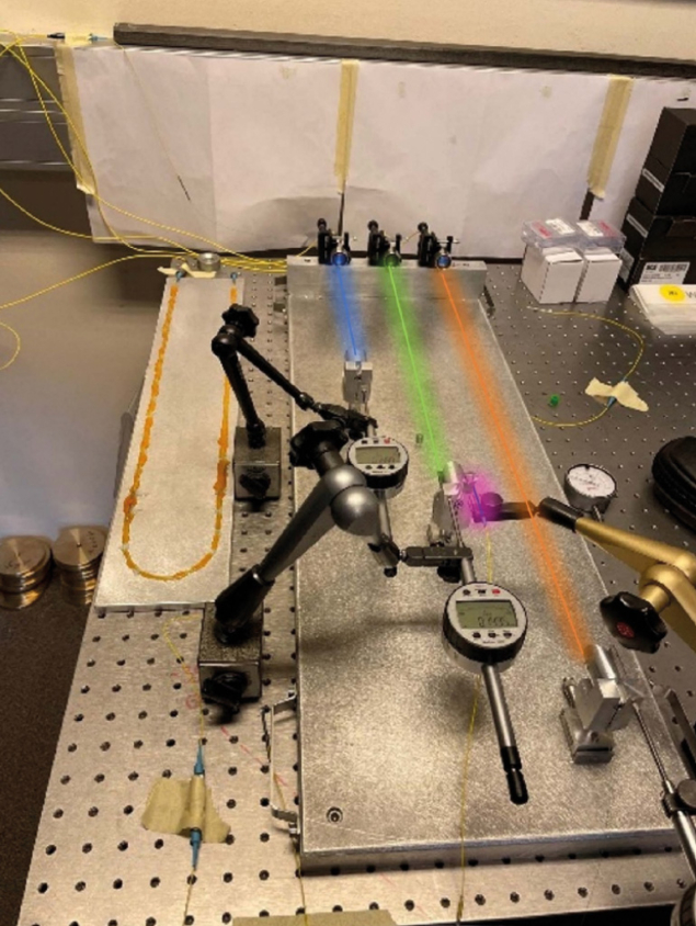
Designed to meet strict alignment requirements in the FCC-ee interaction points, the Machine Detector Interface (MDI) alignment system is a key element of the feasibility study. Challenging conditions – including extremely low temperatures, elevated radiation levels and limited space – hinder the deployment of standard survey equipment and sensors in this important region. New and exotic techniques and sensing systems have therefore been studied. The main solution, called in-lined multiplexed and distributed frequency scanning interferometry (IMD–FSI), uses an interferometer with a wavelength-sweeping laser source to measure multiple lengths along a single optical fibre, simultaneously and independently. A network of fibres can then be installed in a helical pattern to monitor the shape of components inside the MDI, such as the support of the screening solenoid. A prototype IMD–FSI system (pictured) has proved extremely promising, and the next step is a full fibre network implementation on a cylinder. This system could also be implemented in other regions of the collider, for example to monitor sensitive tunnel sections or other civil-engineering structures such as towers, dams and bridges.
Léonard Watrelot CERN.


