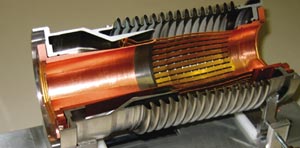
The LHC, with its “two in one” magnet structure cooled by superfluid helium for operation at 1.9 K, is its own prototype. It is therefore no surprise that problems arise that demand ingenious solutions, such as a newly invented diagnostic tool. Slightly larger than a ping-pong ball, it contains a tiny 40 MHz transmitter and fits just inside the beam pipe. Its purpose is to check interconnections within a sector (an eighth) of the machine without the need to open it up.
The need for such a device came to light when teams detected a fault in one of the interconnections during the warm-up of sector 7-8, the first to have been cooled to 1.9 K. One of the “plug in” modules responsible for the continuity of the electrical circuit in each of the LHC’s two vacuum chambers was damaged as the sector warmed up.
The plug-in modules ensure that mirror currents produced by the beams in the walls of the vacuum chambers can circulate freely. Any impedance would create hot points and reduce the intensity of the beam. The modules consist of copper “fingers” that slide along a cylinder and allow for contraction and expansion of the LHC’s components during cooling and warming. Each module expands or shrinks by about 40 mm, but the fingers always remain in contact with the cylinder in which they are sliding. In the faulty unit, the fingers failed to slide properly when the vacuum pipes returned to their original length, buckling into the space where the beam would normally pass.
It is difficult and time-consuming to open the magnet cryostats to check interconnections; it takes three weeks to open a sector and five weeks to close it again. X-ray studies revealed four more faulty modules in sector 7-8, but it was clear that a device that could check the space inside the beam pipes would be extremely useful. The solution is a ball 34 mm in diameter, which transmits at 40 MHz – the frequency of beam bunches in the LHC. A pumping system propels it through the vacuum pipe and beam-position monitors located every 50 m pick up the emitted signals. As the ball is a fraction smaller than the 36 mm beam screen, any obstacles will stop its progress and there will be no signal in the next monitor. This information allows the team to concentrate on the small number of interconnections between the two beam-position monitors concerned.
A first test on 13 September proved successful as the ball travelled 800 m through one vacuum pipe, detecting a sixth faulty module in the process. Altogether, only 6 out of 366 modules have proved to be damaged as sector 7-8 warmed up, and repairs are now in progress. An extra benefit is that the device allows the team to inspect the beam pick-ups around the ring.
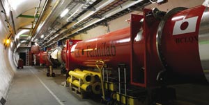
Elsewhere around the LHC, by the end of October teams had cooled a second sector to 80 K and begun pressure testing on a third. Any vacuum leaks that were found have been isolated and are currently being repaired. Cooling of further sectors should begin in November.
In addition, all of the inner triplet magnet assemblies have been repaired and are in position in the tunnel. Three of them had passed their pressure tests by the beginning of October. The cryogenic electrical distribution feedboxes (DFBX), which form part of the triplet assembly, have also undergone repairs. Only the triplet that was damaged during the spring test, plus one DFBX, have been removed from the tunnel. The others have been repaired in situ, a prerequisite for a solution.
Massimo Tarenghi has been described as “an excellent scientist and an energetic manager” by physics Nobel laureate Riccardo Giacconi, his colleague and fellow pupil of Beppo Occhialini. Tarenghi had wanted to be an astronomer since childhood. He graduated from the University of Milan with a degree in theoretical astrophysics, plus a thesis on gamma radiation from the galaxy core. In Arizona he took part in the first research work on large-scale galaxy distribution. He returned to Europe to lay the foundations of the European Organization for Astronomy in the Southern Hemisphere (ESO) at CERN, where ESO had its first offices.
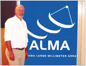
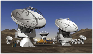
Like Giacconi, Tarenghi is a pioneer of the first large telescopes. He put forward the idea of building ESO’s Very Large Telescope (VLT) and directed the project from 1986 to 2002, commuting from ESO’s eventual premises in Garching, Germany, to the telescope’s site in the Paranal desert in Chile. He was appointed director of the Atacama Large Millimetric and Submillimetric Array (ALMA) in 2003, which is under construction in northern Chile on the Chajnantor plateau of the Atacama desert, the highest desert in the world. ALMA is a radio telescope made up of 64 antennas over an area of 25 km2 at an altitude of 5100 m.
As we climb by jeep from the Operation Support Facility (OSF), ALMA’s base camp at 2900 m, to the construction site at 5100 m, Tarenghi tells us: “When ALMA is ready in 2010, it will be to astronomers the equivalent of the LHC to particle physicists.” ALMA will be operated from the OSF, which will also house offices and laboratories. The ALMA assembly hall and the control room to operate the telescopes remotely are under construction. The circular structure of the buildings echoes the Atacameno architecture, honouring the 20,000 indigenous population who have lived in this extreme environment for 10,000 years. They will be given free access and job opportunities on the ALMA site.
By late August, three of the antennas had been shipped to Chile from Japan. Assembly and adjustment is taking place in the assembly hall, with the first of the three expected to be installed on the Chajnantor site before the end of the year. “Most of the work after commissioning will also be done here, just below 3000 m, which is surely more comfortable than above 5000 m, where there is 50% less oxygen in the air. It is also more convenient from a legal point of view,” says Tarenghi.
Before leaving the OSF, we went through medical screening to check blood pressure and oxygen levels and we collected oxygen bottles for the trip. With the magnificent background of the snow-capped Licancabur and Lascar volcanoes, the road to Chajnantor winds up through the Atacamenos archaeological sites and past examples of Echinopsis atacamensis, a rare protected species of centennial cacti that grows up to 9 m tall and only at altitudes of 3200 – 3800 m. The exceptionally flat access road is 20 km long and 12 m wide. It was built specially to enable the smooth transportation of the 64 antennas from the base camp to the Chajnantor site. The builders had to go around the cacti and archaeological remains to leave them untouched.
After stopping a few times to adjust to the altitude, we reach the ALMA site at 5100 m, and admire the view, which was literally breathtaking. The site has been chosen because of its ideal conditions for radio astronomy. Being isolated guarantees the total absence of other radio signals from human communications. The lack of humidity, which would otherwise absorb the millimetre and submillimetre emissions that ALMA is designed to catch, is also important. Tarenghi explains: “Most of the energy of the universe is made of the millimetric and submillimetric radio waves that ALMA is specialized in. In this area of the electromagnetic spectrum, half of the stars in the universe are formed inside intergalactic dust, which makes them invisible to optical telescopes. Here interesting astronomical phenomena take place, such as the birth of new stars and galaxies, immediately after the Big Bang. ALMA will be able to tell 90% of the history of the universe, which we still do not know. Moreover, in the submillimetric radio waves organic molecules are found, such as carbon and sugars. They are the origin of life in space, far from the Earth.”
On the Chajnantor we reach the Atacama Pathfinder Experiment (APEX), the first antenna installed on the ALMA site in 2004. It has a disc of 12 m diameter and weighs 120 tonnes. “APEX already obtained an important result in August 2006. It found fluorine, the first organic molecule to be found in the intergalactic dust of the Orion Nebula – a nice start that shows the scientific richness of this area of the spectrum. We have all the more reason to expect spectacular discoveries after 2010,” Tarenghi tells us.
In 2010 the site will be covered by 64 antennas similar to APEX, made in Europe, Japan and the US. Their signals will be combined by interferometry, making a combined radio telescope as big as the distance between two antennas. The site will have 197 concrete platforms to enable astronomers to lay out the 64 antennas according to their needs. The “compact” configuration, with a 150 m diameter around the centre of array (COFA), will be used to observe a slice of the sky at the maximum resolution (20 μm). The large array with a 3 km diameter will enlarge the visual range exactly like the zoom of a camera. (An array of diameter more than 10 km is also under construction) Tarenghi adds: “ALMA will be like Hubble on Earth. It’s a unique effort by Europe, the US and Japan. Like VLT, ALMA is different from other observatories not just for the size and number of telescopes in the array, but because it was designed from scratch as an astronomical research machine with all the telescopes being part of a large unit – like the accelerator complex at CERN, in a way.”
As former director of the VLT, Tarenghi can uniquely explain how the two projects differ. “VLT looks at the hot universe, ALMA is specialized in the cold universe. The difference is enormous. ALMA will explore areas that are not accessible to optical telescopes. In the millimetric radio waves, luminosity decreases and in the cold areas you have clouds, dust, disks where entire planetary systems are formed around stars. ALMA will be able to see the first galaxies in the universe as they were born around 14 billion [thousand million] years ago,” says Tarenghi.
He also explains to us why ALMA will be able to see the origin of life in space. The submillimetre region that ALMA specializes in is also the area where organic molecules are born and where planets form around other stars. ALMA will detect the emission of the atmospheres of other planets and will be able to find the presence of life. “Through the physical and chemical analysis of the atmosphere, ALMA will detect the presence of water, find out when dust grains formed and reconstruct the molecular history of the universe,” he says. “It will map the presence of water to the extreme limits of the universe and stand the highest chance, compared with any other instrument, to find life on other planets.”
The real innovation that ALMA will bring about is a radical change in the way astronomers work. “ALMA will be an all-rounder, an observatory open to all astronomers, irrespective of their specialization,” says Tarenghi. “Instead of sharing observation time, astronomers will have access to ALMA’s data. Like LEP or the LHC, ALMA will provide access to scientific data that can be used by the entire community, including theoreticians who want to test a theory. This is a huge new step in astronomy.”
The goals of ALMA reflect the challenges in astronomy today. Tarenghi tells us: “We are ignorant of the way planetary systems are formed, we do not know how the first objects were formed and what they looked like, what is the birth rate of stars in the universe. We know the first galaxies were made of just hydrogen and the second generation of heavier elements, but the process that gave origin to the formation of planets was born from a sequence of birth and death of stars that we do not know with accuracy. Only by going to large distances with telescopes that can perform both a physical and chemical analysis, we will be able to understand the mechanism that formed stars and reconstruct the history of the stars’ birth rate.” Investigating dark matter and energy are also challenges for ALMA, and are shared with experiments at the LHC. “These phenomena require a detailed knowledge of the large-scale structures of the universe. Only instruments like ALMA and telescopes like VLT, which can reach the limits of the warm universe, will give us an idea, as they can provide more data from different observation sources,” concludes Tarenghi. It seems that ALMA, like the LHC, is set to give us a much clearer view of the nature of the universe.
Using its first station of distributed radio antennas, the Low Frequency Array (LOFAR) radio telescope has successfully detected the pulsar PSR B0329+54. The measurement took 15 minutes on 14 June and used only six of the prototype high-band antennas recently installed in the eastern part of the Netherlands. The results demonstrate the technical performance of the antennas.
LOFAR will be the largest radio telescope ever built, using a new concept based on a vast array of simple omni-directional antennas. The idea is to digitize the signals before sending them to a central digital processor where software will combine them to create the effect of a large conventional antenna. When finished, it will consist of 15,000 small antennas, distributed to more than 77 stations in the north east of the Netherlands and nearby parts of Germany. The array will operate at the lowest frequencies that can be observed from Earth, at 10–240 MHz. Plans exist for the extension of the array beyond its initial 100 km scale, by building stations further into Germany and also in the UK, France, Sweden, Poland and Italy.
One important area of research, in addition to more conventional astronomy, will be the detection of extensive air showers originating from high-energy cosmic rays, and perhaps even neutrinos. Researchers have known since the 1960s that these showers produce radio signals that are detectable for cosmic-ray energies above 1017 eV. The radio emission comes from charged particles in the shower, mainly electrons and positrons, which are deflected in the Earth’s magnetic field and produce coherent synchrotron radiation. Electronic devices in the 1960s were not sensitive enough for reliable measurements of the radio emission. However, researchers have now developed new observational techniques and radio receiver systems – such as those that LOFAR employs. Through its observations, LOFAR should be able to study the longitudinal development of air showers and reconstruct the original directions of the incident cosmic rays.
Two other European experiments – CODALEMA in France, and LOPES in Germany – have already confirmed that radio detection techniques can be used to observe extensive air showers induced by cosmic rays. In addition, the Auger collaboration in Argentina is testing the same technique, with plans to implement a large array of antennas in conjunction with the existing air-Cherenkov detectors.
The LHC is not yet up and running, but already physicists and engineers in Europe, Japan and the US are working towards upgrades for the machine. In the US, the LHC Accelerator Research Programme (LARP) reached a major milestone in July when Brookhaven National Laboratory (BNL) successfully tested the first long racetrack shell (LRS) magnet, named because of its shape. The LRS magnet is a precursor of an upgraded superconducting quadrupole planned for the LHC.
The US group is working on strategies to upgrade the inner triplet quadrupole magnets that perform the final focusing of the particle beams prior to collision. These magnets are close to the interaction points, so they must be built to withstand high doses of radiation. An upgraded, higher-luminosity LHC will mean a hotter environment for these magnets.
Because upgraded inner triplets will need to operate at both a higher temperature and magnetic field, the US team, from BNL, Fermilab and Lawrence Berkeley National Laboratory, is evaluating niobium-tin (Nb3Sn) technology for the magnet coils, rather than the well-established niobium-titanium that is used in the current LHC magnets. However, the material is difficult to work with. The Next European Dipole research activity is also investigating Nb3Sn conductors for use in upgraded LHC magnets as part of the Coordinated Accelerator Research in Europe programme.
The LRS magnet is the first accelerator-style Nb3Sn magnet to be fabricated significantly longer than 1 m. At 3.6 m long, it approaches the length that will be needed for the LHC. BNL fabricated the coils for the LRS, and LBNL designed and fabricated the support structure. Fermilab contributed project management, conductor characterization, insulation development and insulated cable for a practice coil.
The first of these magnets, LRS01, was tested in July at BNL. “Training” the magnet (or subjecting it to repeated quenches) started above 80% of what is estimated to be the magnet’s maximum current density of 10.6 kA. After five quenches, the current reached 91% of the estimated maximum, corresponding to a coil peak field of 11 T.
The LRS01 magnet provides key information on the fabrication of long Nb3Sn and the optimization of shell-based support structures. The next step for LARP will be to build the Long Quadrupole. This will be the first-ever 4 m-long Nb3Sn accelerator-type magnet of its kind.
Measurements at RHIC at Brookhaven National Laboratory (BNL) have provided the first observations at a particle collider of a long-anticipated physical process that may eventually limit the performance of the LHC at CERN. Known as bound-free pair production, the process leads to the formation of one-electron ions that stray out of the beam and might deposit enough energy to quench the LHC’s superconducting magnets. It is thus vitally important to estimate the effect at the LHC.
RHIC typically collides gold nuclei at an energy of 19.7 TeV (100 GeV/nucleon) and, in its heavy-ion programme, the LHC will collide lead nuclei at 574 TeV (2759 GeV/nucleon). The main aim in these heavy-ion collisions is to “melt” the constituent protons and neutrons of the nuclei into a plasma of strongly interacting quarks and gluons. However, heavy-ion collisions also provide access to electromagnetic forces of phenomenal intensity, as relativistic length contraction dramatically squashes the electric field lines emerging from each highly charged nucleus into a flat pancake shape. When these “pancakes” interact, large numbers of electron–positron pairs are ripped out of the vacuum. In some cases, the electron of the pair is attached to one or other nucleus, converting a small fraction of the beam to one-electron ions. These soon stray from the path of the main beam and are lost in a well-defined patch of the beam-pipe surface.
The beam loss initiates a shower of particles (hadrons) that cause localized heating. At RHIC, the rate and energy of the collisions and the field in the magnets are all low enough that there is no danger of the magnets quenching. At the LHC, however, the heating will be several thousand times greater (up to 25 W) and researchers predict that the process will be a direct limit on the luminosity of lead-ion collisions. The LHC calculations depend not only on the theoretical cross-section but also tracking of ions to their impact points, the development of the hadronic showers, the propensity of the magnets to quench and the response of beam-loss monitors outside of the cryostats.
A team from CERN, BNL and Lawrence Berkeley National Laboratory has now measured this process for the first time, using beams of 6.3 TeV copper nuclei at RHIC and an array of photodiodes to detect the showers (Bruce et al. 2007). The team mounted the diodes on the outside of the magnet cryostat downstream from the interaction region for one of the experiments (PHENIX).
The data correlated well in time with the measured luminosity in RHIC, and were localized in position, close to the predicted impact point. The count rates in the photodiodes varied from 1 to 20 Hz, depending on their position and luminosity, with the maximum at 140.5 m from the interaction point. The results agree reasonably well with predictions, validating the LHC methodology and confirming the order of magnitude of the theoretical cross-section.
The circulating beams will store an unprecedented amount of energy when the LHC is in operation. If even a small fraction of this beam deviates from the correct orbit, it may induce a quench in the superconducting magnets or even cause physical damage to system components. The LHC beam-loss monitoring (BLM) system is the key to protecting the machine against dangerous beam “losses” of this kind.
The BLM system generates a beam abort trigger when the measured rate of lost beam exceeds pre-determined safety thresholds. The lost beam particles initiate hadronic showers through the magnets, which are measured by monitors installed outside of the cryostat around each quadrupole magnet. About 4000 BLMs – mainly ionization chambers – will be installed around the LHC ring. They are the result of a successful collaboration between CERN and the Institute for High Energy Physics (IHEP) in Protvino, Russia. CERN developed the monitors and IHEP manufactured them during the past year, using industry-produced components.
Signal speed and robustness against aging were the main design criteria. The monitors are about 60 cm long with a diameter of 9 cm and a sensitive volume of 1.5 l. Each one contains 61 parallel aluminium electrode plates separated by 0.5 cm and is filled with nitrogen at 100 mbar overpressure and permanently sealed inside a stainless-steel cylinder. They operate at 1.5 kV and are equipped with a low-pass filter at the high-voltage input. The collection time of the electrons and ions is 300 ns and 80 μs, respectively.
The radiation dose on the detectors over 20 years of LHC operation is estimated at 2 × 10⁸ Gy in the collimation sections and 2 × 10⁴ Gy at the other locations. To avoid radiation aging, production of the chamber components included a strict ultra-high vacuum (UHV) cleaning procedure. As a result, impurity levels from thermal and radiation-induced desorption should remain in the range of parts per million. Standardized test samples analysed at CERN periodically helped to check the cleaning performance.
The team at IHEP designed and built a special UHV stand to ensure suitable conditions for building the monitors. They performed checks throughout the production phase and documented the results. The quality of the welding is a critical aspect, so the team tested all of the welds for leak tightness at several stages. They also monitored constantly the vacuum and the purity of the filling gas. It was necessary to test the components before welding, and the assembled monitors during and after production, to ensure that the leakage current of the monitors stayed below 1 pA. Overall, IHEP achieved a consistently high quality for the monitors during the whole production period and kept to the tight production schedule. Tests at CERN’s Gamma Irradiation Facility of all 4250 monitors found fewer than 1% to be outside of the strict tolerance levels.
The first phase of commissioning BEPCII, the major upgrade of the Beijing Electron–Positron Collider (BEPC) came to a successful conclusion on 3 August, when the beam current reached 500 mA at 1.89 GeV. On the same day the researchers also completed mapping the combined magnetic field of the superconducting insertion magnets (SCQs) and the superconducting solenoid of the detector BESIII. This followed a series of studies that included the first collisions between beams in the electron and positron rings. The successful commissioning of the superconducting magnets and the cryogenics demonstrated that both systems were stable and up to design performance.
BEPCII consists of two storage rings, with a new ring built inside the original BEPC ring at the Institute of High Energy Physics, Beijing. The installation of all of the storage ring components, except for the SCQs, finished in early November 2006. Phase I commissioning, based on the conventional magnets in the interaction region, started on 13 November and the first electron beam was stored in the outer ring on 18 November. The ring provided beams to the users of the Beijing synchrotron radiation facility for more than a month, from 25 December.
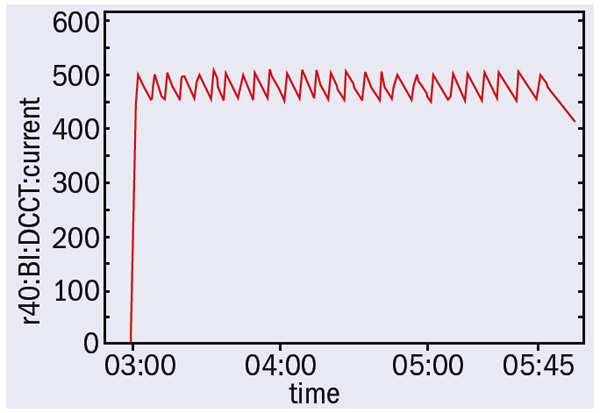
Commissioning both the electron and positron rings began in February 2007, and the first beam–beam collision occurred on 25 March. Optimization of the beam parameters followed, and on 14 May collisions occurred between beams of 100 mA each and 20 bunches per beam. The luminosity estimated from the measured beam–beam parameters reached a level comparable to that of the original BEPC, i.e. 1031 cm–2s–1 at the beam energy of 1.89 GeV. A second round of synchrotron radiation (SR) operation followed from 15 June to 31 July, with a beam current of about 200 mA and a lifetime of 6–7 hours. A slow orbit correction led to orbit ripples of less than 10 μm (figure 1).
Machine studies immediately followed the SR operation. With a bias-voltage applied to the radio-frequency coupler, the power provided by the superconducting cavity exceeded 100 kW and the beam current reached the design value of 250 mA at 2.5 GeV in SR mode. At the same time the beam current reached a stable 500 mA at 1.89 GeV without feedback (figure 2). The smooth commissioning demonstrated the good performance of the BEPCII hardware.
The construction of the BESIII detector has been smoothly progressing simultaneously. The assembly and testing of most of the sub-detectors, including the electromagnetic calorimeter barrel (CsI crystals) and the drift chamber, are now finished and ready for integration in BESIII.
After the Phase I commissioning, BEPCII shut down until the end of September for maintenance and the installation of the new interaction region components. Commissioning will resume in early October with the SCQs – and BESIII should be ready to be transported into the interaction region in the spring next year.
Discoveries at RHIC, at the Brookhaven National Laboratory (BNL), have captured worldwide attention. These findings have raised compelling new questions about the theory that describes the interactions of the smallest known components of the atomic nucleus. To address these questions at RHIC, we need to study rare processes. To do this, we must increase the collider’s luminosity, which is the rate at which ions collide inside the accelerator. BNL’s Collider-Accelerator Department (C-AD) is therefore investigating various upgrades, including the possibility of a luminosity upgrade through a process of electron cooling.
The electron-cooled RHIC, known as RHIC-II, would use low-emittance (“cool”), energetic and high-charge bunches of electrons to cool the ion bunches. This would increase the density of the ion bunches and lead to a higher luminosity. Achieving the necessary characteristics for the electron bunches will require using advanced accelerator techniques such as a high-brightness, high-current energy-recovery linac (ERL). A linac of this type may have other applications, including in an eRHIC (energetic electron ion collider at RHIC) and future light sources.
As RHIC operates, its luminosity goes down because of intra-beam scattering (IBS), which causes the bunches of gold ions to increase their longitudinal emittance and transverse emittance. This means that the bunches “heat up” and become more diffuse. A variety of other mechanisms can also induce emittance growth, regardless of IBS. These include instabilities of the ions’ motion, mechanical vibration of the magnets and the collisions themselves. Whatever the cause, more diffuse beams will produce lower luminosity and fewer collisions. So to improve luminosity, accelerator physicists at RHIC aim to eliminate, or reduce, the build-up of heat within the bunches by using electron cooling.
In 1966 Gersh Budker, of what is now the Budker Institute of Nuclear Physics (BINP) in Novosibirsk, invented electron cooling, which has been applied at numerous storage rings around the world. The idea is very intuitive: bring cold electrons into contact with the ions so that heat can flow from the warmer ions to the colder electrons. Cold electrons are produced by an electron source and are then accelerated to match precisely the speed of the ions in a straight section of the ring. Here, the two beams overlap and have a chance to exchange heat. The electrons are discarded after one pass and replaced by fresh electrons to continue the cooling process. At RHIC, which has two 3800 m rings, this straight section will be more than 100 m long. There are other differences between RHIC and previous electron-cooled rings: RHIC will be the first collider to be cooled during collisions and will be the first cooler using bunched electron beams.
To gain confidence in the calculated performance of the RHIC electron-cooler, the team at BNL has strived to develop dependable simulation techniques and benchmark them in experiments. Many institutes have helped in this challenge: BINP, JINR, Tech-X Corporation, Jefferson Laboratory, Fermilab, and the Svedberg Laboratory. The last two laboratories also helped in benchmarking experiments on their electron coolers.
One of the challenges of cooling RHIC lies with the machine’s high energy, which is around 10 times higher than any previous electron cooler (54 MeV electron energy for RHIC’s gold ions at 100 GeV per nucleon). This slows electron cooling because the cooling time is approximately proportional to the cube of the energy. The cooler therefore requires an electron beam that has a high energy and a high current. It must also cool over a long straight section, which means that a conventional DC electron accelerator cannot be used for cooling RHIC. For this reason, an ERL electron accelerator was adopted by BNL to produce electron bunches with a high charge (about 5 nC), a low emittance (under 3 μm normalized rms) and a high energy of 54 MeV. Another challenge is matching precisely – in position, speed and angular deviation – the electrons to the ions.
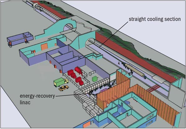
Figure 1 shows a possible layout of an electron cooler at RHIC. The cooling will take place in a 100 m straight section in the RHIC tunnel between two superconducting RHIC quadrupoles. The electron beam, generated by a 54 MeV superconducting RF ERL, will first travel with the beam in the anticlockwise ring and then loop back and travel with the beam in the clockwise ring. In doing so, the electron beam cools both rings.
The task of producing the necessary low-emittance and high-charge (high-brightness) electron bunches is even more difficult. The BNL team is currently working on a laser-photocathode superconducting radiofrequency source for the continuous production of a high-brightness electron beam that is capable of about 0.1 A. The design aims for a 0.5 A continuous average current. To make the ERL work without beam breakup, a superconducting accelerator cavity has been developed, which is capable of more than 3 A without beam-breakup, together with other technologies for accelerating a very high current efficiently.
Following several years of intensive R&D, we are confident that, according to our calculations, these techniques will increase the luminosity at RHIC and allow more sensitive, precision studies of the substructure of matter.
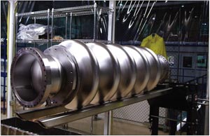
Figure 2 shows an ERL superconducting cavity and figure 3 gives the results of a cooling simulation. The five-cell cavity, developed by the C-AD and built by local industry (Advanced Energy Systems), is the first dedicated ERL cavity to be developed. After chemistry and testing at Jefferson Laboratory, it demonstrated 20 MeV acceleration at low-power investment.
The accelerator technologies that we are developing may also have applications at BNL beyond the RHIC-II upgrade. For example, the eRHIC upgrade would add electrons from an ERL to collide with the ion beams of RHIC. Another possible application could be at future “light source” facilities, using very high brightness X-rays to study the properties of materials and biological samples.
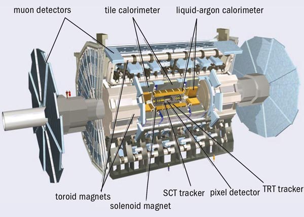
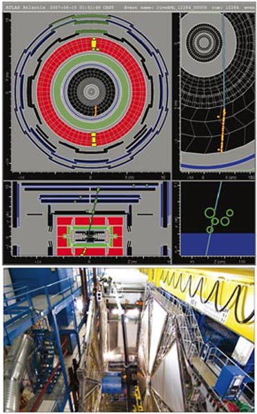
In the time since the vast underground cavern that houses the ATLAS experiment for the LHC was completed in 2003, it has gradually filled with the many different components that make up the largest-volume collider detector ever built (figure 1). Installation is due to be complete in early 2008. Meanwhile, commissioning the various subdetectors underground has been progressing in parallel. June saw the successful completion of the third “milestone week” (M3) in the global commissioning process. For the first time, the tests involved components from the tracking system as well as the calorimetry and muon detection systems, and each detector was operated from within the ATLAS control room.
The milestone weeks are dedicated to operating the experiment as a whole, from subdetector to permanent data storage, with an increasing number of subdetector systems involved at each stage. Even if a particular subdetector is not fully installed, these tests can still incorporate parts that are ready in order to exercise as many steps in the detection and data collection chain as possible. Keeping a sub-system that is still being installed in stable running conditions for many hours over many days is no small challenge. Multiply this by the 12 subdetectors involved, and add the computing, power and cooling infrastructure, detector control systems (DCSs) and safety systems, and it might seem questionable that it can work at all. But work it did during the M3 period, which in fact ran over two weeks from 4 to 18 June.
The first week of M3 was dedicated to the stable running of systems that had been integrated in previous exercises, with the emphasis this time on monitoring and exercising the formal procedures for running shifts when the experiment begins full operation in 2008. The subdetectors involved in this first week were the liquid-argon and tile calorimeters, together with part of the muon spectrometer (barrel and endcap). Each detector was initialized and monitored from a dedicated desk in the ATLAS control room, with the overall running controlled from the run-control desk.
The tile calorimeter, which basically consists of a steel-scintillator sandwich, is designed to measure the energy of hadrons emerging at angles greater than 25° to the beam. For hadron calorimetry between 25° and 5° in the endcaps, liquid argon and copper take over, with a different variation based on a tungsten absorber in the forward direction (less than 5°). Liquid argon also figures in the electromagnetic calorimeter, which is optimized for electrons and photons. However, in this case, lead (rather than copper) is used to initiate particle showers.
For the M3 tests, around 75% of the tile calorimeter and 50% of the liquid argon calorimeter were powered with high voltage and included in the final digital read-out. The tile calorimeter will provide a fast read-out for triggering when finally operational at the LHC, adding together calorimeter cells into trigger towers that point to the interaction point. In the M3 set-up, 500 trigger towers (around 25% of the final number) were used to provide a first-level trigger on cosmic muons, supplying signals to special trigger electronics for commissioning, which in turn delivered a trigger signal to the central trigger processor. This yielded a couple of cosmic events per minute that were read out by the central data acquisition (DAQ). During the run, a dozen or so non-expert “shifters” looked after routine operations, such as data and hardware monitoring, testing procedures as well as the detector systems.
The muon system for ATLAS is based on the huge toroid magnet system, with several different kinds of detector to register and track muons as they pass beyond the layers of calorimetery. Monitored drift tubes (MDTs) provide the precision measurements in the bending region of the magnetic field in both the barrel and the endcap region of the detector. They are complemented by trigger chambers – resistive plate chambers (RPCs) in the barrel and thin gap chambers (TGCs) in the endcap regions – which provide fast signals for the muon trigger and the second co-ordinate for the measurement of the muon momentum.
For the barrel muon detectors, sections of both the MDTs and the RPCs took part in the M3 tests using the final set-up for the high-voltage, low-voltage and gas systems, and all monitored by the central DCS. Some 27,000 drift tubes were read out during the run, which is more than the barrel muon read-out of the LEP experiments (e.g. ALEPH had approximately 25,000 muon channels) but is less than 10% of the final total for ATLAS. Two sectors of RPCs were used to provide a trigger on cosmic muons.
The integration of new components into the global system formed the main goal of week two, which saw the addition of detectors from the inner tracking system and more trigger equipment. The inner detector uses three different systems for tracking particles within the volume of a superconducting solenoid magnet inside the calorimeters. The tracking systems form three layers, the outermost being the transition radiation tracker (TRT) based on “straws” (4 mm diameter drift tubes). Silicon strip detectors in the semiconductor tracker (SCT) are used at radii closer to the beam pipe, while silicon pixel detectors form the innermost layer.
The barrel TRT was successfully installed and tested in October 2006. Since then a number of stand-alone and system tests combined with the SCT have taken place to characterize the detector. For M3, six TRT barrel modules – altogether 20,000 channels or 19% of the TRT barrel – were connected to the back-end read-out electronics and successfully integrated into the central DAQ. Steps were also taken towards the integration of the TRT DCS into the ATLAS DCS, and cosmic-ray data were collected in combination with other detectors by the end of the M3 period (figure 2).
Cooling for the SCT was not available during the M3 run, so this detector could not take part fully. However, its DAQ was nonetheless successfully integrated using some test modules installed adjacent to the SCT read-out driver (ROD) crates. Despite using only a small number of modules, M3 provided a valuable opportunity to exercise the final DAQ infrastructure and the functionality of the trigger timing in preparation for running with the full SCT.
On the second week of the run, the first-level calorimeter trigger (L1Calo) also joined the data collection, taking part for the first time in a milestone run, although not yet providing real triggers. For this initial test, the system consisted of one-eighth of the final set of preprocessor modules and one ROD. The pre-processor modules perform the analogue-to-digital conversion for L1Calo and will also identify the bunch-crossing that the signals have come from when there is beam in the LHC. Running this system was smooth and provided valuable experience of stable running with parts of the final trigger hardware integrated with the other ATLAS subsystems.
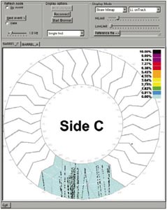
For the muon system, elements of the endcap wheels were brought into the trigger during the second week. The TGCs, which provide the level-1 trigger for the muon-endcaps, had already been integrated into the central trigger and DAQ system, but on 13 June some of them were used for the first time to provide a cosmic-ray trigger to other subdetectors, in particular endcap monitored drift tube chambers. This involved 1 out of the 72 sectors of TCGs, using final chambers, electronics equipment and DCS (figure 3). The alignment of the TGCs was sufficiently well known that triggers from cosmic rays were produced with good efficiency at a rate of 3 Hz.
The region of interest builder (RoIB) was another component of the final trigger hardware that was successfully integrated during M3. Although the first-level trigger decision is based on the multiplicity of objects, and not on their position, the first-level trigger processors do remember where they encountered objects passing their thresholds, and, for events accepted by the first-level trigger, they pass this information on to level 2. The role of the custom-built electronics forming the RoIB is to receive these region of interest fragments from the first-level muon and calorimeter trigger subsystems and the central trigger processor, and then to combine them into a single record that is passed on to the level-2 trigger supervisor. The initial hardware for the high-level trigger (level-2 and Event Filter) was also successfully integrated. This consisted of 20 level-2 nodes running cosmic algorithms (but not rejecting events) and 10 event filter nodes (without algorithm processing), which passed data to one of six subfarm output units (SFOs) in the final system. The SFO was able to write events to disk at a rate of up to 70 MB/s and subsequently transferred these files to CASTOR, the data storage on the CERN site, at a rate of around 35 MB/s.
M3 provided the first opportunity for Tier-0 processing to take part in a real data-taking exercise. The existing Tier-0 infrastructure, so far only used in large-scale tests decoupled from the on-line world, was adapted to the needs of M3 and run during almost the whole data-taking period. Its tasks were to pick up the data files written to CASTOR by the DAQ and to run the offline reconstruction. For the first time, the complete offline software chain could reconstruct cosmic-ray events from data in the calorimeters, the inner detector and part of the muon system (figure 4).
The full monitoring chain was also running, taking the different reconstructed objects as input and producing the relevant monitoring histograms for each subdetector in order to check its correct performance. In a subsequent processing step, monitoring histograms produced as outputs of the individual reconstruction jobs were also merged to allow data quality monitoring over longer periods of time.
Progress during M3 – the third “mile” – has demonstrated that almost all of the subsystems of ATLAS can work together in at least a fraction of their final size, and, in the case of the calorimeters, a large fraction. There are still a few more miles to go. The challenge will be to increase the system in size as commissioning continues while keeping the running-efficiency high and the failure-rate low.
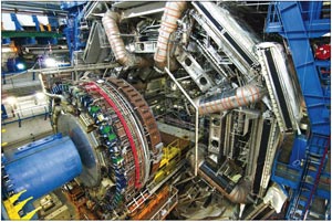
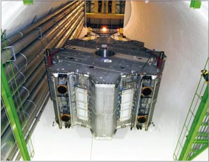
In the early hours of 13 June, the first of the two gigantic toroid magnet endcaps touched the ATLAS cavern floor. The second endcap followed suit on 12 July. With this delicate operation complete, the ATLAS collaboration has now finished lowering all of the large heavy pieces of detector into the cavern.
The last steps were not without challenges, particularly for the first endcap. These included removing a 5 m portion between the top of the main door and the roof to fit the 13 m high, 240 tonne endcap into the building. Once inside, it was lifted by a mobile crane and secured to two gantry cranes on either side of the entry shaft.
Another issue was that the endcaps were higher than the 2 × 140 tonne overhead travelling crane used to lower them down to the cavern floor. In order to secure an endcap to this crane, it first had to be suspended by the two gantry cranes and lowered 5 m to the correct height using a system of jacks. At the end of the 80 m journey down the shaft, each endcap was placed between the barrel part of the detector and the wheels of the endcap muon chambers with a precision of 2 mm and a margin of 10 cm on either side.
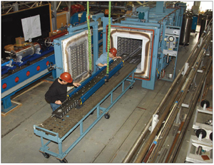
The LHCb collaboration has meanwhile completely installed, interconnected, pumped down and baked out all four sections of the LHCb beam pipe, which includes a section that connects to the vacuum vessel containing the VErtex LOcator (VELO). The largest of the four conical sections is composed of stainless steel and the others are made of beryllium to minimize background in the experiment. One of the more challenging tasks was the installation of the longest section of beryllium beam pipe (6 m) through the RICH2 detector in January, which used temporary rails to guide it through the inner tube with a leeway of only 4 cm. In February, a crane was used to lift the 160 kg stainless steel section and position it in the middle of the iron walls of the muon system on supports that align it with the beamline.
After all of the installation work, the next step was to pump the beam pipe down to a pressure of 10–7 mbar. During the following bake out and non-evaporable getter (NEG) activation, the VELO was heated to 150 °C and the NEG reached 220 °C to obtain an ultra-high vacuum inside the beam pipe. Once the bake-out was complete, the pressure had gone down to 10–11 mbar.
To provide the best experiences, we use technologies like cookies to store and/or access device information. Consenting to these technologies will allow us to process data such as browsing behavior or unique IDs on this site. Not consenting or withdrawing consent, may adversely affect certain features and functions.
Functional
Always active
The technical storage or access is strictly necessary for the legitimate purpose of enabling the use of a specific service explicitly requested by the subscriber or user, or for the sole purpose of carrying out the transmission of a communication over an electronic communications network.
Preferences
The technical storage or access is necessary for the legitimate purpose of storing preferences that are not requested by the subscriber or user.
Statistics
The technical storage or access that is used exclusively for statistical purposes.The technical storage or access that is used exclusively for anonymous statistical purposes. Without a subpoena, voluntary compliance on the part of your Internet Service Provider, or additional records from a third party, information stored or retrieved for this purpose alone cannot usually be used to identify you.
Marketing
The technical storage or access is required to create user profiles to send advertising, or to track the user on a website or across several websites for similar marketing purposes.