Commissioning the LHC is making steady progress towards the target of achieving a complete cool down by the middle of June, allowing the first injection of beams soon after. This will come almost exactly 19 years after the start up of LEP, the machine that previously occupied the same tunnel. The LHC’s first collisions will follow later.
Half of the LHC ring – between point 5 and point 1 – was below room temperature by the first week of April, with sectors 5-6 and 7-8 fully cooled. The next step for these sectors will be the electrical tests and powering up of the various circuits for the magnets. From late April onwards, every two weeks the LHC commissioning teams will have a new sector cooled to 1.9 K and ready for testing.
Sector 7-8 was the first to be cooled to 1.9 K in April 2007, and the quadrupole circuits in the sector were powered up to 6500 A during the summer. The valuable experience gained here allowed the hardware commissioning team to validate and improve its procedures and tools so that electrical tests on further sectors could be completed faster and more efficiently. Each sector has 200 circuits to test.
The next electrical tests were carried out on sector 4-5 from November 2007 to mid-February 2008. Once the temperature had been stabilized at 1.9 K by the beginning of December, the circuits were powered up to an initial 8.5 kA. The main dipole circuit was then gradually brought up to 10.2 kA during the last week of January 2008, with the main quadrupole circuits reaching 10.8 kA in February. At this current the magnets are capable of guiding a 6 TeV proton beam.
During this testing of sector 4-5, however, a number of magnet-training quenches occurred for both dipole and quadrupole circuits. Three dipoles in particular quenched at below 10.3 kA, despite having earlier been tested to the nominal LHC operating current of 11.8 kA. It appears that retraining of some magnets will be necessary, which is likely to take a few more weeks. CERN’s management, with the agreement of all of the experiments and after having informed Council at the March session, decided to push for collisions at an energy of around 10 TeV as soon as possible this year, with full commissioning to 14 TeV expected to follow over the winter shutdown. Past experience indicates that commissioning to 10 TeV should be achieved rapidly, with no quenches anticipated.
Sector 5-6 will be the next to cross the 10 kA threshold; electrical tests here began in April. Sector 4-5, meanwhile, was warmed up again to allow mechanics to connect the inner triplet magnets, which were modified after a problem arose during pressure testing last year.
India’s accelerator pioneers began to build the Calcutta cyclotron in the early 1970s but soon found that the industrial infrastructure was not geared up to provide the necessary level of technology. They had, for instance, difficulty in finding a suitable manufacturer for the essential resonator tank. The Garden Reach Ship Builders said they could build watertight ships but had no experience in making tanks that had to be airtight, maintaining a high vacuum (10–6 torr). But build it they did, and the cyclotron was commissioned in June 1977. It is still working well and has catered for almost two generations of experimental nuclear physicists.
In the early 1980s some of us wanted to build a detector to be used at CERN’s SPS to register photons as signals of quark–gluon plasma (QGP), formed in the collision of two nuclei at laboratory energies of typically 200 GeV/nucleon. The protons and neutrons of an atomic nucleus at this energy should “melt” into their fundamental constituents, the quarks and gluons, rather as in the primordial universe a few microseconds after the Big Bang.
The adventure of building a photon multiplicity detector (PMD) was inspiring but not easy. The sheer size and complexity was daunting; the required precision even more so. All of the pundits (i.e. distinguished elderly scientists on funding committees) unanimously declared the project impossible and too ambitious, and generally questioned our credibility. Undaunted, we refused to accept their verdict and against all odds received our initial modest funding.
We did the design in India. The Cyclotron Centre in Calcutta; the Institute of Physics in Bhubaneswar; the universities of Rajasthan and Jammu, and Panjab University joined in. In a short time the group built the PMD, with 55,000 pads, each consisting of a 1–2 cm2 plastic scintillator. Optical fibres inserted diagonally in each pad picked up the photons – the possible signals of QGP.
The PMD was a great success, unprecedented in modern India, particularly on this scale. It required all kinds of creative innovation, with the best suggestions coming from the youngest members of the team. Almost overnight, India became a key player on the world stage in this field. This kind of science and the associated precision technology, which had so far remained dormant, began to flourish; there was no looking back.
The PMD later went through a basic design change with the introduction of a “honeycomb” design, and it was shipped across the Atlantic for the STAR experiment at RHIC at the Brookhaven National Laboratory. With a reputation already established at CERN, entry into RHIC posed no problem whatsoever. The PMD has already accumulated a vast quantity of data at RHIC, with good statistics. Complemented by the results from the PHENIX detector, photons look promising as signals of QGP.
Meanwhile, in India we moved from the room-temperature cyclotron to a superconducting cyclotron using niobium–titanium superconducting wire. Hunting for a suitable company to build our cryostat was an adventure. We searched all of India, but drew a blank. Despite our determination we failed to find a suitable company to build the cryostat, and eventually turned to Air Liquide, France, but not without hiccups. We learned how to manage large-scale liquid helium and maintain a steady liquid helium temperature.
Finally, on 11 January 2005, the magnet became superconducting at a temperature of around 4.2 K and maintained the superconducting state for months. It was a fantastic experience. All of January felt like a carnival. We had made the leap from room-temperature technology to large-scale cryogenic technology.
Meanwhile at CERN, the LHC was looming large on the horizon, with a heavy-ion programme and the ALICE detector. We were thrilled – here was scope for the old workhorse, the PMD, in a more sophisticated guise. Aligarh Muslim University and IIT, Bombay, also joined in our quest. My colleagues at Saha Institute went further, and wanted to participate in the dimuon spectrometer. Colleagues who had remained dormant or busy with routine jobs, were suddenly inspired. They went on to design the MANAS chip for the muon arm. An Indian company, the Semi Conductor Complex Ltd in Chandigarh, enthusiastically offered to build the hardware. After much debate, the MANAS chip became central to the ALICE muon arm and was accepted worldwide.
Last time at CERN, walking in the shadow of ALICE, marvelling at its size and the immaculate precision with which the work was done, I felt like Alice in Wonderland, with “quarkland” beckoning on the horizon.
In the 1970s, India was still a spectator in the world theatre of high science. Individuals who migrated to other parts of the world sometimes excelled. In India, people were proud of them but remained convinced that such feats could not be accomplished back home. In the 1980s, however, there was a major paradigm shift in our mind set. We began to dream of competing with the world from India.
By the beginning of the 21st century, India was no longer a spectator but a significant player on the world stage. The glamour of individual excellence had been replaced by the wisdom of collective effort. We had turned mature and ambitious. What I have presented is a chronicle of that evolution. I am proud and grateful to be a witness and indeed a participant in this evolving panorama.
The voyage that started almost 30 years ago continues with resolve from LHC to FAIR to an ILC and further, making the impossible possible and turning dreams to reality.
Traditionally at CERN, teams on each experiment, and in some cases each subdetector, have independently developed a detector-control system (DCS) – sometimes known as “slow controls”. This was still the case for the experiments at LEP. However, several factors – the number and geographical distribution of development teams, the size and complexity of the systems, limited resources, the long lifetime (20 years) and the perceived similarity between the required systems – led to a change in philosophy. CERN and the experiments’ management jointly decided to develop, as much as possible, a common DCS for the LHC experiments. This led to the setting up in 1997 of the Joint Controls Project (JCOP) as a collaboration between the controls teams on the LHC experiments and the support groups in CERN’s information technology and physics departments.
The early emphasis in JCOP was on the difficult task of acquiring an understanding of the needs of the experiments and agreeing on common developments and activities. This was a period where disagreements were most prevalent. However, with time the collaboration improved and so did progress. Part of this early effort was to develop a common overall architecture that would become the basis of many of the later activities.
The role of JCOP
In parallel, the JCOP team undertook evaluations to assess the suitability of a number of technologies, primarily commercial ones, such as OLE for Process Control (OPC), the field buses CANBus and ProfiBus, commercial programmable logic controllers (PLCs), as well as supervisory control and data acquisition (SCADA) products. The evaluation of SCADA products eventually led to the selection of the Prozessvisualisierungs und Steuerungs System (PVSS) tool as a major building block for the DCS for experiments. The CERN Controls Board subsequently selected PVSS as the recommended SCADA system for CERN. In addition, and where suitable commercial solutions were not available, products developed at CERN were also evaluated. This led to JCOP’s adoption and support of CERN’s distributed information manager (DIM) middleware system and the SMI++ finite-state machine (FSM) toolkit. Furthermore, developments made in one experiment were also adopted by other experiments. The best example of this is the embedded local monitor board (ELMB) developed by ATLAS. This is a small, low-cost, high-density radiation-tolerant input/output card that is now used extensively in all LHC experiments, as well as in some others.
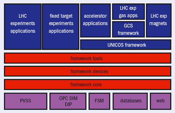
One major thrust has been the development of the so-called JCOP framework (FW) (figure 1). Based on specifications agreed with the experiments, this provides a customized layer on top of the technologies chosen, such as PVSS, SMI++ and DIM. It offers many ready-to-use components for the control and monitoring of standard devices in the experiments (e.g. CAEN high voltage, Wiener and CAEN low voltage, the ELMB and racks). The FW also extends the functionality of the underlying tools, such as the configuration database tool and installation tool.
These developments were not only the work of the CERN support groups but also depended on contributions from the experiments. In this way the development and maintenance was done once and used by many. This centralized development has not only significantly reduced the overall development effort but will also ease the long-term maintenance – an issue typically encountered by experiments in high-energy physics where short-term collaborators do much of the development work.
As figure 1 shows, the JCOP FW has been developed in layers based on a component model. In this way each layer builds on the facilities offered by the layer below, allowing subdetector groups to pick and choose between the components on offer, taking only those that they require. The figure also illustrates how the JCOP FW, although originally designed and implemented for the LHC experiments, can be used by other experiments and applications owing to the approach adopted. Some components in particular have been incorporated into the unified industrial control system (UNICOS) FW, developed within the CERN accelerator controls group (Under control: keeping the LHC beams on track). The UNICOS FW, initially developed for the LHC cryogenics control system, is now used for many applications in the accelerator domain and as the basis for the gas-control systems (GCS) for the LHC experiments.
In addition to these development and support activities, JCOP provides an excellent forum for technical discussions and the sharing of experience across experiments. There are regular meetings, both at the managerial and the technical levels, to exchange information and discuss issues of concern for all experiments. A number of more formal workshops and reviews have also taken place involving experts from non-LHC experiments to ensure the relevance and quality of the products developed. Moreover, to maximize the efficiency and use of PVSS and the JCOP FW, JCOP offers tailor-made training courses. This is particularly important because the subdetector-development teams have a high turnover of staff for their controls applications. To date, several hundred people have attended these courses.
As experiments have not always tackled issues at the same time, this common approach has allowed them to benefit from the experience of the first experiment to address a particular problem. In addition, JCOP has conducted a number of test activities, which cover the testing of commonly used commercial applications, such as various OPC servers, as well as the scalability of many of the supported tools. Where the tests indicated problems, this provided feedback for the tool developers, including the commercial suppliers. This in turn resulted in significant improvements in the products.
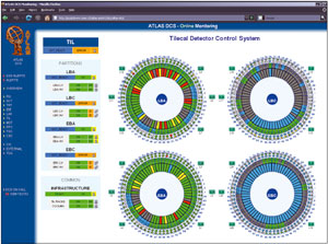
Although JCOP provides the basic building blocks and plenty of support, there is still considerable work left for the subdetector teams around the world who build the final applications. This is a complex process because there are often several geographically distributed groups working on a single subdetector application, and all of the applications must eventually be brought together and integrated into a single homogeneous DCS. For this to be possible, the often small central experiment controls teams play a significant role (figure 2). They not only participate extensively in the activities of JCOP, but also have other important tasks to perform, including development of guidelines and recommendations for the subdetector developments, to ensure easy integration; customization and extension of the JCOP FW for the experiment’s specific needs (e.g. specific hardware used in their experiment but not in the others); support and consultation for the subdetector teams; development of applications for the monitoring and control of the general experiment infrastructure e.g. for the control of racks and environmental monitoring.
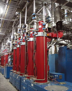
As well as selecting, developing and supporting tools to ease the development of the DCSs, there have been two areas where complete applications have been developed. These are the detector safety systems (DSS) and the gas control systems (GCS). The DSS, which is based on redundant Siemens PLCs and PVSS, has been developed in a data-driven manner that allows all four LHC experiments to configure it to their individual needs. Although not yet fully configured, the DSS is now deployed in the four experiments and has been running successfully in some for more than a year.
The approach for the GCS goes one step further. It is also based on PLCs (Schneider Premium) and PVSS, but the PLC and PVSS code of the 23 GCSs is generated automatically using a model-based development technique. In simple terms, there is a generic GCS model that includes all possible modules and options, and each GCS application is defined by a particular combination of these modules and options. The final GCS application is created by selecting from a set of predefined components and configuring them appropriately using an application builder created for the purpose. All 23 GCSs have been generated in this way and are now deployed.
At the time of writing, the four LHC experiment collaborations were all heavily engaged in the commissioning of their detectors and control systems. To date, the integration of the various subdetector-control systems has proceeded relatively smoothly, owing to the homogeneous nature of the subdetector implementations. However, that is not to say that it has been problem free. Some issues of scaling and performance have emerged as the systems have increased in size, with more and more of the detectors being commissioned. However, thanks to the JCOP collaboration, it has been possible to address these issues in common for all experiments.
Despite some initial difficulties, the players involved see the approach described in this article, as well as the JCOP collaboration, as a success. The key here has been the building of confidence between the central team and its clients through the transparency of the procedures used to manage the project. All of the partners need to understand what is being done, what resources are available and that the milestones will be adhered to. The benefits of this collaborative approach include less overall effort, through the avoidance of duplicate development; each central DCS and subdetector team can concentrate on their own specific issues; easier integration between developments; sharing of knowledge and experience between the various teams; and greater commonality between the experiment systems enables the provision of central support. In addition, it is easier to guarantee long-term maintenance with CERN-based central support. Compared with previous projects, JCOP has led to a great deal of commonality between the LHC experiments’ DCSs, and it seems likely that with more centralized resources even more could have been achieved in common.
Could the JCOP approach be applied more widely to other experiment systems? If the project has strong management, then I believe so. Indeed, the control system based on this approach for the LHCb experiment is not limited to the DCS but also covers the complete experiment-control system, which includes the trigger, data-acquisition and readout systems as well as the overall run control. Only time will tell if this approach can, and will, be applied more extensively in future projects.
Control systems are a huge feature of the operation of particle accelerators and other large-scale physics projects. They allow completely integrated operation, including the continuous monitoring of subsystems; display of statuses and alarms to operators; preparation and automation of scheduled operations; archiving data; and making all of the experimental data available to operators and system experts. The latest news from projects around the world formed the main focus of the 11th International Conference on Accelerator and Large Experimental Physics Control Systems (ICALEPCS), which took place on 13–19 October in Knoxville, Tennessee. More than 360 people from 22 countries attended the meeting hosted by the Oak Ridge National Laboratory (ORNL) and the Thomas Jefferson National Accelerator Facility at the Knoxville Conference Center. The 260 presentations, including 71 talks, confirmed the use of established technologies and reviewed their consolidation. Excellent poster sessions also provided plenty of opportunity for discussions with the authors during the coffee breaks.
The weekend prior to the conference saw three related meetings. Almost 50 people attended the Control System Cyber-Security workshop, where eight major laboratories presented and discussed current implementations and future prospects for securing control systems. All have acknowledged the risk and all follow a “defence-in-depth” approach, focusing on network protection and segregation, authorization and authentication, centralized PC installation schemes and collaboration between information-technology and controls experts.
Approaches to control systems
In parallel, 200 people attended meetings of the collaborations developing the open-source toolkits EPICS and TANGO. The EPICS collaboration in particular has grown since previous ICALEPCS meetings. The contributions presented at the conference showed that these two toolkits are the most widely used and are the predominant choice for many facilities. For example, EPICS has recently been selected for use at the Spallation Neutron Source (SNS) at ORNL, while the control system of the ALBA light source in Spain will be based on TANGO.
Alternative solutions employ commercial supervisory control and data acquisition (SCADA) products for control systems. This is the case, for example, at CERN, the Laser Mégajoule project and the SOLEIL synchrotron. At CERN, the cryogenics system for the LHC and the LHC experiments, among others, make extensive use of commercial SCADA systems. The combination of their use with appropriate software frameworks developed in common has largely facilitated the design and construction of these control systems. They are currently being scaled up to their final operational size – a task that has gone smoothly so far (Under control: keeping the LHC beams on track and Detector controls for LHC experiments).
Independent of the approach adopted, the controls community has focused strongly on the software-development process, taking an increasing interest in risk reduction, improved productivity and quality assurance, as well as outsourcing. The conference learned of many efforts for standardization and best practice, from the management of requirements to development, implementation and testing. Speakers from CERN, for example, explained the benefits of the adoption of the Agile design and programming methodology in the context of control-system development.
The ITER tokamak project in Cadarache, France, has taken an approach that uses a unified design to deal with the static and dynamic behaviour of subsystems. The operation of ITER requires the orchestration of up to 120 control systems, including all technical and plasma diagnostic systems. ITER will outsource a large fraction of these control systems, which will be procured “in kind” from the participating teams. Outsourcing also played a major role in the Australian Synchrotron and it involved co-operation between research institutions and industrial companies to enhance and optimize the functionality of their control-system products. Such collaboration needs the definition of strict acceptance criteria and deadlines, but it also allows outsourcing of the risk. The Mégajoule project tested its subcontracting process within a small “vertical slice”, before adapting all of the outsourcing and the integration process to the full-scale system. The Atacama Large Millimetric and Submillimetric Array has provided further lessons about the successful organization of a distributed team and integration of different objects. The project enforced a common software framework on all participating teams, and the integration process focused on functionality rather than on the subsystems.
In addition to the software frameworks for control systems, there are many plug-ins, tools and utilities under development, using, in particular, the Java language. For example, EPICS employs Java at all levels from the front-end Java input/output (I/O) controllers to the supervision layer. Java is now a top candidate for new developments, owing mostly to its productivity and portability, not only for graphical user interfaces (GUIs) and utilities but also for applications that are calculation intensive. The accelerator domain has integrated more advanced Java-related techniques successfully. SLAC, for example, has benefited from the open-source Eclipse technologies, and the Java-based open-source Spring is being deployed in the LHC accelerator control systems at CERN (Under control: keeping the LHC beams on track). However, somewhat contrarily to these common efforts, individual projects have also developed a variety of new electronic logbooks and custom GUI builders.
The flexibility and portability of Java are becoming increasingly combined with the extensible markup language XML. With interoperability in mind, the growing (and correct) usage of XML and associated technologies provides a good basis for openness, data exchange and automation, rather than simply for configuration.
An example of this openness is the adoption of industrial solutions for data management. Modern control systems have seen a rapid growth in data to be archived, together with rising expectations for performance and scalability. File-based or dedicated solutions for data management are reaching their limits, so these techniques are now being replaced by high-performance databases, such as Oracle and PostgreSQL. These databases not only record the parameters of control systems but also are used for administration, documentation management and equipment management. In addition to these well established technologies, some users have chosen ingenious approaches. For example, SPring-8 in Japan has a geographic information system integrated into its accelerator management (figure 1). The Google Maps-like system allows localizing, visualizing and monitoring of equipment in real time, and it has opened up interesting perspectives for the control systems community.
Hardware becomes soft
On the hardware side, VME equipment shows an increased use of embedded controllers, such as digital signal processors and field-programmable gate arrays. Their flexibility brings the controls software directly onto the front end, for example, as cross-compiled EPICS I/O controllers. The development of radiation hard front-ends, for example, for the Compact Linear Collider study and the LHC at CERN, have presented other challenges. Timing systems have also had to face new challenges: the LHC requires independent and asynchronous timing cycles of arbitrary duration; timing distributions, for the accelerators at SOLEIL or the Los Alamos Neutron Science Center, for example, are based on common networks with broadcasting clocks and event-driven data; and modern free-electron lasers (FELs), such as at SPring-8, depend on timing accuracies of femtoseconds to achieve stable laser beams.
FELs and light sources were the main focus of several status reports at the conference. The X-ray FEL project at SPring-8 has implemented its control system in MADOCA, a framework that follows a three-tier control model. The layers consist of an interface layer based on DeviceNet programmable logic controllers and VME crates; communication middleware based on remote procedure calls; and Linux consoles for the GUIs. The control system for the Free-electron Laser in Hamburg (FLASH) at DESY provides bunch-synchronized data recording using a novel integration of a fast DAQ system. The FLASH collaboration carried out an evaluation of the front-end crates used in the telecoms industry, which suggested that they had more reliable operation and integrated management compared with VME crates. The collaboration for the ALICE experiment at the LHC reported on progress with its control system, which is currently being installed, commissioned and prepared for operation, due to start later this year. Other status reports came from the Facility for Antiproton and Ion Research at GSI and the Diamond Light Source in the UK.
The conference concluded with presentations about the new developments and future steps in the evolution of some of the major controls frameworks. These underlined that the ICALEPCS conference not only confirmed the use of established technologies and designs, in particular EPICS and TANGO, but also showed the success of commercial SCADA solutions. Control systems have become highly developed and the conference reviewed consolidation efforts and extensions thoroughly. The social programme included a dinner with bluegrass music and an excellent tour of the SNS, the world’s most intense pulsed accelerator-based neutron source, which rounded off the meeting nicely. Now the controls community awaits the 12th ICALEPCS conference, to be held in Kobe, Japan, in autumn 2009.
Accelerator physicists at Brookhaven National Laboratory have developed a way to apply the technique of stochastic cooling to the beams in the Relativistic Heavy Ion Collider (RHIC). This is the first time that the technique for concentrating a particle beam has been used in a machine where the particles are bunched. The results of the tests in 2007, which offer a “fast track” to upgrading the luminosity at RHIC, were presented in February at the Quark Matter 2008 meeting in Jaipur.
RHIC circulates two beams of heavy ions moving in opposite directions in two separate rings, each beam being in bunches of more than 109 ions per bunch. With the high electrical charges of the heavy ions, the particles spread out (“heat up”) while the beams are stored during colliding-beam operations, and ultimately they become lost. This reduces the collider’s luminosity and, in consequence, the probability for collisions. It also necessitates beam “cleaning” to avoid particles diverging into the superconducting magnets and causing them to quench.
One way to overcome this effect is to direct the particles back on track, which is just what happens with stochastic cooling. Invented by Simon van der Meer at CERN, the technique was applied in the 1980s to accumulate and cool antiprotons prior to injection and acceleration in the SPS. This led to the Nobel Prize for Physics for van der Meer and Carlo Rubbia, when the W and Z particles were discovered in proton–antiproton collisions in the SPS. However, later tests at both the SPS and Fermilab’s Tevatron showed that there are complications when applying stochastic cooling to a machine where the particles are already in a bunched beam.
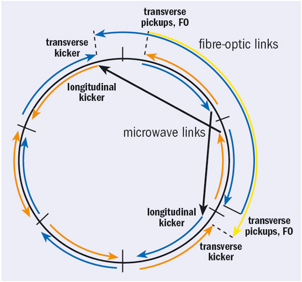
The technique relies on measuring the random fluctuations in the beam shape and size – hence the name “stochastic”, which is derived from statistics and means random. The measurements are made at one point on the accelerator by devices that generate signals proportional to how far the particles are straying from their ideal positions.
At RHIC these devices send the signals via fibre-optic or microwave links to a position ahead of the speeding beam, where electric fields are generated to kick the charged particles back towards their ideal positions. This results in more tightly squeezed (“cooler”) ion bunches. The signals stay ahead of the beam by taking one of two shortcuts: either travelling from one point to another across the circular accelerator or backtracking along the circle to meet the speeding beam roughly halfway round on its next pass.
So far, the team at RHIC has tested stochastic cooling in the longitudinal direction – along the direction of the beam – in one of RHIC’s two rings. Longitudinal cooling compensates for the ion bunches’ tendency to lengthen as they circulate. This improvement has already increased RHIC’s heavy-ion collision rate by 20%. The team has now installed equipment to implement the longitudinal cooling system in the second of RHIC’s rings.
The aim is also to install a system for transverse cooling in one of the beams before 2009. This would allow tests of significantly increased luminosity in gold–gold collisions in RHIC.
This successful demonstration of stochastic cooling provides an alternative way to increase collision rates that is less costly and quicker than other methods considered for RHIC II, electron cooling in particular, which would cost $95 m. Simulations suggest that stochastic cooling, together with other improvements, could increase the luminosity for gold–gold collisions to some 50 × 1026 cm–2s–1, or about 70% of the design goal for RHIC II. The team should be able to complete the system for stochastic cooling with an extra $7 m. According to Steven Vigdor, Brookhaven Associate Laboratory director for nuclear and particle physics, the laboratory hopes to implement the full stochastic cooling system by 2011.
A magnet built originally for the UA1 detector at CERN and later used by the NOMAD experiment has set sail for a new life in Japan. Thirty-five containers carrying 150 pieces departed CERN in the last two weeks of January, with the last components – the large aluminium coils – following in March.
In 2005, at the request of European physicists involved in the international Tokai to Kamioka (T2K) long-baseline neutrino experiment, CERN decided to donate the former UA1 magnet, its coils and other equipment to KEK in Japan. For T2K, which will start in autumn 2009, the Japan Proton Accelerator Research Complex at Tokai will use a 40 GeV proton beam to produce an intense low-energy neutrino beam directed towards the Super-Kamiokande neutrino observatory 300 km away.
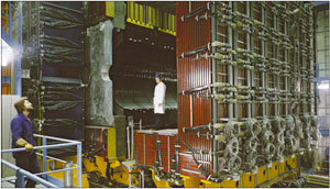
Built in 1979, the UA1 magnet was later given a second lease of life with the NOMAD neutrino-oscillation experiment at CERN. Since NOMAD was dismantled in 2000, the magnet has been stored in the open air, exposed to the elements, at CERN’s Prévessin site. All the parts were cleaned, polished and repainted before shipment to Japan, including a general overhaul in readiness for transport. However, many of the parts could not be transported in one piece, especially by sea, so much of the equipment had to be dismantled before being loaded into containers.
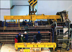
The general overhaul, and other work needed to prepare the parts for shipping, took almost a year. On 14 January, one by one, 35 sea-going containers began their long journey to Tokai, 60 km north of Tokyo. They first travelled by train to Antwerp, from where they were bound for the port of Hitachinaka via Pusan, in South Korea. The final, and largest, component – consisting of the four very fragile coils – was scheduled to leave CERN at the end of March. With a height of 4.75 m, the aluminium coils weigh close to 40 tonnes and have been packaged into two 1.70 m wide consignments for transport as an exceptional lorry load to Basel, then by barge to Rotterdam to set sail for Japan.
On 8 February, the LHCb collaboration succeeded in extracting data from an almost-complete set of detectors. The exercise was an important test run to flag up any problems in the experiment before the next commissioning week in March.
Sixty electronic boards that read out information from the triggered events were used during the tests, collecting data at a frequency of 100 Hz. As not all of the boards have been installed or commissioned yet, this represents only around 20% of the data that the detectors are capable of generating.
There were also indications that cosmic tracks were recorded in the calorimeter system and the outer tracker. Because LHCb is set up with the detectors aligned in vertical planes, it is not easy to record the tracks of cosmic rays. However, there are rare cosmic rays that travel almost horizontally at a rate of a fraction of a hertz through LHCb. The main goal of the commissioning week in March is to collect cosmic events in all detectors together. This will allow an initial alignment in time of all of the components and provide some tracks to be used by the reconstruction and alignment teams.
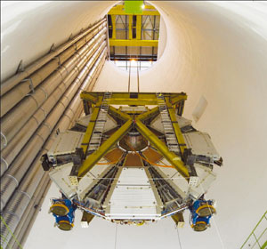
The ATLAS collaboration celebrated lowering the final large piece of the detector into the underground cavern on 29 February. The event marked a major milestone for the muon spectrometer group, as well as the final installation of large detector components below ground.
ATLAS is the world’s largest general-purpose particle detector, measuring 46 m long, 25 m high and 25 m wide. It weighs 7000 tonnes and consists of around 100 million sensors that will measure particles produced in collisions in the LHC. The first major piece was installed in 2003 and since then, many detector elements have journeyed down the 100 m shaft into the cavern. This last piece completes the gigantic puzzle.
Modest in scale compared with the large 25 m diameter muon spectrometer wheels, this last element is one of two pieces known as the “small” wheels, the first having descended into the cavern two weeks earlier. Both small wheels measure 9.3 m in diameter and weigh 100 tonnes, including massive shielding elements. Unlike the large wheels, whose assembly was completed in the cavern, they were assembled on the surface on CERN’s main site and then transported slowly and carefully by road transport across to the ATLAS cavern at Point 1 on the LHC ring.
The whole muon spectrometer system would cover an area equivalent of three football fields, and includes 1.2 million independent electronic channels. The small wheels, which complete the system, are closest to the interaction point in the small-angle region, next to the calorimeter and the two end-caps of the toroid magnet. Each small wheel consists of two discs placed one against the other and slotted together with a central cylindrical component. One wheel provides shielding, which will absorb particles other than muons, while the other acts as the support for the detection chambers. Three of the four different kinds of muon chamber found in ATLAS are fitted onto the small wheels, including trigger chambers and two types of precision chamber – cathode strip chambers and monitored drift tubes – which will allow the muon tracks to be reconstructed with a precision of 10 μm.
The ATLAS muon-spectrometer group comprises 450 physicists from 48 institutions, and includes members from China, France, Germany, Greece, Israel, Italy, Japan, the Netherlands, Russia and the US. They have spent more than a decade developing, planning and constructing the ATLAS muon spectrometer, with the shielding elements constructed in Armenia and Serbia.
With the completion of two major installation projects, nearly all the infrastructure for the ALICE experiment is now in place in the cavern at Point 2 on the LHC ring, near St. Genis-Pouilly in France. Further round the ring, at Point 5 near Cessy, the final large piece has descended into the cavern for the CMS detector, which is the first of its kind to have been constructed above ground before being lowered piece by piece into the cavern below.
In the ALICE cavern, the electromagnetic calorimeter support structure and “mini” space frame – the device for connecting service networks to the inside of the detector – went into position at the end of 2007. At 7 m high and with a weight of 30 tonnes, the calorimeter support structure consists of two austenitic stainless steel “half-shells”, welded and bolted together to give the structure its specially designed curved form. Once the calorimeter is in place, the support will have to bear nearly three times its own weight.
Lowering the structure and positioning it within the ALICE detector constituted major technical challenges for the ALICE installation team, who made numerous preparatory tests, and had to dismantle two walkways to free up the passage into the cavern. They then inserted the structure inside the detector, sliding it in between the face of the magnet and the metal space-frame that bears detector systems in the centre of ALICE. At one point there was a clearance of only a couple of centimetres between the moving structure and the magnet.
Two weeks later, the final big piece of the jigsaw went into place – the “mini” space frame, which resembles a giant socket outlet and weighs 14 tonnes. The device is almost 10 m long and carries all the supply cables for the services required for detector operation (gas, water, electricity, signals). Sitting straight across from the magnet, it connects the inner detector with the outside world.
Around the LHC ring at Point 5, the CMS Collaboration has celebrated the descent of the 15th and final large element of the detector into the experiment’s cavern (see CMS starts underground). Weighing 1430 tonnes and asymmetrical in shape, the end cap designated YE+1 is the largest of the three pieces that form one end of the detector. After the lowering operation, the piece was temporarily stowed as far as possible from the central components to leave room to cable the central tracker (see CMS installs the world’s largest silicon) and install the beam pipe.
Once these components are all in place CMS will be almost ready. All that will remain will be to seal all the components of the detector, and perform the final tests with cosmic rays and the magnet fully powered to 4 T.
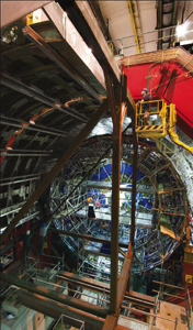
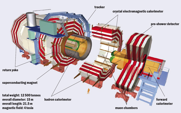
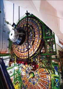
In July 2006, the huge segments of the CMS detector came together for the first time for the Magnet Test and Cosmic Challenge at the experiment’s site near Cessy in France. Within days the commissioning teams were recording data from cosmic rays bending in the 4 T magnetic field as they passed through a “slice” of the overall detector. This contained elements of all four main subdetectors: the particle tracker, the electromagnetic and hadron calorimeters and the muon system (figure 1). Vital steps remained, however, for CMS to be ready for particle collisions in the LHC. These tests in 2006 took place at the surface, using temporary cabling and a temporary electronics barrack, 100 m or so above the LHC ring.
To prepare for the LHC start up, the segments had to be lowered into the cavern one at a time, where the complete system – from services to data delivery – was to be installed, integrated and checked thoroughly in tests with cosmic rays. The first segment – one of the two forward hadron calorimeters (HF) – descended into the CMS cavern at the beginning of November 2006 and a large section of the detector was in its final position little more than a year later, recording cosmic-ray muons through the complete data chain and delivering events to collaborators as far afield as California and China.
This feat marked an achievement, not only in technical terms, but also in human collaboration. The ultimate success of an experiment on the scale of CMS is not only the challenge of building and assembling all the complex pieces; it also involves orchestrating an ensemble of people to ensure the detector’s eventual smooth operation. The in situ operations to collect cosmic rays typically involved crews of up to 60 people from the different subdetectors at CERN, as well as colleagues around the globe who have put the distributed monitoring and analysis system through its paces. The teams worked together, in a relatively short space of time, to solve the majority of problems as they arose – in real time.
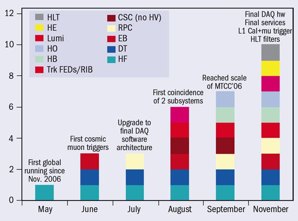
Installation of the readout electronics for the various subdetector systems began in the cavern in early 2007, soon after the arrival of the first large segments. There were sufficient components fully installed by May for commissioning teams to begin a series of “global runs” – over several days at the end of each month – using cosmic rays to trigger the readout. Their aim was to increase functionality and scale with each run, as additional components became available. The complete detector should be ready by May 2008 for the ultimate test in its final configuration with the magnetic field at its nominal value.
At the time of the first global run, on 24–30 May 2007, only one subdetector – half of the forward hadron calorimeter (HF+), which was the first piece to be lowered – was ready to participate (figure 2). It was accompanied by the global trigger, a reduced set of the final central data acquisition (DAQ) hardware installed in the service cavern, and data-quality monitoring (DQM) services to monitor the HF and the trigger. While this represented only a small fraction of the complete CMS detection system, the run marked a major step forward when it recorded the first data with CMS in its final position.
This initial global run confirmed the operation of the HF from the run-control system through to the production global triggers and delivery of data to the storage manager in the cavern. It demonstrated the successful concurrent operation of DQM tasks for the hadron calorimeter and the trigger, and real-time visualization of events by the event display. The chain of hardware and software processes governing the data transfer to the Tier-0 processing centre at CERN’s Computer Centre (the first level of the four-tier Grid-based data distribution system) already worked without problems from this early stage. Moreover, the central DAQ was able to run overnight without interruption.
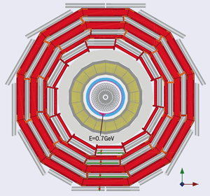
The June global run saw the first real cosmic-muon triggers. By this time, the chambers made of drift tubes (DTs) for tracking muons through the central barrel of CMS were ready to participate. One forward hadron calorimeter (HF) plus a supermodule of the electromagnetic calorimeter (which at the time was being inserted in the CMS barrel) also joined in the run, which proved that the procedures to read out multiple detectors worked smoothly.
July’s run focused more on upgrading the DAQ software towards its final framework and included further subdetectors, in particular the resistive plate chambers (RPCs) in the muon barrel, which are specifically designed to provide additional redundancy to the muon triggers. This marked the successful upgrade to the final DAQ software architecture and integration of the RPC system.
The first coincidence between two subsystems was a major aim for the global run in August. For the first time, the run included parts of the barrel electromagnetic calorimeter (ECAL) with their final cabling, which were timed in to the DT trigger. The regular transfer of the data to the Tier-0 centre and some Tier-1s had now become routine.
By September, the commissioning team was able to exercise the full data chain from front-end readout for all types of subdetector through to Tier-1, Tier-2 and even Tier-3 centres, with data becoming available at the Tier-1 in Fermilab in less than an hour. The latter allowed collaboration members in Fermilab to participate in remote data-monitoring shifts via the Fermilab Remote Operations Centre. On the last day of the run, the team managed to insert a fraction of the readout modules for the tracker (working in emulation mode, given that the actual tracker was not yet installed) into the global run, together with readout for the muon DTs and RPCs – with the different muon detectors all contributing to the global muon trigger.
The scale of the operation was by now comparable to that achieved above ground with the Magnet Test and Cosmic Challenge in the summer of 2006. Moreover, as synchronization of different components for the random arrival times of cosmic-muon events is more complex than for the well timed collisions in the LHC, the ease in synchronizing the different triggers during this run was a good augur for the future.
The global-run campaign resumed again on 26 November. The principal change here was to use a larger portion of the final DAQ hardware on the surface rather than the mini-DAQ system. By this time the participating detector subsystems included all of the HCAL (as well as the luminosity system), four barrel ECAL supermodules, the complete central barrel wheel of muon DTs, and four sectors of RPCs on two of the barrel wheels. For the first time, a significant fraction of the readout for the final detector was taking part. The high-level trigger software unpacked nearly all the data during the run, ran local reconstructions in the muon DTs and ECAL barrel and created event streams enriched with muons pointing to the calorimeters. Prompt reconstruction took place on the Tier-0 processors and performed much of the reconstruction planned for LHC collisions.
To exercise the full data chain, the November run included a prototype tracking system, the “rod-in-a-box” (RIB), which contained six sensor modules of the strip tracking system. The experience in operating the RIB inside CMS provided a head-start for operation using the complete tracker once it is fully installed and cabled in early 2008 (see CMS installs the world’s largest silicon detector). The team also brought the final RPC trigger into operation, synchronizing it with the DT trigger and readout.
Installation in the CMS cavern continued apace, with the final segment – the last disc of the endcaps – lowered on 22 January 2008 (figure 5). The aim is to have sufficient cabling and services to read out more than half of CMS by March, including a large fraction of the tracker.
All seven Tier-1 centres have been involved since December, ranging from the US to Asia. In April, this worldwide collaboration will be exercised further with continuous 24 hour running, during which collaboration members in the remote laboratories will participate in data monitoring and analysis via centres such as the Fermilab ROC, as well as in a new CMS Centre installed in the old PS control room at CERN. By that stage, it will be true to say that the sun never sets on CMS data processing, as the collaboration puts in the final effort for the ultimate global run with the CMS wheels and discs closed and the magnet switched on before the first proton–proton collisions in the LHC.
• The authors are deeply indebted to the tremendous effort of their collaborators in preparing the CMS experiment.
To provide the best experiences, we use technologies like cookies to store and/or access device information. Consenting to these technologies will allow us to process data such as browsing behavior or unique IDs on this site. Not consenting or withdrawing consent, may adversely affect certain features and functions.
Functional
Always active
The technical storage or access is strictly necessary for the legitimate purpose of enabling the use of a specific service explicitly requested by the subscriber or user, or for the sole purpose of carrying out the transmission of a communication over an electronic communications network.
Preferences
The technical storage or access is necessary for the legitimate purpose of storing preferences that are not requested by the subscriber or user.
Statistics
The technical storage or access that is used exclusively for statistical purposes.The technical storage or access that is used exclusively for anonymous statistical purposes. Without a subpoena, voluntary compliance on the part of your Internet Service Provider, or additional records from a third party, information stored or retrieved for this purpose alone cannot usually be used to identify you.
Marketing
The technical storage or access is required to create user profiles to send advertising, or to track the user on a website or across several websites for similar marketing purposes.