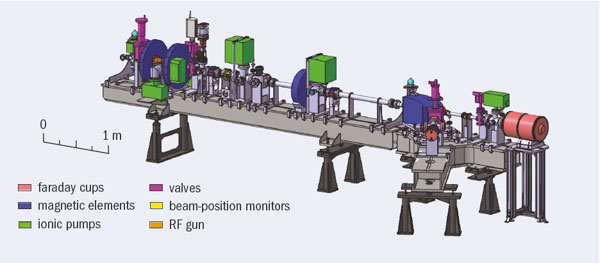
A new linac test facility is under construction at the Laboratoire de l’Accélérateur Linéaire (LAL), Orsay. The primary goal of the accelerator, called PHIL, is for testing photo-injection as part of research and development of advanced RF guns. The size of the machine is modest in comparison with the Photo Injector Test Facility at DESY Zeuthen (PITZ) or the CLIC Test Facility (CTF3) at CERN. However, PHIL will also be used to train students and engineers, and the facility will be open to physics experiments that need low-energy, well-defined electron beams for detector calibration.
As civil engineering was required to reinforce the existing shielding to comply with current radiation safety requirements, the machine has been delayed and is now being constructed in two phases. Phase 0 consists of an RF gun with a copper photocathode, vacuum chambers, pump system, all magnetic elements, a dipole to analyse the energy distribution, and standard instrumentation. It uses a temporary 2.5 cell RF gun fed by a co-axial “doorknob” coupler. This is a copy of the gun constructed by LAL for the ALPHA-X accelerator at the University of Strathclyde in the UK.
For Phase I the laboratory will install a booster to bring the beam energy to 10 MeV and increase the diagnostic facilities. In parallel, a new RF gun will be constructed with a high-efficiency caesium-telluride photocathode prepared in situ in a special vacuum chamber. This will be directly derived from the type IV gun for CTF3.
The photocathodes in the new facility are illuminated by a Nd:YLF picosecond mode-locked laser, which delivers a single pulse at 5 or 10 Hz and is used on the fourth harmonic at 262 nm wavelength. The laser pulse-to-pulse stability is close to 1% for approximately eight hours. The optical path length is approximately 17 m and the laser light is injected at nearly normal incidence on the photocathode. Different spot sizes are obtained by changing the position of the last lens.
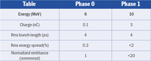
The table above summarizes the technical specifications for PHIL; in addition, the RF frequency is 2.998 MHz and the repetition rate limited to 10 Hz. A dedicated area of 20 m2 for physics experiments has been planned at the downstream end of the accelerator.
All the infrastructure, water cooling, cabling, magnetic elements, RF gun, RF network and RF source are now ready and commissioned for Phase 0, and the control room is available and the software is in the process of completion. The main task remaining is the installation of the laser line optics. RF tests and conditioning should take place just after the summer shut down. The French radiation authority (Autorité de sûreté nucléaire) has authorized LAL to produce a first test beam run and, after a radiation control, the laboratory should obtain the permanent authorization for routine operations before the end of the year.
JINR, Dubna, was host to the latest in the general meetings of the Global Design Effort (GDE) for a future International Linear Collider (ILC). The workshop on ILC Conventional Facilities and Siting (CFS) took place between 4–7 June 2008. It provided the opportunity for GDE members to take a look at the potential site near Dubna, first proposed in 2006.
The meeting focused on issues surrounding conventional facilities, such as water cooling and other cost drivers, which in turn depend on the eventual siting of a high-energy linear collider. (The conventional facilities account for about a third of the total estimated cost.) Parallel sessions at the workshop aimed at understanding the potential impact on the cost of various solutions, both for the current ILC Reference Design and alternative scenarios. The workshop also included discussions of CFS issues for a Compact Linear Collider, to try and identify common cost-effective solutions for both machines.
In preparing the reference design report issued in 2007, the GDE considered a deep site, about 100 m below ground. To proceed with the reference design, the GDE had asked the regional subgroups for “sample sites” in the three regions: the Americas, Asia and Europe; all three were deep. By contrast, the proposal submitted for the GDE’s consideration by Grigory Shirkov, ILC project leader and chief engineer at JINR, is for a shallow site, requiring the construction of only one tunnel instead of two. This plan, which resulted from the joint discussions between JINR and the State Specialized Design Institute in Moscow, has a tunnel 20 m below ground in a thick layer of dry soil (loam). The collider infrastructure can be installed at or near the surface, avoiding the need for a second service tunnel. The region is seismically stable within almost 50 km of the site proposed for the collider and is practically uninhabited. The participants of the meeting had a chance to look at the suggested area from a helicopter, offered by the governor of the Moscow region, Boris Gromov.
While at Dubna, GDE members also met with representatives of the Russian State Project Institute, Moscow, which has a long history of designing and constructing nuclear power stations, nuclear centres and scientific accelerator centres, including those at JINR and at the Institute for High Energy Physics in Protvino. Discussions are now under way on work towards more detailed studies, including drilling a 1.6 m borehole near the proposed location of the interaction region. In addition to the Dubna site, the GDE plans to study other possible shallow sites, for example in a desert, and to study further the engineering options in deep sites, with a view to minimizing costs.
Champagne-bottle corks popped early on the morning of 20 July, as researchers at the Institute of High Energy Physics (IHEP) in Beijing celebrated the observation of the first particle collisions in the upgraded Beijing Electron Positron Collider (BEPC II) and the new Beijing Spectrometer, BES III. Although BEPC II and BE III had already been carefully tested separately, this was the first time that they had operated together.
The first collisions, occurring late the previous afternoon, represent a new milestone for the project, which was nearly four years in planning and took another four and half years to construct. When fully operational, the BEPC II/BES III complex will be the world’s premier facility for studying properties of charmed mesons and τ leptons.
BEPC II is a major upgrade of IHEP’s previous e+e– collider, BEPC. The major change has been the addition of a second ring of magnets that allows the electron and positron beams to be stored separately. In the original machine, the electrons and positrons shared the same vacuum tube in a single ring of magnets, which limited the intensities of each beam and, therefore, the luminosity. The two separate rings of BEPC II will allow 93 bunches of electrons to collide with 93 bunches of positrons, with an expected increase in collision rate of more than 100-fold. Other improvements include a more powerful injection linac for electrons and positrons, and extensive use of superconducting technology, both for the RF-accelerating cavities and for the magnetic final focusing of the stored beams as they enter the interaction region.
The linac upgrade was finished in late 2004 and quickly reached its design goals. With the exception of the conventional focusing magnets in the interaction region, construction of the double rings was completed in October 2006. Beams were first stored the following month and synchrotron radiation running commenced soon after. The first collisions using conventional final-focus magnets were produced in March 2007 and collisions with the superconducting final-focus magnets followed in November, achieving 500 mA on 500 mA beam–beam collisions with a luminosity higher than 1 × 1032 cm–2s–1.
The assembly of the BES III detector was completed in January 2008 and it was moved into the interaction region in early May. A major improvement in this detector over its predecessor, BES II, is the huge superconducting solenoid magnet with a central field of 1 T. This magnet – the most powerful magnet in China – was built at IHEP by the laboratory’s research staff. Together with the new helium gas-based tracking chamber, it provides a factor of five improvement in charged-particle momentum resolution over BES II. In addition, BES III contains an array of 6240 caesium iodide crystals to measure the energies of high-energy electrons and gamma rays. The crystal calorimeter provides more than a factor of 10 improvement in the precision of measurements of electromagnetic shower energies.
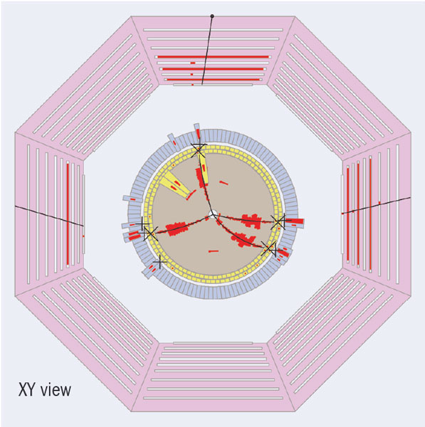
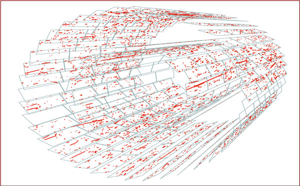
To handle the huge, LHC-scale data rates expected when BES III operates at the J/ψ peak, the team has developed a specialized state-of-the-art, high-speed data-communication system. The figure shows an event display of the first candidate charmed-meson pair event in BES III, demonstrating that the detector and its associated software are performing well.
During the Saturday-night/Sunday-morning test run, operation of BEPC II proved stable, with a luminosity that hovered around 1030 cm–2s–1, about a factor of 1000 times below the project’s ultimate design goal of 1033 cm–2s–1. This was partly because the operators used a 1-bunch-on-1-bunch collision mode to limit the intensity of the beam currents, avoiding possible damage to the sensitive detection elements of the BES III spectrometer, while the team also made sure that everything worked as expected. The next day, 20-bunch-on-20-bunch operation was quickly established, with a much higher luminosity. So far the beam-associated radiation background in the detector is manageable, even with the increased currents. During the coming months the intensity of the beams will be gradually increased while BES III’s 2000 detection elements will be carefully adjusted and calibrated. When this process is completed, sometime in the early autumn, the BES III research programme will begin.
• BES III is run by a team from China, Hong Kong, Germany, Japan, Russia and the US.
As the cool-down phase of commissioning the LHC came towards a successful conclusion at the beginning of August, CERN announced that the first attempt to circulate a beam in the LHC will be made on 10 September. The announcement was soon followed by the first sight of protons – albeit a small number – in the LHC during tests to synchronize the LHC’s clockwise beam transfer system.
The LHC is unlike any other particle collider, being the first to have two beams of particles travelling in opposite directions in separate channels within the same magnetic structure, and it is the first to operate with superfluid helium at 1.9 K. It truly is its own prototype.
Starting up a machine like this is not as simple as flipping a switch. Commissioning is a long process that starts with the cooling down of each of the machine’s eight sectors. This is followed by electrical testing of the 1600 superconducting magnet systems, and their individual powering to nominal operating current. Once these steps are completed, the powering together of all the circuits of each sector can begin. Only then can the eight independent sectors be powered up in unison to operate as a single machine.
There are around 1400 tests of varying complexity to be performed on each sector after it reaches 1.9 K. These include: electrical quality assurance to check that all the wiring is in place after the magnets have contracted during cool down; individual testing of protection systems; and power testing. These tests are done by the Operations Group together with teams of equipment experts from the Accelerators and Beams, Accelerator Technology and Technical Support Departments. A dedicated hardware commissioning team coordinates this effort.
After all these tests have been completed, the sectors are then handed over to the Operations Group to commence “dry runs”, where the machine is run as it would be with the beam. There are also safety tests that must be done before the beam can circulate, to prevent people from being in the tunnel at the same time as the beam.
By the end of July, this work was approaching completion, with the whole machine fully loaded with 130 tonnes of liquid helium for the first time, and the final commissioning of the hardware progressing apace. All eight sectors were at or close to the operating temperature of 1.9 K required to reach the high magnetic-field strengths necessary to bend the beams at 7 TeV.
The next phase in the process is the synchronization of the LHC with the SPS accelerator, which forms the last link in the LHC’s injector chain. Timing between the two machines has to be accurate to within a fraction of a nanosecond. The synchronization of the LHC’s clockwise beam-transfer system was successfully achieved on the weekend beginning 8 August, when a single bunch of protons was taken down the transfer line from the SPS accelerator to the LHC. After a period of optimization, one bunch was kicked up from the transfer line into the LHC beam pipe and steered about 3 km around the LHC itself on the first attempt. The following day, the test was repeated several times to optimize the transfer before the Operations Group handed the machine back for hardware commissioning to resume. The anti-clockwise synchronization systems will be tested over the weekend of 22 August.
These tests will prepare the LHC for the first circulating beam on 10 September at the injection energy of 450 GeV. Once stable circulating beams have been established they will be brought into collision, and the final step will be to commission the LHC’s acceleration system to boost the energy to 5 TeV per beam – the target energy for 2008. The decision to run the LHC at 5 TeV rather than 7 TeV this year is related to the need to re-train the superconducting magnets in the tunnel to reach the nominal field after some “de-training” occurred during transport and installation.
The ALICE experiment at the LHC is optimized for the study of heavy-ion collisions to investigate the behaviour of strongly interacting matter under extreme conditions of compression and heat. The interpretation of the data will rely on a systematic comparison of measurements with the same observables in proton–proton (pp) and proton–nucleus (pA) collisions, as well as in collisions of lighter ions under the same experimental conditions. The tracking and particle-identification capabilities of ALICE are designed to allow a precise study of these benchmarking processes and to perform efficiently in the particularly demanding conditions of the heavy-ion programme.
A key characteristic of heavy-ion collisions at the LHC energy is the high number of particles produced per event, more than two orders of magnitude higher than in a typical proton–proton collision in the central region. The design of ALICE is optimized for a charged particle multiplicity of around 4000 and has been tested with simulations up to double this number. The use of mainly 3D hit information with many points (up to 150) in a moderate magnetic field of 0.5 T makes the tracking capability particularly safe and robust.
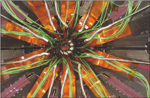
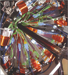
Tracking in the central barrel of ALICE is divided into a six-layer silicon-vertex detector, which forms the inner tracking system (ITS) surrounding the beam pipe, and the time-projection chamber (TPC). The main functions of the ITS are the localization of the primary vertex (with a resolution better than 100 μm), the reconstruction of the secondary vertices from the decays of D and B mesons and hyperons, the tracking and identification of particles with momentum below 200 MeV/c, and improving the momentum and angle resolution for particles reconstructed by the TPC. The silicon pixel detector (SPD) forms the innermost two layers of the ITS, which is surrounded by two layers of drift detectors and two layers of double-sided microstrips. The drift and microstrip layers are equipped with analogue readout for independent particle identification via energy loss, dE/dx, in the non-relativistic region, thus providing the ITS with stand-alone capability as a spectrometer for particles with low transverse momentum, pt.
The SPD will operate in a region where the track density could be as high as 50 tracks/cm2. It has a key role in the determination of the position of the primary vertex and in the measurement of the impact parameter of secondary tracks originating from the weak decays of strange, charm and beauty particles. The active length of the two SPD layers is about 28 cm, with an acceptance coverage in pseudorapidity of η = ±2.0 for the inner layer and η = ±1.4 for the outer one, located around the beam pipe at average distances of 39 mm and 76 mm from the beam axis, respectively. The smallest clearance between the inner layer and the wall of the beam pipe – an 800 μm thick beryllium cylinder with an outer diameter of 59.6 mm – is less than 5 mm.
A distinctive feature of the SPD is the reduced amount of material seen by traversing particles. The resolutions in momentum and impact parameter for low-momentum particles are dominated by multiple scattering in the material of the detector. To keep the pt cutoff as low as possible, the SPD design uses several specific solutions to minimize the amount of material in the active volume. The result is that a straight track perpendicular to the detector surface traverses on average an amount of material per layer corresponding to about only 1% of a radiation length.
Another important consideration is the amount of radiation to which the SPD will be exposed during LHC operation. For 10 years of a standard running scenario, the integrated radiation levels of total dose and fluence on the inner layer are estimated to be 2.7 kGy and 3×10¹² n/cm2. (1 MeV neutron equivalent), respectively. While this is lower than for other LHC detectors, the on-detector ASICs for the SPD have nevertheless been implemented in radiation-hard, deep-submicron technology, like the other more demanding cases at the LHC. The relatively modest radiation levels allow the detector to operate at ambient temperature without the risk of significant long-term degradation of the sensor characteristics. The total power dissipation in the on-detector electronics is around 1.35 kW. This is not high; however, because the mass of the detector is low, if the cooling system were to fail, the temperature would rise at a rate of about 1 °C/s. For this reason, the SPD has fast-acting, redundant temperature safety systems.
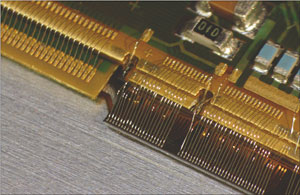
The basic components of the SPD are hybrid silicon pixels in the form of a two-dimensional matrix of reverse-biased silicon detector diodes. Each diode is connected through a conductive solder bump to a contact on a readout chip that corresponds to the input of a readout cell. The readout is binary: for each cell, a threshold applied to the pre-amplified and shaped signal produces a change in the digital output level when the signal is above a set threshold.
The SPD contains 1200 readout pixel chips and a total of 107 cells. The detector element is called a ladder, which consists of a silicon-sensor matrix bump-bonded to five readout pixel chips. The ladder sensor matrix contains 256×160 cells measuring 50 μm (rφ) by 425 μm (z), with longer sensor cells in the boundary region to assure coverage between readout chips. The ladders are attached in pairs to an interconnect (the pixel bus) that carries data/control bus lines and power/ground planes; a multi-chip module (MCM), located at one end of the pixel bus, controls the front-end electronics and is connected to the off-detector readout system via optical-fibre links.
Two ladders, the pixel bus and the MCM together form the basic detector module, known as a “half stave”. Two half staves, attached head-to-head along the z direction to a carbon-fibre support sector, with the MCMs at the two ends, form a stave. Each sector of the SPD supports six staves; two on the inner layer and four on the outer layer, and ten sectors mounted together in enclosed geometry around the beam pipe form the full two-layer barrel. Each half stave generates an 800 Mb/s output serial-data stream. The 120 half staves that form the SPD are all read in parallel, with full detector readout taking around 256 μs.
Although small in physical size, the SPD is packed with advanced and novel technical solutions, including the following few examples. To obtain the lowest material budget, the pixel ASIC wafers were thinned down to 150 μm after deposition of the solder bumps, which are about 20 μm in diameter. They were then diced and the die flip-chip bonded to 200 μm thick silicon sensors to form a ladder. This whole process was challenging and required specific developments by the industrial partners (VTT in Finland, Canberra in Belgium and ITC-irst, now FBK, in Italy).
Material budget considerations also led to the development of the pixel bus, a high-density aluminium/polyimide multi-layer flex. This technology, in which aluminium is used in place of copper, is not an industry standard and was made possible by the expertise available in the TS-DEM workshop at CERN. The optical transceiver module (one on each MCM), housed in a silicon package barely 2 mm thick, is a custom development by the same company that produced the optical links for the two larger LHC detectors.
The cooling system is of the evaporative type based on C4F10 and has required a specific system development. The sectors are equipped with cooling tubes and capillaries embedded in the carbon-fibre support sector, running underneath the staves (one per stave). The cooling tubes are made from a corrosion-free metal alloy (Phynox) with walls only 40 μm thick.
A unique feature of the SPD is its capability to generate a prompt trigger based on an internal Fast-OR. Each pixel chip provides a Fast-OR digital pulse when one or more of the pixels in the matrix are hit. This was originally included for self-test purposes, but it became clear that it could be adapted to generate a multiplicity trigger with a considerable interest for physics.
The Fast-OR signals of the 10 chips on each of the 120 half staves are transmitted every 100 ns on the 120 optical links that are also used for the data readout. They are processed in a separate processor unit according to a variety of predefined trigger algorithms to generate a signal that can contribute to the Level 0 (L0) trigger decision in the ALICE central trigger processor (CTP). Simulations have shown that using the Fast-OR information in the L0-trigger decision significantly improves background rejection in proton–proton interactions and event selection in heavy-ions runs.
The pixel-trigger signal generated by the Fast-OR processor must reach the CTP within about 800 ns of the interaction to meet the latency requirements of the L0-trigger electronics. The design has brilliantly met this challenging requirement for the trigger processor in tests and the full system is now being commissioned in ALICE with cosmic rays.
A major challenge for the LHC collaborations has been to bring together components and subsystems developed at institutes and production laboratories in different countries and locations. The SPD is no exception. The laboratories that took part in the design, development and construction of the SPD are: CERN, INFN and the University and Politecnico of Bari, INFN and the University of Catania, INFN/Laboratori Nazionali di Legnaro, INFN and the University of Padova, INFN and the University of Salerno, INFN and the University of Udine, and the Slovak Academy of Sciences of Košice.
The final integration of the SPD took place at CERN’s Departmental Silicon Facility, which was equipped to test the individual sectors and for the integration and pre-commissioning of the full detector, including the cooling plant and the full-scale configuration of power supplies and services. This strategy proved invaluable for debugging the system before installation in the experimental area.
In June 2007 the SPD was finally installed in the ALICE experimental area at Point 2 in the LHC ring, with connection to services possible in November, when the mini-frame carrying service interfaces was put in place.
Commissioning of the SPD started in January 2008 with the aim of being fully ready by the time that the LHC delivers the first proton–proton collisions, scheduled for later this summer. Indeed, the SPD is one of the ALICE sub-detectors to contribute to the measurement of the charged-particle multiplicity, which is the common objective of “day-one” studies for all of the LHC experiments.
Since May the SPD has been collecting cosmic data triggered by the Fast-OR trigger signal produced by the SPD itself. The events are selected by requiring at least one hit in the outer layer of the top half-barrel in coincidence with at least one hit in the outer layer of the bottom half-barrel. These data samples are being used for a preliminary alignment of the SPD components. More recently the same signal is being used to trigger other ALICE subdetectors: first the other two ITS systems – the drift and double-sided microstrip detectors – and then the TPC, thus exercising the combined TPC-plus-ITS tracking.
On the evening of 15 June, while preparing the detector for the cosmic run, the triggered events from the SPD showed a puzzling pattern never seen before. It took a while for the team working in the control room to realize that the SPD was observing one of the first signs of life of the LHC at Point 2: muon tracks produced in the beam dump during the injection test in transfer line TI 2.
• It is unfortunately impossible in this short article to give the well deserved credit to all of those who have deployed a relentless effort over nearly a decade to lead to completion this complex and exciting detector successfully to completion.
The Beam Test Facility (BTF) is part of the DAΦNE Φ-factory complex, the most recent of the electron–positron colliders in the long history of the INFN Laboratori Nazionali di Frascati (LNF). The facility features a high-intensity linac that provides electrons and positrons up to 750 MeV and 550 MeV respectively, a damping ring to improve injection efficiency and two main rings designed for the abundant production of K mesons coming from the decay of the Φ resonance at 1.02 GeV (Mazzitelli et al. 2003). The main research goal is to study matter–antimatter asymmetry and the interactions of “s” quarks, but K mesons are also useful tools in nuclear and atomic physics.
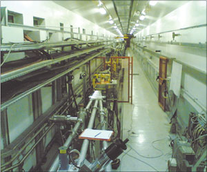
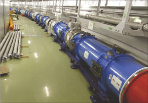
Before the high-intensity electron or positron beam pulses produced by the 60 m long linac are injected into the double storage ring, they can be extracted to a transfer line that is dedicated to the calibration and ageing of particle detectors, the characterization and calibration of beam diagnostics, and the study of low-energy electromagnetic interactions (figure 1). Here, the number of particles can be reduced to a single electron or positron per pulse by means of a variable thickness copper target. The particle momentum is then selected, with an accuracy better than 1%, using a dipole magnet and a set of tungsten collimators. The energy range is typically 25–500 MeV, and up to 49 pulses per second can be extracted (20 ms repetition time), with a bunch length of 10 or 1 ns. When not operating in conjunction with the collider, the linac’s maximum beam energy can be raised to 750 MeV (for electrons) and the intensity increased to a maximum of 1010 particles per second, limited by radiation safety.
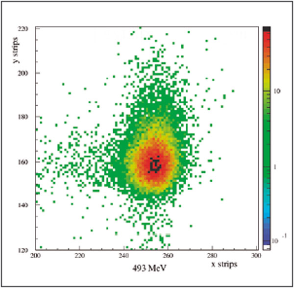
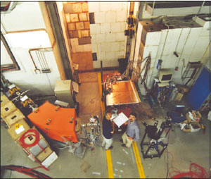
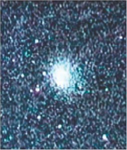
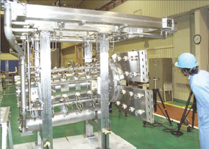
When operating in low-intensity mode, particles are selected from the secondary showers emerging from the target, so either electron or positron beams can be chosen. The final intensity can easily be tuned (by adjusting the tungsten collimators) over a range of several orders of magnitude – from 104–105 particles per pulse, down to a single particle (Poisson distributed). An optical system of four quadrupoles along the BTF transfer line allows the transverse distribution of the beam to be tuned. A typical beam spot of 2×2 mm2. transverse section (1σ profile), with an angular divergence of about 2 mrad, is produced at 500 MeV in single-particle mode (figure 2). Two different beamlines are available, depending on the configuration of the final dipole magnet in the experimental hall (figure 3). When needed, the full-intensity beam can be extracted to the BTF area by removing the copper target from the beamline.
The commissioning of the transfer line, the two BTF exit lines and all the diagnostic devices needed for a reliable operation of a test-beam facility was completed in autumn 2002. The facility has since hosted tens of groups from all over Europe, who have run a variety of experiments and tests with electron and positron beams.
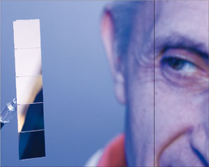
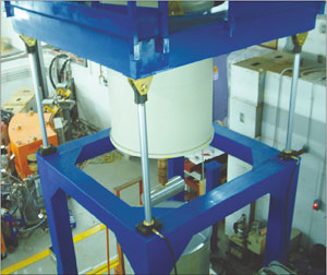
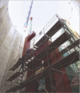
The applications of the BTF beam – with its intensity and energy range, good spatial and excellent timing properties – are extremely wide ranging. Typical uses of the facility in its single-electron mode of operation include testing the ring-imaging Cherenkov system for the LHCb experiment at CERN’s LHC and using electrons at 500 MeV to make highly accurate measurements of the efficiency of OPAL lead glass used in the NA62 experiment at the SPS. A more unusual investigation concerned the thermoacoustic detection of particles by the type of ultracryogenic resonant antenna used for gravitational-wave detection. Such antennae are sensitive enough to detect the impact of cosmic rays, and indeed the tests could observe the vibration occurring when the full force of the high-intensity BTF beam struck the antenna (figure 4 and 5).
An important upgrade of the BTF line was completed in 2005, with the installation of dedicated devices for the production of a beam of tagged photons. To intercept the BTF beam with a small, but not negligible, probability of emitting a bremsstrahlung photon, an active target made of four layers of single-sided silicon microstrip detector planes can now be inserted just before the last dipole magnet that selects one of the two exit lines. In this case the electron is not transported through the dipole but instead hits the inner wall of the vacuum pipe inside the magnet. Its energy is then detected by a series of silicon microstrip detector modules installed outside the beam-pipe, thus allowing the reconstruction of its bending radius. Combined with the measurement of position and angle in the active target, this yields the energy of the radiated photon with a resolution of 7% in the 200–500 MeV range, at a typical production rate of 0.5 Hz. This photon-tagging system has been used successfully for the calibration of the scientific payload (in particular the tungsten/silicon detector minicalorimeter) of the gamma-ray astronomy satellite AGILE, launched by the Italian Space Agency in summer 2007 (figure 6).
Since March 2007 the duty factor of the facility has been improved from 40% up to 90% of the operation time of DAΦNE, thanks to the installation of a new dedicated pulsed-dipole magnet, designed, in collaboration with Maurizio Incurvati and Claudio Sanelli at INFN-LNF, by CERN (Maccaferri and Chiusano 2006). This is capable of driving any of the 50 linac pulses per second to either the accumulator ring or the BTF transfer line. The BTF, operated by the Frascati Accelerator Division staff, typically provides beam for an average period of 250 days a year.
The BTF facility is already equipped with instrumentation and diagnostics capable of covering the entire energy and intensity range. It is also continuously being improved to satisfy the growing interest of the broad scientific community that it serves. The support and collaboration of the users is crucial for better operation and development of the facility. Many improvements of the BTF diagnostic tools have been introduced in collaboration with hosted groups. The requests and proposals made by the user community are important in pushing exploration towards new operating schemes and new possibilities, including projects for the production of a low-intensity neutron beam and R&D studies for high-precision diagnostics at high intensities, all of which are under way.
T2K is a second-generation, long-baseline, neutrino-oscillation experiment that will study the nature of neutrinos. A neutrino beam generated by the high-intensity proton accelerator of the Japan Proton Accelerator Complex (J-PARC) at Tokai will travel 295 km to the 50 kilotonne water Cherenkov detector, Super-Kamiokande, which is located about 1000 m underground in the Kamioka mine.
The J-PARC neutrino facility will follow the standard route for making a neutrino beam. This begins with an intense proton beam that strikes an appropriate target to create many secondary particles, including pions and kaons, which in turn decay to muons and the desired muon-neutrinos. The secondary particles pass through a decay volume followed by an absorber, or beam dump, which removes all but the muons and neutrinos from the beam. A further absorber – the rock in the Earth between the beam dump and the detector – removes the muons to leave only the neutrinos.
At J-PARC the primary beam line will consist of superconducting combined-function magnets for the arc section, with normal conducting magnets for fast extraction and the final focus. The target will form part of the secondary beam line, which will also contain the magnetic horn system to focus the pions and kaons into a beam, the decay volume, and the beam dump and muon monitors. The horn system being used consists of three horns, the first being combined with the target system. In addition, buildings for services such as power supplies and cooling water systems for the beam lines are under construction, as well as the building and underground pit for the near neutrino detector, ND280, which will monitor the neutrinos.
Work on the primary beam line is making good progress. The normal conducting magnets are all in place, and the installation of cabling and piping is under way. In the arc section, 12 of the 14 doublets of superconducting magnets have been installed, together with beam position monitors. The survey and alignment took place in April, with remaining work carried out after the commissioning of the main proton ring at 3 GeV. This saw the successful injection of 3 GeV protons from the rapid cycling proton synchrotron into the main ring on 22 May. Commissioning to 30 GeV will take place from December 2008 to February 2009, and the commissioning of the fast extraction for the neutrino beam should start in April 2009.
For the neutrino beam line, both the helium vessel for the decay volume and the target station (where the target and horn system will be installed) have been completed. Civil engineering around them continues on the target station building and the pit for the beam dump and muon monitors. The installation of the neutrino equipment into the target station should begin in July. The complete arrangement for the third horn was assembled at KEK in Tsukuba to debug the remote handling system that will be used for installation and maintenance. Tests on the operation of this horn began in April, while tests on assembling the target system and the first horn are scheduled for completion by July.
The beam dump consists of 14 core modules composed of graphite blocks and aluminium cooling plates. The modules were completed by the beginning of April, and by November they should be assembled together to form the beam dump, prior to installation in the beam-dump pit. Construction of the muon monitors is also under way and they are scheduled for testing with beam in July.
The pit for the neutrino monitor became available in April, so installation work could begin on the large magnet for the ND280 near detector, which is being assembled below ground before construction work begins on the surface building. The magnet has been donated by CERN, having been used in the UA1 experiment, for which it was built, and subsequently in the NOMAD neutrino experiment. It consists of 16 C-shaped yoke pieces, together with two carriages for the yokes, rails and other components. For the journey to Japan the yokes were disassembled into 32 short pieces and 16 long pieces, so as to fit into standard containers.
The various pieces travelled to Japan in three shipments, mainly by sea. The first and second shipments were for the yokes, carriages and jigs etc, while the third contained the delicate coils. The first shipment arrived at Japan’s Hitachinaka port on 18 March, bringing 24 short yoke pieces in 12 containers each 20 ft long, together with the two carriages each in a 40 ft container, and a third 40 ft container with items such as jigs. The two carriages, jigs and other items were transported from the port to J-PARC on 28 March in readiness for installing the magnet in the neutrino monitor pit. The task of unloading the 24 short yoke pieces at the area began on 1 April and on 3–4 April they were moved to the neutrino monitor area.
The second shipment arrived at the port on 10 April, bringing the remaining eight short yoke pieces and the 16 long yoke pieces. The short yoke pieces were taken into the neutrino monitor area on 19 April, and by the end of the month, the mobile crane had unloaded the long yoke pieces and carried them to the area, ready for re-assembling the short and long pieces into the16 yokes prior to installation in the pit. The coils, in the third and last shipment, were due to be delivered to the neutrino monitor area in the middle of June, for subsequent installation in the magnet yoke.
The survey to put reference lines on the floor of the neutrino monitor pit was carried out soon after the site became available, and by 14 April the rails for the yoke carriages were in position. The carriages were then lowered into the pit and mounted on the rails. The system for aligning the yokes was also set up, ready for when the yokes are installed on the carriages.
The 16 full yokes are being assembled at a rate of one per day. After they are all assembled, they will be lowered into the pit and mounted on the carriages using the alignment system. The plan is to complete installation of the yokes by the beginning of June. By this time, the coils should have been delivered from the port to the neutrino monitor area, in time for installation into the magnet yokes. Complete installation of the magnet in the neutrino monitor pit is scheduled for the end of June. The complete J-PARC neutrino beam facility and the near detector ND280 should then be ready by March 2009 so that the T2K experiment can start in April 2009.
• The T2K collaboration thanks the CERN management and European colleagues for their generosity in donating the UA1 magnet and their hard work in its preparation at CERN and J-PARC.
Exploiting the full potential of physics at the LHC, which includes R&D that is focused on upgrading luminosity, is the highest priority of the European Strategy for Particle Physics, which was adopted unanimously by the CERN Council in July 2006. The first LHC physics approaches ever nearer as the LHC hardware commissioning makes steady progress towards providing beams to the experiments later this year (Protons knock on the LHC’s door). Meanwhile, accelerator and detector experts are already looking farther into the future. They have begun preparatory work for the luminosity upgrade, known as the Super-LHC (SLHC), which was announced in April with an event at CERN to “kick-off” R&D (see ‘April event kicks off for the SLHC’, below).
The current LHC configuration is set up to produce proton–proton collisions at a centre-of-mass energy of 14 TeV and a luminosity of up to 1034 cm–2s–1. It will also provide high-energy lead–lead ion collisions at a centre-of-mass energy as high as 1.15 PeV (1150 TeV). The SLHC project, however, aims for a tenfold increase in luminosity for 14 TeV proton–proton collisions, achieved through the successive implementation of several new elements and technical improvements that are scheduled for 2012–2017. These include the major replacement of several accelerators in the LHC proton-injector chain, upgrades of the LHC-interaction regions and enhancements to the general-purpose experiments ATLAS and CMS.
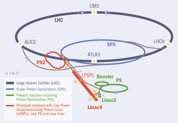
Understanding how to improve the luminosity yield of the LHC has required careful scrutiny of the whole proton-injection and accelerator chain to seek out bottlenecks, inherent weaknesses and reliability problems. The findings are that more luminosity gain can be obtained from improvements to the injector chain than from changes in the LHC machine itself. This is no surprise, considering that some elements of the injector chain date from as early as 1959, when no one would even have dreamed of a superconducting accelerator the size of the LHC. In the current chain, protons pass successively from the source through Linac2, the Booster, the PS and the SPS before final injection into the LHC. The SLHC plans propose a future sequence of Linac4, the Low-Power Superconducting Proton Linac (LPSPL), PS2 (a new machine) and the SPS. Figure 1 shows both present and future schemes, while the aerial view shows more directly how the injectors will be positioned on the site at CERN.
The first bottleneck in the present layout occurs with the injection of proton bunches from Linac2 into the Booster. Protons are injected at 50 MeV by a multiturn injection process that inherently dilutes the beam brightness (the current within a given emittance). Much can be gained from using H– particles in the linac followed by injection in the Booster using a charge-exchange technique that removes excess electrons. This method avoids a dilution of beam brightness and directly translates into a luminosity increase in the LHC. Capturing and accelerating the now more brilliant beam requires an energy increase in the linac, thus reducing the beam self-repulsion in the Booster. This justifies the present 50 MeV proton linac (Linac2) being replaced by a new 160 MeV linac (Linac4) operated with H– ions. Plans for Linac4 are well advanced and its construction will begin soon, aiming for commissioning by 2012. This will result in a doubling of peak LHC luminosity.
Next in the present injector chain are the Booster and the PS, both of which suffer from inherent intensity limitations and reliability problems after many years of service. These both call for new injectors designed for the needs of the LHC, which also take into account potential future projects like a neutrino factory or a next-generation nuclear-isotope facility. Current plans concentrate on extending the energy of Linac4 to several giga-electron-volts (i.e. the LPSPL) and a new 50 GeV synchrotron called PS2, resulting in a higher performance – in particular, an increased SPS injection energy of 50 GeV and another doubling of the proton flux. Both machines are now entering the R&D and design-optimization stage, aiming for a decision on construction by 2011. The building of these new injectors can take place in parallel with operation of the LHC, with a changeover expected in 2017 after an extended shutdown.
In the LHC itself, major elements of the interaction regions in the two high-luminosity insertions can be replaced to give yet another luminosity gain of a factor of two. In particular, new focusing triplets based on Nb-Ti superconducting technology are forseen. Compared to the present systems they will have a larger aperture and will allow the beam size at the interaction point to be reduced. The new triplets will require parallel improvements in the LHC collimation system and the separation elements near the interaction regions, to be implemented before the 2013 physics run.
The ATLAS and CMS experiments will also require upgrades to increase their sensitivity limits in the presence of the higher interaction rates and increased radiation levels. At the SLHC, “pile-up” will amount to as many as 400 events per bunch crossing. This requires adapting trigger and data-acquisition schemes, as well as the complete replacement of the central tracking detectors. The new trackers will have finer granularity and an increased radiation hardness, while particular emphasis will be placed on minimizing their material budget. The forward muon regions will need major modifications, complemented by new beam-pipe elements and reinforced shielding.
While all of these technical developments towards the SLHC take place, LHC operation will continue uninterrupted and the LHC experiments will pursue their quest for new discoveries in the head-on collisions of protons and ions of extraordinarily high energy. In particular, these are expected to increase our knowledge of the origin of mass, the formation of matter, matter–antimatter asymmetries and issues such as extra dimensions of space, microscopic black holes and dark matter in the universe. Profiting from the successive luminosity increases, the SLHC will undoubtedly allow for further probing of phenomena first detected at the LHC. It will also provide better access to the detection of low-rate phenomena that will be inaccessible to the LHC, and will push the sensitivity limits for new physics processes to higher mass-scales.
Many R&D activities for the SLHC are now starting, thanks to several national funding sources, additional funding made available to CERN from its member states, and funding from the European Commission. The corresponding collaboration frameworks with worldwide partners are being established for the accelerators and for the experiments.
• April event kicks off for the SLHC
A public “kick-off” event, marking the start of SLHC developments, was held at CERN on 9 April. The aim was to inform a wide audience about the SLHC project. In a packed auditorium, the event began with a speech by CERN’s chief scientific officer, Jos Engelen. He emphasized the importance of developments towards the SLHC within the European particle physics strategy and commended the position taken up by SLHC activities within CERN’s overall programme. These will maintain the thrust of the numerous innovations accomplished for the design and implementation of the LHC, while working towards full exploitation of the LHC’s new physics. Engelen also reported on the role taken up by the LHC Committee in peer reviewing the R&D for the upgrade, and he encouraged the audience to submit their proposals.
The event continued with three overview talks. Michelangelo Mangano of CERN’s Theory Unit gave a talk on the present views on the physics potential of the SLHC – physics options that will become more refined as the LHC begins to reveal its secrets. Lyn Evans, LHC project leader, outlined the accelerator upgrade plans and associated timescales. Jordan Nash of Imperial College reported on the upgrade plans of both the ATLAS and CMS experiments. The event concluded with lively discussions on the impact of the announced gradual luminosity increases on the present physics, operation and upgrade plans of these experiments.
The study of rare isotopes with proton and neutron compositions far outside the “valley of stability” provides critical tests of nuclear models. Several facilities around the world produce such isotopes by directing energetic beams of nuclei into solid targets. Now researchers are exploring ways to extend their investigations by collecting the rare isotopes and forming them into new reaccelerated beams.
There are two basic approaches to producing rare isotopes, which differ in the thickness of the target employed. Isotope separation on line (ISOL), developed some 40 years ago at CERN’s ISOLDE facility, uses a target that is thick enough for the nuclei to come to a stop within it. The isotopes can then be extracted, but this is a slow process – a problem for short-lived isotopes. In addition, each new element requires dedicated development work and some elements, such as refractory metals, are difficult or impossible to obtain.
Nonetheless, facilities such as ISOLDE, the Isotope Separator and Accelerator (ISAC) at TRIUMF and the Holifield Radioactive Beam Facility at the Oak Ridge National Laboratory have made important scientific advances using ISOL sources. They have extended the ISOL method further by accelerating the isotopes produced. At ISOLDE, the Radioactive Beam Experiment (REX) post-accelerator has pioneered the technique of increasing the charge state of low-energy, singly charged ions in an electron-beam ion source (EBIS) before reaccelerating them. TRIUMF recently stepped up its own production of radioactive beams with a superconducting linear accelerator to push the energies of rare isotopes above the Coulomb barrier.
The second approach to producing beams of rare isotopes is through projectile fragmentation, which separates the desired isotopes from the fragments that emerge when a fast heavy-ion beam impinges on a thin foil target. GANIL in France, RIKEN in Japan, GSI in Germany and the National Superconducting Cyclotron Laboratory (NSCL) at Michigan State University (MSU) in the US all use this technique, which is less sensitive to the chemistry of the elements than ISOL. Projectile fragmentation makes it easier to produce and isolate rare isotopes, and it has made available thousands of different isotopes. The rate of generation tends to be smaller than for ISOL, however, and for experiments requiring slow beams the isotopes are not easy (or may even be impossible) to use because they emerge at a large fraction of the speed of light, with an energy in the region of 100 MeV per nucleon.
The obvious way to create low-energy beams is to slow down high-energy ones, but this severely degrades their quality. A better technical approach is to stop the beams, extract them and then reaccelerate them or use them at low energies. This is the path that MSU has opted for in upgrading its NSCL facility. To provide isotope beams with lower and more tightly distributed energies, it will combine new and established technology to stop the beams, increase the charge on the ions and then reaccelerate them. The resulting beams will enable users at NSCL to explore the excitations of rare isotopes – by either nucleon transfer or Coulomb excitation – to reveal their internal structure. In particular, their excited states provide stringent tests of nuclear models. “NSCL will be the first facility in the world to offer fast (about 50–150 MeV per nucleon), stopped and reaccelerated (up to 3 MeV per nucleon, for now) beams of rare isotopes, providing its users with an unusually broad arsenal of beams and experimental tools for their research,” says Konrad Gelbke, the director of NSCL.
The particles in the beams will have energies similar to those encountered in astrophysical environments, such as stellar explosions. “With these reaccelerated beams you can measure reactions at the actual astrophysical energies,” says MSU professor of nuclear astrophysics Hendrik Schatz. “That’s the big step.” Schatz and colleagues, including many among NSCL’s community of 700 researchers, hope to use the reaccelerated beams to explore reactions of unstable nuclei with protons in fixed targets or helium nuclei. These are the same reactions that occur in the astrophysical rapid-proton (rp) process and are believed to be important in X-ray bursts – the most abundant thermonuclear explosions in the universe. Future advances in the technology may help to probe the rapid-neutron (r) process reactions of neutron-rich nuclei, which occur in supernovae and are thought to give rise to many heavier chemical elements. The upgrade will help to test, refine and improve technological approaches that could be used for exploring rare isotopes at future facilities.
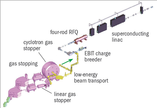
The approach taken towards reacceleration at NSCL involves slowing a high-energy beam by passing it through a solid degrader and bringing the ions to a stop, decreasing their initial spread of energy. The best-established stopping technology is the linear gas stopper – a tube of helium gas at pressures up to 1 bar. One important challenge, however, is to separate the desired isotopes from the many helium ions created during the stopping process. NSCL has already pioneered the use of these techniques to slow down isotopes produced by projectile fragmentation, allowing them to capture the isotopes in Penning traps for precision measurements.
In parallel, Georg Bollen and colleagues at NSCL are developing a cyclotron stopper, which should be quite effective for lighter isotopes. Instead of travelling along a tube of helium several metres long, the ions tangentially enter a gas tube where a magnetic field diverts them into a circular orbit. As they travel multiple times around the circumference, they lose energy and spiral toward the axis, where they can be collected. The compact geometry allows this to be done effectively in the tens of milliseconds needed to use short-lived isotopes. The NSCL team plans to explore both an advanced version of linear gas stopping and cyclotron gas stopping in the reacceleration project to evaluate how these steps contribute to the overall system.
Another enabling technology used for reacceleration is the breeding of high charges on the ions to get the maximum energy from limited acceleration voltage. The “classic” approach first accelerates singly charged ions, then passes them through foils to strip off electrons before further accelerating the multiply charged ions. This method – used, for example, in ISAC at TRIUMF – is robust and established, but creates a variety of charge states. Electron-cyclotron resonance plasmas, which are used in Japan and elsewhere for charge breeding, also create multiple charge states. Since only a single state can be selected, both of these techniques have an inherently limited efficiency in using precious rare isotopes.
NSCL will use a different breeder to increase the charges – namely the electron-beam ion trap, pioneered (as the EBIS) at REX-ISOLDE. Here, ions are electrostatically attracted to an intense electron beam as well as ionized by it. One advantage is that, by targeting stable electronic shells and selectively extracting charge states from the trap, the system can produce isotopes with a single high-charge state. “You can make use of noble-gas configuration – you get a nice enhancement in a single charge state,” explains Bollen.
Once the isotopes have high charges, they are reaccelerated using a standard superconducting linear accelerator. The initial plans at NSCL call for relatively modest energies (around 3 MeV per nucleon) but more cavities can be added as needed to boost the energy. The system is designed for efficient processing of rare isotopes at each stage, as well as for the efficient transfer between successive stages.
The technologies developed for this upgrade will provide important technical experience for the Facility for Rare Isotope Beams (FRIB), for which the US Department of Energy (DOE) has invited proposals. This machine would use a linear accelerator for the primary beam and provide higher initial isotope fluxes than the current cyclotron source at NSCL, which could make more experiments (including on the neutron-rich side) possible. Researchers at NSCL, who will explore how well the various components of the reacceleration project can scale to higher beam currents, have already laid the groundwork for FRIB. In autumn 2007, the laboratory published a detailed white paper describing a next-generation facility based on a superconducting 200 MeV, 400 kW heavy-ion driver with the possibility of experiments using fast, stopped and reaccelerated beams. These are all elements required for FRIB.
Karsten Riisager of CERN acknowledges that the NSCL upgrade will complement existing capabilities, noting that no single technical approach is superior. Although ISOL-based facilities like CERN’s REX-ISOLDE usually supply higher beam current, “for some of the exotic beams, such as short-lived isotopes, NSCL may have an advantage”, he says. Some elements are not available at all using ISOL techniques. He notes, however, that NSCL provides only nuclei lighter than about the mass of tin. “We [ISOLDE] are the only place right now where you have the very heavy nuclei reaccelerated.”
Bollen, who served as ISOLDE group leader in the late-1990s, and who plays a leading role at NSCL, is optimistic about the technology and science that the upgrade will enable. “We will produce reaccelerated beams which are not accessible at other facilities anywhere in the world now,” he says. Adds Gelbke: “History has taught us that new and unique tools often go hand in hand with new discoveries – and lead to further refinements based on the unique experience gained.”
During the last week of April, the ALICE experiment’s time-of-flight (TOF) detector was completed and installed in the experimental cavern. The TOF lies inside the huge magnet of ALICE, 3.7 m from the beamline. It will operate together with the time projection chamber, which lies inside the cylinder formed by the TOF, in identifying charged particles, such as pions, kaons and protons produced in collisions in ALICE.
The TOF detector has a total surface area of 150 m2. and is divided into 18 supermodules, each of which is further subdivided into five modules. It consists of 1638 strips of multigap resistive plate chambers, which were made at the INFN Laboratory in Bologna. Each module has been carefully checked for performance with cosmic rays before being assembled in the supermodules. Now that these modules are installed in the ALICE detector, all that remains for the team is to retest them to ensure that no damage occurred during installation and to connect and commission the electronics in the experimental cavern in preparation for start-up of the LHC.
To provide the best experiences, we use technologies like cookies to store and/or access device information. Consenting to these technologies will allow us to process data such as browsing behavior or unique IDs on this site. Not consenting or withdrawing consent, may adversely affect certain features and functions.
Functional
Always active
The technical storage or access is strictly necessary for the legitimate purpose of enabling the use of a specific service explicitly requested by the subscriber or user, or for the sole purpose of carrying out the transmission of a communication over an electronic communications network.
Preferences
The technical storage or access is necessary for the legitimate purpose of storing preferences that are not requested by the subscriber or user.
Statistics
The technical storage or access that is used exclusively for statistical purposes.The technical storage or access that is used exclusively for anonymous statistical purposes. Without a subpoena, voluntary compliance on the part of your Internet Service Provider, or additional records from a third party, information stored or retrieved for this purpose alone cannot usually be used to identify you.
Marketing
The technical storage or access is required to create user profiles to send advertising, or to track the user on a website or across several websites for similar marketing purposes.