Under a cloud of volcanic ash, the first annual meeting of the European Co-ordination for Accelerator Research & Development (EuCARD) project took place at the Rutherford Appleton Laboratory of the UK’s Science and Technology Facilities Council (STFC). From 13–16 April, this melting pot of ideas saw neutrino physicists mix with collimator designers, RF experts and magnet specialists to discuss progress with the EuCARD project as well as cutting-edge topics in accelerator sciences. EuCARD is a four-year project co-funded by the EU’s Framework Programme 7 (FP7), which involves 37 partners from 45 European accelerator laboratories, universities, research centres and industries.
The attendees, more than 100 in number, heard how the EuCARD networks (neutrino facilities, accelerator performance and RF technologies) had successfully oriented themselves towards efficient topical meetings, including the successful mini-workshop on LHC crab cavities that took place in October 2009. Two of these networks are currently considering increasing their scope to include plasma-wave acceleration and medical accelerators.
The collaborative R&D studies, whether on magnets, collimation, linear-collider technologies or advanced concepts, have demonstrated effective collaborations with promising progress. Out of many examples, the highlights presented at the meeting included an implementation strategy for crab-crossing at the LHC described by Rama Calaga of Brookhaven and progress in the design of a new compact crab cavity presented by Graeme Burt of Lancaster University. Many success stories provided food for thought, including impressive results on crab-waist luminosity at Frascati reported by Catia Milardi of INFN and prototyping of cryogenic collimators at the Facility for Antiproton and Ion Research, as Peter Spiller of GSI described. Whetting everyone’s appetite for a new type of acceleration was the talk by Allen Caldwell, of the Max Planck Institute for Physics, on proton-driven plasma-wave acceleration, following on from a recent EuCARD workshop. Future facilities for neutrinos were also part of the event with animated discussions about superbeams, beta beams and neutrino factories.
The EU strongly promotes access to European facilities, and within EuCARD opportunities are now open to external researchers. Four teams have already received EU support for access to the MICE facility at the Rutherford Appleton Laboratory, while the HiRadMat facility is at a design stage at CERN.
Enlarging the vision beyond EuCARD, guest speakers from related projects included Roland Garoby from CERN on the preparatory phase for an LHC upgrade (SLHC-PP); Eckhard Elsen from DESY on high-gradient superconducting RF cavities for an International Linear Collider (ILC-HiGrade); and Brigitte Cros of the French National Center for Scientific Research (CNRS) on the EuroLEAP project on laser-driven plasma-wave acceleration. Eric Prebys of Fermilab and the US LHC Accelerator Research Program showcased the strong R&D collaborations between the US and Europe, as well as exceptional advances in magnet design. Tord Ekelöf of Uppsala University and Roy Aleksan of the French Atomic Energy Commission (CEA) and the European Steering Group on Accelerator R&D (ESGARD) put EuCARD’s contribution towards the global accelerator R&D effort into perspective. A natural outcome was a discussion, under the auspices of ESGARD, of ways and means to tighten European and global collaborations.
Holding the meeting at the Rutherford Appleton Laboratory allowed attendees to visit the ISIS neutron source and the Diamond Light Source facility. In addition, staff from STFC presented aspects of the UK programme, notably Susan Smith with a summary of the ALICE and EMMA facilities at Daresbury and Mike Poole with an overview of STFC’s programme of accelerator R&D.
In his concluding remarks, CERN’s Jean-Pierre Koutchouk, the EuCARD project co-ordinator, acknowledged the quality and interest of the presentations, and the promising first results of this 4-year project. He thanked the 37 European partners for their dedication and dynamism and the STFC for the outstanding organization of the meeting at the Rutherford Appleton Laboratory.
The National Synchrotron Radiation Research Center (NSRRC), situated about one hour’s drive from Taipei, has begun the construction of its second synchrotron-light source, the Taiwan Photon Source (TPS), with a ground-breaking ceremony that took place on 7 February. Like any other large-scale project, reaching this milestone involved years of preparation and intense decision-making. The project requirements left little room for even small deviations from delivery timetables or for cost increases. To meet its mandate on time, the NSRRC has relied on its experienced staff members, many of whom had previously participated in the construction of the Taiwan Light Source (TLS) in 1983 – the first accelerator at NSRRC. This is allowing the project to meet challenging deadlines and to transfer expertise to younger engineers.
The TPS is a $210 million project involving, at various times, more than 150 staff in charge of design, construction, administration and management of day-to-day operations. The official proposal for the TPS was submitted in 2006 and primary funding was provided by the National Science Council over a seven-year period, with $54 million for civil construction backed by the Council for Economic Planning and Development. Conceptual designs of the major systems were completed in 2009 and key systems are currently under construction. These include the linac, the cryogenic system, the magnets and the RF transmitters.
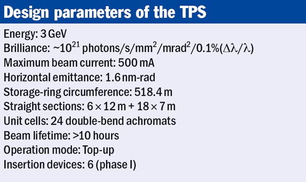
The TPS will be equipped with a 3 GeV electron accelerator and a low-emittance synchrotron-storage ring 518.4 m in circumference (see table). This will be housed in a doughnut-shaped building, 659.7 m in outer circumference, next to the smaller circular building that houses the existing 1.5 GeV accelerator, the TLS. The dual rings will serve scientists from South-East Asia and beyond who require an advanced research facility for conducting experiments with both soft and hard X-rays.
The storage ring
The TPS storage ring comprises 24 bending sections, 6 long straight sections and 18 short ones. A mock-up of a unit cell representing 1/24 of the storage ring has been constructed to test all systems before mass production, including the 14-m long vacuum pipe, prototype magnets and girders. This mock-up will be useful for evaluating and correcting – if necessary – specific design decisions. It has also served as a case study for the Machine Advisory Committee that reviewed the status of the TPS from technical and scheduling standpoints. One significant benefit gained from such a mock-up is that it allows for the spatial study of components that fit closely together, as well as of the cables and piping.
The vacuum chambers are made of aluminium alloy, based on the merits of lower impedance, lower heat resistance and its outgassing rate. There are two bending chambers per unit cell, each 4 m in length with, in some places, a 1 mm gap to the adjoining sextupole magnet in a bending section. In total there are 48 such units in the storage ring, with walls typically 4 mm thick in the straight sections. The beam pipes are made from aluminium extrusions with two cooling channels on each side. There are also several long vacuum chambers to cope with undulators installed between the magnet poles.
From vacuum to RF
A 14-m long vacuum pipe was produced as part of the 1/24 mock-up. Foreseeable production challenges include the development of machining and cleaning, of welding and cooling systems for the bending-chambers, and of a means to transport the finished product from the assembly site to the TPS storage ring. To minimize the mechanical distortion caused by thermal irradiation of the vacuum chambers, cooling-water channels are attached on both sides of the pipe and where the beam-position monitors (BPMs) are located. To transport the 14-m long vacuum pipe, a “hanger” of equivalent size was built to carry the assembled unit. A successful rehearsal, moving the transportation gear along 8 km of busy streets took place in March. The next step will be to ensure that no damage occurs to the vacuum pipe during the process.
To achieve optimal performance, the TPS accelerator will be mounted on metal girders placed on pedestals that can be adjusted via remote-control. The mock-up has demonstrated the sophistication reached in the design of these girders. Metal girders often suffer from rather low eigenfrequencies compared with concrete girders, especially when heavy magnets are placed on them. The TPS girders, however, are very stiff, which pushes up the eigenfrequencies. Measurements so far are in close agreement with predicted performance.
The TPS is designed for “top-up” operation, which is the standard operation mode in the TLS. The TPS injector complex will consist of a 150 MeV linear accelerator and a full-energy booster that will share the tunnel with the storage ring. Because this is a new facility with a low-emittance injector, the opportunity exists for using pulsed multipole injection, which may have significant benefits for quiet top-up. To allow acceptance tests of the linac before the storage-ring tunnel becomes available, construction work is under way on a bunker that will see future use for a Free-Electron-Laser (FEL) injector test facility.
Each of the 24 achromatic bending sections (unit cells) in the TPS contains 2 dipoles, 10 quadrupoles and 7 sextupoles. A further 168 skew quadrupoles, 1 injection septum-magnet and 4 kicker magnets, bring the total number of magnets to be installed to 629. All of the magnetic cores are made of silicon-steel sheet. The shaping of the iron laminations are made by wire cutting with computer numerical control machines to within 10 μm accuracy and are shuffled to ensure uniform magnetic properties. Accuracy in the magnet assembly is to be controlled to within 15 μm. The upper half of the magnet can be removed to install the vacuum chamber and the whole magnet can be detached without removing the vacuum chamber. The entire design for the magnet was performed in house with prototypes produced during phase I for thorough testing and measurement.
The TPS adopts the KEK approach to superconducting RF (SRF) to cope with future operational modes. Collaboration and technology transfer on the 500 MHz SRF module, as used at KEK for KEKB, is a de facto requirement to ensure the timely development of the SRF modules (including the 1.8 K cryostat for the harmonic SRF modules) and of technology-transfer for a higher-order-mode damped superconducting cavity suited to high-intensity storage rings. Conventional PETRA-type cavities will be considered as an alternative for commissioning in case the SRF cavities are not available in time.
The complexity and cost of constructing a new accelerator facility adjoined to an existing one is much higher than for one built on undeveloped land. However, to optimize resources and personnel, and the use of common equipment, as well as to allow a versatile research facility for users of both accelerators, the decision was taken to build the TPS at the NSRRC home base.
The site slopes down from south to north and abruptly descends 5 to 10 m at the northern edge, where the TPS will be built. The geology around the site is simple with gravel as the main formation. Ideally, the platform for the storage ring would be created above ground or by digging underground. The first approach is expensive and risks instability in an area known for frequent earthquakes; the latter will magnify the humidity problems in land soaked with rain and may cause a partial, if not total, subsidence of the existing TLS. To keep the civil construction cost within budget, the solution has been to meet both alternatives half way. The TPS storage-ring building will have its floor at the beamline area 12.5 m underground near the south side, and 4 m above ground at the north side. A beamline for medical imaging will be located on the west side next to the busiest traffic of the Hsinchu Science Park, while beamlines demanding nanoscale resolution will be located away from the possible sources of vibration.
Building a new accelerator next to an existing one involves continual challenges
Building a new accelerator next to an existing one involves continual challenges. Because the TPS building cuts into the edge of the TLS, the prevention of instability and vibration in the TLS caused by the construction work is a critical issue. To prepare for this daunting task, the NSRRC held workshops on ambient ground motion and civil engineering for the TPS in 2005 and 2008, so as to study the methods and strategic solutions used at other synchrotron facilities. These resulted in mechanical approaches to eliminate or reduce amplification of the floor motion by the girder system for the TPS, while also adding steel piles to prevent the adjacent TLS foundations from gradually crumbling.
Various methods to protect the TLS foundations and building centre on supporting the ground soil with in situ reinforcing and shoring-up the longitudinal sections that are exposed by excavation work. Taking advantage of the fact that the site is mainly of gravel formation, the TLS beam columns were reinforced with additional frames. In addition, seven H-beam, Type-L steel piles, 17.5 m long, were inserted in places where parts of walls of the TLS storage ring previously stood. Each pile was also equipped with a 200 cm × 120 cm × 60 cm concrete beam laid horizontally against the TLS foundations. These piles provide pressure to prevent the TLS from rising through elastic deformation occurring when the suppression disappears as a result of the 10 m-deep excavation.
To meet the target milestone of commissioning by the end of 2013, civil construction and accelerator installation will proceed concurrently. Partial occupancy of the linac building and ring tunnel needs to occur by the beginning of 2012 to meet the installation timetable for ring components. Power and other utilities will be brought in once pedestal paving and the installation of piping and cable trays begins. This will allow the setting up of the booster ring and subsystems in the storage ring. The SRF cavity will be the final component to move in and tests for TPS commissioning will follow accordingly.
With the accumulated expertise from the past, the design of the TPS has been achieved by the NSRRC’s own members. With their capability in developing insertion devices for the TLS and systems to cope with their operation established since 1993, the photon energy of the TPS should reach 30 keV. With a maximum brightness of 1021 photons/s/0.1%BW/mm2/mrad2 at 10 keV it will be among the brightest light-sources available.
The big LHC experiments have been 20 years in the making; the meeting at which the proto-collaborations first presented their ideas publicly took place in Evian-les-Bains in March 1992. Over the past few years, as the huge and complex apparatus neared completion, they have gathered data from cosmic rays. While this was important for testing and aligning the multilayered detectors, as well as for exercising data-acquisition systems, it was only in November and December last year that the collaborations had their first sight of the long-awaited collisions at the LHC, first at 900 GeV in the centre of mass and then at 2.36 TeV. Collision data at 7 TeV are now beginning to roll in (The LHC’s new frontier). In the meantime the collaborations have been eager to make the most of the data obtained last year and the first LHC physics publications have appeared.
The ALICE collaboration was first off the mark in 2009, with the submission of a paper on the analysis of the 284 events recorded during the first burst of collisions on 23 November. The paper, which presents the measurement of the pseudorapidity density of charged primary particles in the central region at 900 GeV in the centre of mass, was accepted for publication in European Physical Journal C on 3 December (ALICE Collaboration 2010). It compares the measurement on proton–proton collisions at the LHC with those from earlier experiments, including UA1 and UA5 at CERN, which collected data for proton–antiproton collisions at 900 GeV in the centre of mass.
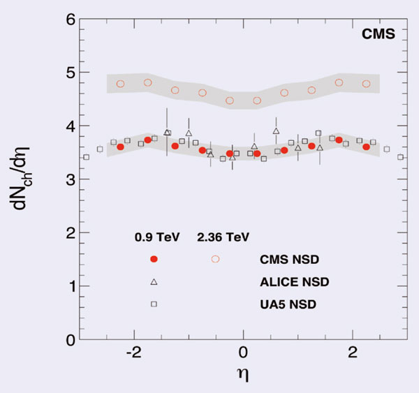
On 4 February the CMS collaboration followed suit with a submission to the Journal of High-Energy Physics, which was refereed and accepted for publication three days later. This paper presents measurements of inclusive charged-hadron transverse-momentum and pseudorapidity distributions for proton–proton collisions at both 900 GeV and 2.36 TeV, based on data collected in December (CMS collaboration 2010). The results at 900 GeV are in agreement with previous measurements (in UA5 and UA1) and in ALICE, and they confirm the expectation of near-equal hadron production in proton–antiproton and proton–proton collisions. The results at 2.36 TeV are in a new high-energy region, however, and they indicate an increase of charged-hadron multiplicity with energy that is steeper than expected.
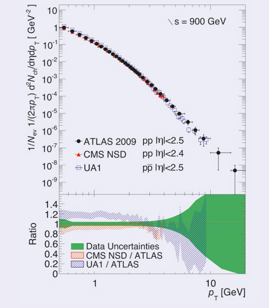
On 16 March, it was the turn of ATLAS, with a paper submitted to Physics Letters B entitled “Charged-particle multiplicities in pp interactions at √s = 900 GeV measured with the ATLAS detector at the LHC”. This details the collaboration’s first measurements with some 300,000 inelastic events collected in December using a minimum-bias trigger during collisions at 900 GeV (ATLAS collaboration 2010). It presents results for the charged-particle multiplicity, its dependence on transverse momentum and pseudorapidity, and the relationship between mean transverse momentum and charged-particle multiplicity, measured for events with at least one charged particle in the kinematic range η <2.5 and pT> 500 MeV. The results indicate that the charged-particle multiplicity per event and unit of pseudorapidity at η = 0 is some 5–15% higher than the Monte Carlo models predict.
These papers are just the first glimpses of physics at the LHC. To support what is set to be an extensive programme of physics, the LHC Physics Centre at CERN has recently started up. It aims to collect together a variety of initiatives to support the LHC physics programme, from the organization of workshops to the development of physics tools (see http://cern.ch/lpcc).
The world’s most in-demand isotope for medical-imaging purposes is 99mTc, a daughter of the isotope 99Mo. 99Mo has been produced in plentiful supplies for the entire world chiefly by two research reactors: one in Canada and the other in the Netherlands. Both of these reactors are currently down for difficult repairs related to their age – the younger one is 47 years old.
One mitigating factor in maintaining the supply of 99Mo has been the immense co-operation among medical-isotope suppliers and consumers around the world, primarily brokered through working groups of the International Atomic Energy Agency and several industrial associations. However, in the face of the supply shortages – the pair of reactors produced 65% of the world’s 99Mo – Canada has been examining alternatives.
At the end of March the government of Canada released its policy response to an expert advisory panel that analysed the situation in autumn 2009. The report highlights two main alternatives to manufacturing the 99Mo isotope that is currently in so much demand: cyclotrons (with new target materials) and linear accelerators (using photo-neutron processes on 100Mo or photo-fission of 238U).
Cyclotrons have been used around the world for four decades to produce isotopes useful for medical-imaging purposes ranging from 11C and 18F to 82Sr. The primary method to be explored for the cyclotron approach to the manufacture of 99mTc utilizes the 100Mo(p,2n)99mTc reaction. When bombarding the 100Mo target foil with an energetic proton beam, 99mTc is produced in direct reactions and can then be extracted. High yields of 99mTc from this reaction depend on three things: high-energy cyclotrons, high-intensity beams and high-efficiency 100Mo targets – all of which will be developed and tested in the next year or so.
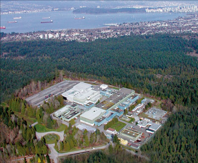
Along with a team of researchers and clinicians from across Canada, TRIUMF, the University of British Columbia and BC Cancer Agency have received initial Canadian government support to begin benchmarking and then optimizing the 99mTc yield from this process. Other groups are following suit along with several private companies.
If the technology pans out, and the contamination of ground-state 99Tc is controllable in the extracted 99Tc samples, it will be a new “killer app” for medical-isotope cyclotrons. Fine-tuning will be needed to select the optimal beam energy of the protons as well as the target geometries and the extraction and separation procedures. 99mTc produced directly at cyclotrons would be limited to local use because the six-hour half life prevents it from being shipped round the world as 99Mo currently is (with a 66-hour half life). However, this technology could provide an important supplement in major urban centres where cyclotron capacity exists for burgeoning nuclear-medicine departments. Cyclotron-produced 99mTc would reduce the need for 99Mo from reactors.
Independent of this innovation, cyclotrons have a bright future in nuclear medicine. The new isotopes and radiopharmaceuticals being developed using the so-called PET isotopes could eventually overtake the market dominance of 99Mo, so that cyclotrons will be everywhere.
On 2 December 2009 the CERN Research Board approved the LHC’s seventh experiment: the Monopole and Exotics Detector At the LHC (MoEDAL). The prime motivation of this experiment is to search for the direct production of the magnetic monopole at the LHC. Another physics aim is the search for exotic, highly ionizing, stable (or pseudo-stable) massive particles (SMPs) with conventional electric charge. Although MoEDAL is a small experiment by LHC standards it has a huge physics potential that complements the already wide vista of the existing LHC experiments.
The scientific quest for the magnetic monopole – a single magnetic charge, or pole – began during the siege of Lucera in 1269 with the Picard Magister, Petrus Peregrinus. He was a Franciscan monk, a soldier, a scien-tist and a former tutor to Roger Bacon, who considered him the fore-most experimentalist of his day. It was during this siege that Peregrinus put the finishing touches to a long letter entitled the Epistole de Mag-nete, which is his only surviving work. In this document, Peregrinus scientifically established that magnets have two poles, which he called the north and south poles.
In 1864 the Scottish physicist James Clerk Maxwell published the 19th-century equivalent of a grand unified theory, which encompassed the separate electric and magnetic forces into a single electromagnetic force (Maxwell 1864). Maxwell banished isolated magnetic charges from his four equations because no isolated magnetic pole had ever been observed. This brilliant simplification, however, led to asymmetric equations, which called for the aesthetically more attractive symmetric theory that would result if a magnetic charge did exist. Thirty years later, Pierre Curie looked into the possibility of free magnetic charges and found no grounds why they should not exist, although he added that it would be bold to deduce that such objects therefore existed (Curie 1894).
Paul Dirac, in a paper published 1931, proved that the existence of the magnetic monopole was consistent with quantum theory (Dirac 1931 and 1948). In this paper, he showed that the existence of the magnetic monopole not only symmetrized Maxwell’s equations, but also explained the quantization of electric charge. To Dirac the beauty of mathematical reasoning and physical argument were instruments for discovery that, if used fearlessly, would lead to unexpected but valid conclusions. Perhaps the single contribution that best illustrates Dirac’s courage is his work on the magnetic monopole. Today, magnetic-monopole solutions are found in many modern theories such as grand unified theories, string theory and M-theory. The big mystery is, where are they?
In the 1980s, two experiments found signals induced in single superconducting loops that could have indicated the passage of monopoles, but firmer evidence with coincidences in two loops was never found. Cosmic-ray experiments have also searched for monopoles but so far to no avail. For example, the Monopole, Astrophysics and Cosmic Ray Observatory (MACRO) detector in the Gran Sasso National Laboratory has set stringent upper limits. High-energy collisions at particle accelerators offer another obvious hunting ground for monopoles. Searches for their direct production have usually figured at any machine entering a new high-energy regime – and the LHC will be no exception.
New limits
At CERN, the search for magnetic monopoles – using dedicated detectors – began in 1961 with a counter experiment to sift through the secondary particles produced in proton–nucleus collisions at the PS (Fidecaro 1961). Over the following years, searches took place at the Interacting Storage Rings and at the SPS. At the Large Electron–Positron (LEP) collider, the hunt for monopoles in e+e– collisions was carried out in two experiments: MODAL (the Monopole Detector at LEP), deployed at intersection point I6 on the LEP ring (Kinoshita et al. 1992); and the OPAL monopole detector, positioned around the beam pipe at the OPAL intersection point (Pinfold et al. 1993). These established new limits on the direct production of monopoles.
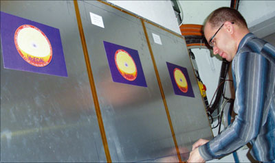
The international MoEDAL collaboration, made up of physicists from Canada, CERN, the Czech Republic, Germany, Italy, Romania and the US, is preparing to deploy the MoEDAL detector during the next long shutdown of the LHC, which will start late in 2011. The full detector comprises an array of approximately 400 nuclear track detectors (NTDs). Each NTD consists of a 10-layer stack of plastic (CR-39 and MAKROFOL) and altogether they have a total surface area of 250 m2. The detectors are deployed at the intersection region at Point-8 on the LHC ring around the VErtex LOcato (VELO) of the LHCb detector, as figure 1 indicates. The MoEDAL collaboration positioned 1 m2 of test detectors before the LHC was closed for operation in November 2009. Figure 2 shows the detectors being installed. If feasible, they will be removed for analysis during the planned short shutdown at the end of 2010 and a substantial subset of the full detector system will be deployed for the run in 2011.
The MoEDAL detector is like a giant camera for photographing new physics in the form of highly ionizing particles, and the plastic NTDs are its “photographic film”. When a relativistic magnetic monopole – which has approximately 4700 times more ionizing power than a conventional charged minimum-ionizing particle – crosses the NTD stack it damages polymeric bonds in the plastic in a small cylindrical region around its trajectory. The subsequent etching of the NTDs leads to the formation of etch-pit cones around these trails of microscopic damage. These conical pits are typically of micrometre dimensions and can be observed with an optical microscope. Their size, shape and alignment yield accurate information about the effective Z/β ratio, where Z is the charge and β the speed, as well as the directional motion of the highly ionizing particle.
The main LHC experiments are designed to detect conventionally charged particles produced with a velocity high enough for them to travel through the detector within the LHC’s trigger window of 25 ns – the time between bunch crossings. Any exotic, highly ionizing SMPs produced at the LHC might not travel through the detector within this trigger window and so will have a low efficiency for detection. Also, the sampling time and reconstruction software of each sub-detector is optimized assuming that particles are travelling at close to the velocity of light. Hence, the quality of the read-out signal, reconstructed track or cluster may be degraded for an SMP, especially for subsystems at some distance from the interaction point.
Another challenge is that very highly ionizing particles can be absorbed before they penetrate the detector fully. Additionally, the read-out electronics of conventional LHC detector systems are usually not designed to have a wide enough dynamic range to measure the very large dE/dx of highly ionizing particles properly. In the case of the magnetic monopole there is also the problem of understanding the response of conventional LHC detector systems to particles with magnetic charge.
The MoEDAL experiment bypasses these experimental challenges by using a passive plastic NTD technique that does not require a trigger. Also, track-etch detectors provide a tried-and-tested method to detect and measure accurately the track of a very highly ionizing particle and its effective Z/β. Importantly, heavy-ion beams provide a demonstrated calibration technique because they leave energy depositions very similar to those of the hypothetical particles sought. If it exists, a magnetic monopole will leave a characteristic set of 20 collinear etch-pits. There is no other conventional particle that could produce such a distinctive signature – thus, even one event would herald a discovery.
One of the world’s leading string theorists, Joseph Polchinski, has reversed Dirac’s connection between magnetic monopoles and charge quantization. He has posited that in any theoretical framework that requires charge to be quantized, there will exist magnetic monopoles. He also maintains that in any fully unified theory, for every gauge field there will exist electric and magnetic sources. Speaking at the Dirac Centennial Symposium at Tallahassee in 2002, he commented that “the existence of magnetic monopoles seems like one of the safest bets that one can make about physics not yet seen” (Polchinski 2003). The MoEDAL collaboration is working to prove him right.
On 30 March, just one month after CERN’s Large Hadron Collider (LHC) had restarted for 2010, control rooms around the 27 km ring echoed with cheers as the machine produced the first collisions at a record energy of 7 TeV in the centre of mass. Over the following days, the LHC experiments started to amass millions of events during long periods of running with stable beams, thus beginning an extended journey of exploration at a new energy frontier.
The first taste of beam for 2010, on 28 February, was at 450 GeV, the injection energy from the SPS (CERN Courier April 2010 p6). Operating the LHC at this energy soon became routine, allowing the teams to perform the tests necessary to optimize the beam orbit and the collimation, as well as the injection and extraction procedures. This work resulted in the definition of the parameters for collimation and machine protection devices for a “golden” reference orbit, with excellent reproducibility. It showed that the collimation system works as designed, with beam “cleaning” and other losses exactly where expected at the primary collimators. The tests also involved systematic and thorough testing of the beam dumping system, which proved to work well. One mystery about the beam still remains: the “hump”, a broad frequency-driven beam excitation that leads to an increase in the vertical beam size. Nevertheless, the teams measured good beam lifetimes, and in just under two weeks, on 12 March, the operators were able to ramp the beams up to 1.18 TeV, the highest energy achieved in 2009 (CERN Courier January/February p24).
A short technical stop followed, during which the magnet and magnet protection experts continued their campaign to commission the machine to 6 kA – the current needed in the main magnets to operate at 3.5 TeV per beam. A key feature is the quench protection system (QPS): on detecting the first indication that part of a superconducting magnet coil is turning normally conducting – quenching – it forces the whole coil to become normally conducting, thereby distributing the energy of the magnet current over its whole length. In the induced quench, the huge amount of energy stored in the coil is safely extracted and “dumped” into specially designed resistors. At the same time the QPS triggers a mechanism to dump beam within three turns.
In 2009, the system was fully commissioned to 2 kA, the current necessary to reach an energy of 1.18 TeV. However, during the final stages of hardware commissioning in February, multiple induced quenches sometimes occurred during powering off. It turns out that the system can be “over-protective”, because transient signals unrelated to real quenches can trigger controlled quenches. Once the problem was understood, the machine protection experts decided that they could solve it by changing thresholds in the magnet circuits equipped with the new QPS. For those parts with the old QPS, however, the solution required a modification to cards in the tunnel (to delay one of the transients). While awaiting full tests before implementing these changes (later in April), the experts took the decision to go ahead and run the main bending magnets up to 6 kA, but to limit the ramp rate to 2 A/s to reduce the transients.
By midday on 18 March the operators had the green light to try ramping to 6 kA at the agreed slow rate, first testing this ramp rate to 2 kA (1.18 TeV). By 10.00 p.m., after one or two interruptions, they had succeeded with a “dry ramp”, without beams. Work on beam injection and orbit corrections followed before a ramp started at around 4.00 a.m. with a low-intensity probe beam – about 5 × 10⁹ protons in a single bunch per beam. Gradually, the current in the main bending magnets rose from 460 to 5850 A and at about 5.23 a.m. the beams reached 3.5 TeV – a new world record at the first attempt. Already, measurements suggested a lifetime for both beams of as long as 100 hours.
Over the following days, machine studies at 3.5 TeV continued, with ramping becoming routine and the orbit stable and reproducible. Just as at 450 GeV, machine protection and collimation studies were important before the step to collisions at 3.5 TeV could take place. Only then would the operators be able to declare “stable beam” conditions so that the experiments could turn on the most sensitive parts of their detectors to observe events at the new high-energy frontier.
With some critical work still remaining, on 23 March the management took the decision to announce that the first attempt at collisions would take place a week later, on 30 March, with invited media in full attendance. The following days were not without difficulties, as a variety of hardware problems occurred, and each morning saw a change of plans in the run-up to the first collisions at 3.5 TeV per beam. Further planned running at 450 GeV and studies at higher intensities at 450 GeV were among the casualties. By 29 March, however, the operators had performed all of the essential tests for declaring “stable beams” at 3.5 TeV and were able to run the machine for several hours at a time, with a non-colliding bunch pattern to avoid premature collisions in any of the experiments.
Finally at 4.00 a.m. on 30 March the LHC team was ready to inject beam in a colliding bunch pattern with two bunches per beam, in preparation for collisions. After the necessary checks, they began the ramp to 3.5 TeV at 6.00 a.m. just as the first media were arriving on CERN’s Meyrin site. Twice, part of the machine tripped during the ramp and twice the operators had to ramp back down and re-establish beam at 450 GeV. The third attempt, however, from 11.52 a.m. to 12.38 p.m., was successful. Then, after some final measurements on the beam, it was time to remove the “separation bumps” – the fields in corrector magnets that are used to keep the beams separated at the interaction points during the ramp.
At 12.52 p.m. the operators announced that they were happy with the beam orbit and were about to remove the separation bumps. At 12.57 p.m. online beam and radiation monitors indicated that the CMS experiment had collisions, confirmed almost immediately by the online event displays. At 12.58 p.m. the ATLAS collaboration saw the experiment’s first events at a total energy of 7 TeV burst onto the screens of the crowded control room. At 12.59 p.m. the LHCb experiment saw its first collisions and by 1.01 p.m. the ALICE website was announcing its first 7 TeV events. At the same time, the two smaller LHC experiments also reported collisions. The TOTEM experiment saw tracks in one of its particle telescopes, while the LHCf calorimeters recorded particle showers with more than 1 TeV of energy. CERN’s press office swiftly told the assembled media and reported the successful observation of collisions at 7 TeV total energy to the world: the LHC research programme had finally begun.
At 1.22 p.m. the operators declared “stable beams” and the LHC provided three and a half hours of collisions before an error caused the beams to dump safely. During this time, CMS, for example, collected around 600,000 collision events and LHCf detected as many as 30,000 high-energy showers.
The following week saw several prolonged periods of “quiet” running during which the experiments continued to accumulate events. These were interspersed with further tests and machine development work. There were also scheduled periods for access to the tunnel, for example to begin work on the QPS to allow a faster ramp rate of 10 A/s. There was also the almost inevitable “down time” that arises with any complex machine.
The challenge ahead for the LHC team is to increase the luminosity, which is a measure of the collision rate in the experiments. The design luminosity is 1034 cm–2 s–1, but in these early days the experiments are seeing around 1027 cm–2 s–1. It is a case of learning to walk in small steps before running flat out, especially considering the total energy of the beams at higher luminosities. This is why the first investigations are always performed with the low-intensity “probe” beam.
The luminosity depends not only on how many particles are in the beams, but also on making sure that the beams collide head-on exactly at the interaction points. Ensuring that this happens is the goal of dedicated “luminosity scans” in horizontal and vertical beam position for the experiments at each of the four interaction points. In addition, the LHC operators can reduce the beam size at the collision points by “squeezing” the betatron function that describes the amplitude of the betatron oscillations about the nominal orbit. On 1 April the first squeeze from 11 m down to 2 m was successfully performed in several steps at Points 1 and 5, where ATLAS and CMS are located (together with LHCf and TOTEM, respectively).
By the end of the first week of April, each of the four large experiments had accumulated some 300 μb–1 of data, corresponding to several million inelastic events. When optimized and with about 1.1 × 10¹⁰ protons per bunch, they were recording data at a rate of up to around 120 Hz and finding a luminosity lifetime of well in excess of 20 hours. The first stage of the journey to attain 1 fb–1 before a long shutdown towards the end of 2011 had begun.
The Alpha Magnetic Spectrometer (AMS) left CERN on 12 February on the first leg of its journey to the International Space Station (ISS). The special convoy carrying the experiment arrived four days later at the European Space Agency’s research and technology centre (ESTEC) in the Noordwijk region of the Netherlands, after a journey of 600 km. AMS will then fly to the Kennedy Space Center in Florida before lifting off aboard the space shuttle, probably in July.
With an 8.5-tonne load filled with superfluid helium, this was no ordinary shipment. The AMS detector was inserted into a support structure and surrounded by protective plastic foil before being placed in a box and loaded onto the special vehicle, which also carried a diesel generator running a pump to keep the helium at 2 K. Some 20 members of the AMS collaboration followed the detector on its journey.
The detector components of AMS were constructed by an international team with significant contributions from France, Germany, Italy, Portugal, Spain and Switzerland, as well as from China, China (Taipei) and the US. Assembly then took place at CERN with help from the laboratory’s engineering services.
From 4–9 February, the detector was put through its paces using a test beam from the Super Proton Synchrotron (SPS). The AMS team used protons from the SPS to check the detector’s momentum resolution. It also tested the detector’s ability to distinguish electrons from protons. This is important for the measurement of cosmic rays, 90% of which are protons and constitute a natural background for other signals. The AMS collaboration will be looking for an abundance of positrons and electrons from space, one of the possible markers for dark matter.
The next step in testing has now moved to ESTEC, where ESA’s thermovacuum room simulates the vacuum in space. Here the team will test the detector’s capacity to exchange heat and thus maintain its thermal balance. This is essential to the functioning of the detector’s electronics and superconducting magnet, the first of its kind to be launched into space. If all goes well, towards the end of May the detector will embark on a journey to NASA’s Kennedy Space Center aboard a C5 aircraft owned by the US Air Force. There, it will board the last-but-one flight of the space shuttle Discovery (mission STS-134). Lift-off is scheduled for July.
Once docked to the ISS, AMS will examine fundamental issues about matter and the origin and structure of the universe directly from space. Its central aim is to search for dark matter and antimatter. Its data will be transmitted from the ISS to Houston and on to the detector control centre at CERN, as well as to a number of regional physics-analysis centres that have been set up by the collaborating institutes.
In the early hours of 28 February, beam was circulating again in the LHC at the start of operations that are scheduled to continue for the next 18 to 24 months. The objective is to deliver 1 fb–1 of data to the experiments at 7 TeV in the centre of mass, so providing enough data to make significant advances across a range of physics channels.
This restart followed a break of several weeks during which LHC teams carried out essential work to ensure the correct functioning of the magnets at high current. They verified several thousand channels of the new quench-protection system (nQPS) and measured precisely the resistance of the 10,000 splices connecting the magnets, finding no unacceptably anomalous values.
Once work on the nQPS had been completed, it was the turn of the hardware-commissioning team to test the main dipoles and quadrupoles of the LHC up to a current of 6 kA. This will allow proton collisions at 7 TeV in the centre of mass during the coming run. After completing these tests the hardware-commissioning team handed over to the operations team.
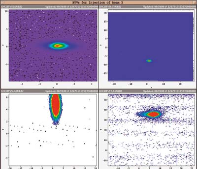
Their initial operations centred on tests without beam to verify the correct functioning of all of the machine systems in unison. Late on 27 February the LHC was ready to receive beam again, and by just after 4.00 a.m., protons had circulated in each direction round the machine. For the operations team this was the beginning of a period of optimization at the injection energy of 450 GeV, investigating parameters associated with beam injection, collimation and the beam-abort systems etc., as well as studies to improve the beam lifetime. The first ramps – without beam – were made on the evening of 9 March to an energy of 1.18 TeV, the highest level that was achieved in 2009. Ramps to 3.5 TeV per beam are scheduled for later in March, with collisions planned for the end of the month.
The first operational tests of the booster accelerator for the ALBA synchrotron light source in Barcelona took place in January. The results show that all of the components, subsystems and equipment perform according to specification. This was the main objective of the tests, which were performed over a short period so as not to interfere excessively with the installation of the storage ring and the beamlines.
ALBA is a third-generation synchrotron light-source facility co-financed by the Catalan and Spanish governments, which is now in its last phase of construction at Cerdanyola del Vallès, Barcelona. The facility, which is being constructed and operated by the CELLS consortium, will provide synchrotron light of world-class quality (brilliance) for research in a range of scientific disciplines.
The facility consists of three accelerators – the linac, booster and storage ring – and seven beamlines (in the initial phase). The linac creates the electron beam and accelerates it up to 100 MeV. The beam is then injected into the second accelerator, the booster, where the energy increases to 3 GeV. This is the critical part of the accelerator chain. Ultimately, the beam will be injected into the storage ring and stored to produce synchrotron light.
The operational test of the booster began on 21 December 2009, when beam was transported from the linac to the booster for the first time. After a Christmas shut-down, tests recommenced on 11 January and on the following day, beam made the first turns round the machine – and produced the first synchrotron light seen in Spain. On 19 January the ALBA team was able to accelerate the beam to 600 MeV and two days later they achieved 2.7 GeV with a circulating beam of 0.7 mA. The two-week test finished on 24 January to allow for further installation work.
ALBA’s booster was completely designed, assembled and tested by the ALBA team, making it the first high-energy accelerator built in Spain. With its design, it also has the smallest emittance (beam size) in the world for an accelerator of its kind. The next milestones will be the operation of the storage ring, in the autumn, followed by the operation of the complete facility, expected for the beginning of 2011.
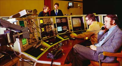
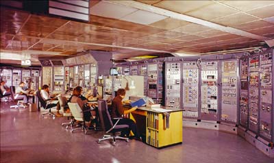
“The proton synchrotron currently being built by CERN (the SPS) will be controlled centrally from three control desks, each with its own minicomputer. Only a few knobs and switches must control all of the many thousands of digital and analogue parameters of the accelerator, and an operator will watch the machine on at most half-a-dozen displays … An advantage of the new form of control is that since there are so few controls and displays, they may be made more elaborate and powerful.”
Thus begins a CERN report written in May 1973 by Frank Beck and Bent Stumpe of the controls group (Beck and Stumpe 1973). It describes two devices: the touch screen and the computer-controlled knob. CERN’s member states had approved the construction of the Super Proton Synchrotron (SPS) in February 1971. With its circumference of nearly 7 km, it was a giant machine for its day – some 10 times the size of the Proton Synchrotron (PS) that had started up in 1959. The scale of the new machine meant that control via individual cables linking directly to a central control room – as was done for the PS – would be economically unfeasible. One of the first tasks of the nascent SPS controls group, therefore, was to find a practical and economical solution.
The timing was just right for developing central control supported by computers. Industry was beginning to commercialize minicomputers, so the idea began to take shape of equipping sectors locally with minicomputers controlled by message transfer from the central control room. This would overcome the enormous requirement for cables. The next question was how to create an “intelligent” system based on minicomputers to replace the thousands of buttons, switches and oscilloscopes that a conventional control system would need for a machine as large as the SPS.
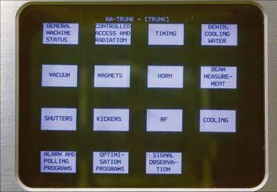
A human has only two hands, but if control devices could be redefined fast enough by computer, then only one button (or knob or pointing device) would be needed to do the job of controlling many different devices or parameters. The main uses of the “master button” would be to select accelerator subsystems for control and monitoring, as well as to select from hundreds of analogue signals the ones to show on displays at any one time. The minicomputers made by Norsk Data at the time seemed to be powerful enough for such a system.
Frank Beck, who was to become head of the SPS Central Controls, was aware of the possibilities offered by existing touch screen technology in which a panel of buttons with labels written by computer can be changed simply by touch to control different aspects of a system. By presenting successive choices that depend on previous decisions, the touch screen would make it possible for a single operator to access a large look-up table of controls using only a few buttons.
It was clear that the only practical way to create buttons with variable labels by computer at that time was on a cathode-ray tube (CRT) screen. The question then was how the computer could detect which button was being selected. The rather complicated mechanical designs that existed did not seem suitable for the SPS control system. For example, David Fryberger and Ralph Johnson at SLAC had invented a device based on acoustic waves – Rayleigh waves – travelling in the surface of a sheet of glass, which had already been used for accelerator control (Fryberger and Johnson 1971). This worked but required a bulky frame around the screen. Beck discussed this with his colleague Stumpe, from the Data Handling Division, and asked if he could suggest a better technical solution.
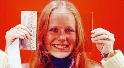
In a handwritten note dated 11 March 1972, Stumpe presented his proposed solution – a capacitative touch screen with a fixed number of programmable buttons presented on a display. It was extremely simple mechanically. The screen was to consist of a set of capacitors etched into a film of copper on a sheet of glass, each capacitor being constructed so that a nearby flat conductor, such as the surface of a finger, would increase the capacity by a significant amount. The capacitors were to consist of fine lines etched in copper on a sheet of glass – fine enough (80 μm) and sufficiently far apart (80 μm) to be invisible (CERN Courier April 1974 p117). In the final device, a simple lacquer coating prevented the fingers from actually touching the capacitors.
Stumpe was immediately recruited into the controls group to develop the necessary hardware and the first capacitor to prove that the idea worked was produced at CERN in 1973. Chick Nichols was able to use ion-sputtering equipment available in one of the workshops to evaporate a fine layer of copper or gold on a flexible, transparent Mylar sheet to make the first working device. A prototype glass screen with nine touch buttons followed soon after.
The fineness of the lines and their pitch meant that a great deal of care was needed to produce the screen, but it turned out to be possible with the techniques normally used to make printed circuit boards. At first, placing the copper layer on the glass appeared difficult and it proved impossible to get reliable adherence with vacuum deposition. However, ion sputtering gave better results. By ensuring that the glass was scrupulously clean and by depositing the copper slowly – an hour for a layer of about 10 μm – it was possible to get adherence strong enough to allow soldered connections to the glass.
The capacitance of each button was about 200 pF, increasing by about 10% when a finger came close. The method chosen to detect the change in capacitance was to use a phase-locked oscillator circuit, which had recently become available as a single integrated-circuit chip. One circuit acted as a reference oscillator, while each button had a similar circuit. The oscillator attached to a button locked in to the frequency of the reference oscillator (120 kHz), so that a change in capacity altered the phase but not the frequency. The phase shift was converted to a voltage shift, which indicated that the button had been touched. The circuit was very immune to noise and transients. Moreover, any drifts would be common to both oscillators, so good thermal stability could be obtained with commercial components.
As soon as it was clear that the system could successfully recognize which of the nine buttons was touched, Beck showed the prototype to those in charge of the SPS project. Even before reliability tests had been performed, the decision was taken to use the touch-screen system and begin development of the control software on the first minicomputers (Nord 1, and later Nord 10) that CERN had received from Norsk Data. This was definitely a risk, but had the decision not been made then the control group would have had no option but to use conventional technology for central control of the SPS. Tests later proved the reliability of the technique.
The next step was the development of a more practical touch screen with 16 buttons. The new central SPS control room needed several devices and industry was soon involved. Manufacturing of the touch screen itself proceeded in collaboration with a Danish company, Ferroperm. This led to the development of a robust glass screen with reduced surface reflections. At the same time another Danish company, NESELCO, became involved in producing the electronic modules needed to drive the touch screen.
When the SPS started up in 1976 its control room was fully equipped with touch screens – apparently the first application of the capacitative touch screen in the world. Touch screens later took their place in modernized control systems for the PS, which had preceded the SPS by nearly 20 years, as well as for the subsequent and much bigger Large Electron Positron collider. Some of these screens continued to operate until the new CERN Control Centre took over operations in 2006 – a lifetime of 30 years.
In 1977 CERN demonstrated the potential of the new touch screen for industrial control in no lesser a place than the huge and famous Hanover Fair. In the hall for new industrial inventions, CERN presented the “Drinkomat”, with a complete operational console similar to the one used to control the SPS, including a Nord 10 computer. The system was built by Alain Guiard, who at the time was using a touch screen to control a large film-development installation at CERN, which allowed exact control of the liquids used in the process. Through multiple choices on a touch screen, the Drinkomat allowed people to mix drinks and follow the process visually, foreshadowing the machines that came into CERN’s cafeterias nearly 30 years later.
By 1977 the capacitative touch screen was already available commercially and being sold to other users within CERN and to other research institutes and companies wishing to use the screens in their own control systems (Crowley-Milling 1977). Its use spread around the world: JET and the Rutherford Laboratory in the UK; KEK, Mitsubishi and the TOYO corporation in Japan; the Rigshospitalet in Denmark and the Hahn-Meitner Institute in Germany.
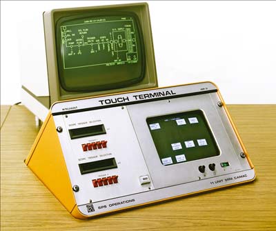
One reason behind the success of the system was a decision at CERN to build electronic modules in the CAMAC system, used not only all over CERN but throughout the world. This made it easy for users to buy individual modules for integration into their own systems. By 1980, more than 10 different CAMAC modules developed at CERN had been brought to the market by NESELCO. Furthermore, a CAMAC module with an integrated computer for driving the touch screen was developed in 1977, shortly followed by a CAMAC crate computer using the Motorola 68000 microprocessor. These modules were integrated into an intelligent “Touch Terminal”, which was commercialized by NESELCO in 1980; it was the world’s first commercial touch-screen computer.
At CERN the Touch Terminal was used for the control of the Antiproton Accumulator, which allowed the SPS to become a proton–antiproton collider and gather fame for CERN through the discovery of the W and Z bosons and the subsequent awarding of the Nobel prize to Carlo Rubbia and Simon van der Meer.
The original touch screen had only 16 fixed “buttons” associated with distinct areas of the screen, but already in 1978 it was obvious that a more flexible arrangement for dividing up the screen would have many advantages. Stumpe developed his original concept to create an X–Y touch screen, in which the idea was to sense the position touched via two layers of capacitors corresponding to X and Y co-ordinates. Following prototype work at CERN, development began with NESELCO and the University of Aarhus, supported by the Danish state development funds. The X–Y screen involved new techniques for metallization on various substrates, which became the subject of patent rights. Stumpe was asked to sign a nondisclosure agreement, which he refused to do because CERN required that all inventions should be published. At this point, CERN’s involvement with the further development of touch screens came to an end.
The new CERN Control Centre (CCC), which oversees the control of CERN’s entire accelerator complex, including the PS, SPS and now the LHC, has no touch screens for accelerator control. Today the use of the ubiquitous mouse as a pointing device provides the same type of computer control. Moreover, PC-based systems with standard displays are inexpensive and easy to install. In 1972, when the touch screen was developed at CERN for controlling the new SPS, the situation was different: nothing was commercially available and every control device had to be invented, including the colour displays.
However, touch screens are undoubtedly not absent from the CCC, as the operators often communicate with colleagues by mobile phones with capacitative touch screens. The idea invented at CERN in 1972 has been reinvented in many applications, from “Drinkomats” to rail and airline ticket machines to the multifunction phones that sit in many pockets – not only in the CCC but all around the world.
To provide the best experiences, we use technologies like cookies to store and/or access device information. Consenting to these technologies will allow us to process data such as browsing behavior or unique IDs on this site. Not consenting or withdrawing consent, may adversely affect certain features and functions.
Functional
Always active
The technical storage or access is strictly necessary for the legitimate purpose of enabling the use of a specific service explicitly requested by the subscriber or user, or for the sole purpose of carrying out the transmission of a communication over an electronic communications network.
Preferences
The technical storage or access is necessary for the legitimate purpose of storing preferences that are not requested by the subscriber or user.
Statistics
The technical storage or access that is used exclusively for statistical purposes.The technical storage or access that is used exclusively for anonymous statistical purposes. Without a subpoena, voluntary compliance on the part of your Internet Service Provider, or additional records from a third party, information stored or retrieved for this purpose alone cannot usually be used to identify you.
Marketing
The technical storage or access is required to create user profiles to send advertising, or to track the user on a website or across several websites for similar marketing purposes.