On 14 November, a beam of negative hydrogen ions was successfully accelerated for the first time to 3 MeV in Linac4. This marked the start of a two-year commissioning phase for the new linear accelerator that will replace Linac2 as the low-energy injector in CERN’s accelerator complex. When this chain of accelerators that ultimately serves the LHC is in operation, the negative hydrogen ions will be stripped of their two electrons and converted into protons at injection into the Proton Synchrotron Booster.
In the first months of 2013, the Linac4 collaboration commissioned the radio-frequency quadrupole (RFQ) at a dedicated test stand. The 1.5-tonne RFQ, constructed completely at CERN, sits at the start of the Linac4 beam line and takes the beam from 45 keV to 3 MeV in just 3 m.
During the summer, the team moved the RFQ, the medium-energy beam transport (MEBT) line and the diagnostic line to their final location in the Linac4 tunnel. In parallel, a new negative-hydrogen-ion source was assembled, installed and successfully commissioned in the tunnel. After a short RF commissioning period, the beam was accelerated to 3 MeV and transported to the beam dump at the end of the diagnostic line.
By the end of 2013 – only a few months into installation – most of the Linac4 infrastructure was in place. Not only have the RFQ and MEBT, with its fast beam chopper, been placed in their final locations, the majority of the RF klystrons on the surface have also been installed. In parallel, a second-generation negative-hydrogen-ion source has been commissioned on the test stand, delivering a beam in excess of 50 mA just before the end of the year.
Once commissioning to 3 MeV is completed in February, three more RF accelerating sections will be installed progressively to take the ion beam to its final energy. Drift tube linacs (DTL) will take the beam to 50 MeV; cell-coupled DTLs will take it to 100 MeV; and, finally, pi-mode accelerating structures will take it up to 160 MeV.
The TOTEM collaboration has made the first measurement of the double diffractive cross-section in the very forward region at the LHC, in a range in pseudorapidity where it has never been measured before.
Double diffraction (DD) is the process in which two colliding hadrons dissociate into clusters of particles, the interaction being mediated by an object with the quantum numbers of the vacuum. Because the exchange is colourless, DD events are typically associated experimentally with a large “rapidity gap” – a range in rapidity that is devoid of particles.
The TOTEM experiment – designed in particular to study diffraction, total cross-sections and elastic scattering at the LHC – has three subdetectors placed symmetrically on both sides of the interaction point. Detectors in Roman pots identify leading protons, while two telescopes detect charged particles in the forward region. These two telescopes, T1 and T2, are the key to the measurement of double diffraction in the very forward region. T2 consists of gas-electron multipliers that detect charged particles with transverse momentum pT > 40 MeV/c at pseudorapidities of 5.3 < |η| < 6.5. The T1 telescope consists of cathode-strip chambers that measure charged particles with pT > 100 MeV/c at 3.1 < |η| < 4.7. (Pseudorapidity, η, is defined as –ln(tan θ/2), where θ is the angle of the outgoing particle relative to the beam axis, so a higher value corresponds to a more forward direction.)
For this novel measurement, TOTEM selected the DD events by vetoing T1 tracks and requiring tracks in T2. This is equivalent to selecting events that have two diffractive systems with 4.7 < |η|min < 6.5, where ηmin is the minimum pseudorapidity of all of the primary particles produced in the diffractive system. The measurement used data that were collected in October 2011 at a centre-of-mass energy of 7 TeV during a low pile-up run with special β* = 90 m optics and with the T2 minimum-bias trigger. After offline reconstruction, the DD events were selected by requiring tracks in both T2 arms and no tracks in either of the T1 arms. This allowed the extraction of a clean sample of double-diffractive events.
The analysis of these events led to a result for the double diffraction cross-section of σDD = (116±25) μb, for events where both diffractive systems have 4.7 < |η|min < 6.5. The measured values for the cross-section are between the predictions of the hadron-interaction models, Pythia and Phojet, for the corresponding ranges in η.
Mention CESAR today in accelerator circles and the likely reaction will be “Caesar who?” However, the CESAR we are writing about was not a person. It was the CERN Electron Storage and Accumulation Ring – a small machine, just 24 m in circumference, but of decisive importance for the direction in which CERN’s accelerators evolved. To understand why, we have to go far back in CERN’s history, to well before the first beam in the 26 GeV Proton Synchrotron (PS).
In 1956, when components for the PS were starting to be assembled, thoughts were already turning to what should come after. So in 1957, a group was constituted within the PS Division for research on new ideas for high-energy accelerators. An intensive exchange on such ideas ensued between CERN, the US and Novosibirsk (in what was then the USSR). Theoretical studies were supplemented by building prototypes for experimental studies and plans were made for entire model accelerators.
Apart from accelerators with energies well beyond that of the future PS, the concept of colliding beams – where the centre-of-mass energy would be orders of magnitude higher than achievable with beams on stationary targets – was gaining interest. The problem, however, was in obtaining sufficient beam intensity. The novel idea of “beam stacking”, i.e. accumulation of many beam pulses of low intensity into a beam of high intensity, pioneered by a group at the Midwestern University Research Association (MURA) in the US, showed the way to go.
The PS started up brilliantly in November 1959, soon far exceeding its design intensity of 1010 protons per pulse and promising to go much further. That opened the possibility for the PS to be the injector for a proton–proton collider consisting of two synchrotron rings, in which successive PS pulses would be accumulated through beam stacking at 26 GeV, without the need for further acceleration. However, experience with beam stacking needed to be gained and important aspects of the collider rings had to be verified experimentally. To this end, the design of a small strong-focusing synchrotron-type model started in 1960 – and so CESAR was conceived.
As a model, CESAR had to be small – 24 m in circumference – and yet the particles had to be highly relativistic, which meant the use of electrons. On the other hand, effects from synchrotron radiation had to be negligible, which meant low magnetic fields – 130 G (13 mT) in the bending magnets – and a corresponding kinetic energy of 1.75 MeV. The 2 MV van de Graaff generator already ordered for the fixed-field alternating-gradient (FFAG) model that CERN had previously intended to build therefore fitted the bill as injector.
In 1961, the group that had been formed in 1957 was extended to become the Accelerator Research Division. It had groups to design the Intersecting Storage Rings (ISR) and the 300 GeV machine, which was to become the Super Proton Synchrotron. The CESAR group completed both the design of the storage-ring model and the ordering and building of components that had begun in 1960, and prepared for construction in a new experimental hall. Construction, installation of the magnet system and, in particular, the preparation of the vacuum system took place in 1962–1963. During this time, the long-awaited van de Graaff generator arrived. Its conditioning took months, through which loud bangs from spark-overs rang around the hall.
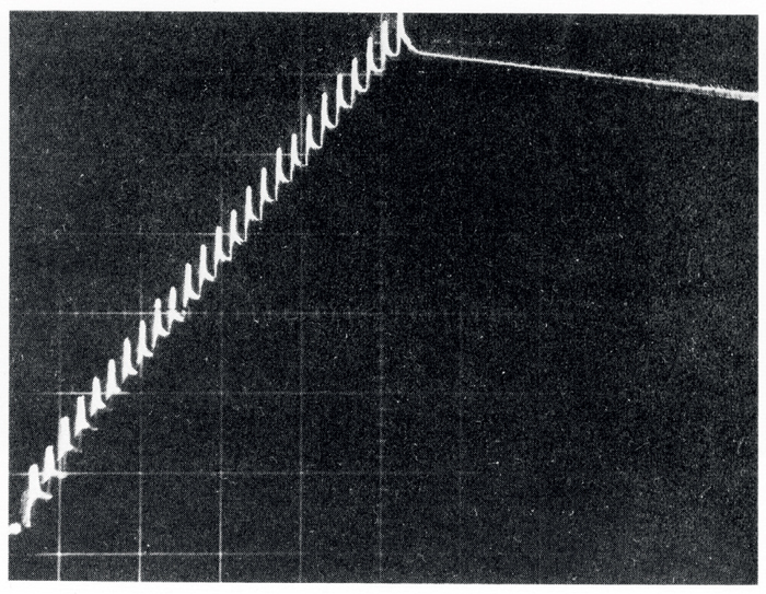
Finally, in summer 1963, the first beam was injected into the completed CESAR (figure 1). However, it would not circulate. To make it do so turned out to be a tedious job. The cause was that the magnetic fields were extremely low – 130 G in the bending magnets and a mere 15 G (1.5 mT) at the poles of the quadrupole magnets – compounded by the fact that the magnets were not laminated but made of massive soft iron. After powering a bending magnet, it took more than a day for its magnetic field to settle down to within 10–4 of its final value. The overhead crane had always to be parked at the end of the hall, as its position influenced the path of the electrons. Jokingly, we even evoked the phase of the Moon! Every power failure was a catastrophe, from which it took days to recover. Nevertheless, we finally made it. Early in the morning of 18 December 1963, the beam circulated.
A challenging experimental and technical programme lay ahead. Foremost, we had to demonstrate RF-capture of the injected beam and beam stacking and measure the stacking efficiencies for various modes of stacking. Of equal importance, we had to prove that a vacuum of 10–9 Torr, as required for the ISR, could be achieved in an extended accelerator system. We also had to measure beam lifetime in terms of number of turns, as an input to the considerations about long-term stability of the ISR beams. Later, there were also studies of the influence of higher-order resonances on emittance and beam lifetime.
Through 1964 and 1965, beam stacking was the dominant topic. Measurements showed that the stacking efficiency depended on various parameters more or less as theory and simulations predicted. Several variants of the stacking process were successfully developed, all with high efficiency and some approaching 100%. The vacuum system reached pressures of 2 × 10⁻⁹ Torr and clearly showed that lower pressures could be achieved. The beam lifetime of about 1 s was consistent with the calculated scattering on the residual gas.
In June 1965, CERN Council approved the ISR Project. CESAR had done its job
By early 1965, we therefore had enough positive results to bolster the conviction that the ISR could achieve sufficiently intense beams with sufficiently long lifetimes. In June 1965, CERN Council approved the ISR Project. CESAR had done its job.
Experiments with CESAR, however, continued until the end of 1967, delivering a host of results that were useful later for the ISR, its vacuum system and its stacking operation. And there was another benefit from CESAR. It was an excellent accelerator school, from which several accelerator physicists emerged to play important roles in CERN’s subsequent projects.
One can muse about the course that CERN’s accelerator history might have taken without CESAR and its results. The ISR would not have been built. Would we then have dared to convert the SPS to a proton–antiproton collider? And without the competence and experience gained with these two colliders, would we have dared to propose the LHC? We opine that CESAR was decisive in setting CERN on the collider course – a course of great success – and that tiny CESAR is actually the great-grandfather of the giant LHC.
When a beam of protons passed through Fermilab’s Main Injector at the end of July, it marked the first operation of the accelerator complex since April 2012. The intervening long shutdown had seen significant changes to all of the accelerators to increase the proton-beam intensity that they can deliver and so maximize the scientific reach of Fermilab’s experiments. In August, acceleration of protons to 120 GeV succeeded at the first attempt – a real accomplishment after all of the upgrades that were made – and in September the Main Injector was already delivering 250 kW of proton-beam power. The goal is to reach 700 kW in the next couple of years.
With the end of the Tevatron collider programme in 2011, Fermilab increased its focus on studying neutrinos and rare subatomic processes while continuing its active role in the CMS experiment at CERN. Accelerator-based neutrino experiments, in particular, require intense proton beams. In the spring of 2012, Fermilab’s accelerator complex produced the most intense high-energy beam of neutrinos in the world, delivering a peak power of 350 kW by routinely sending 3.8 × 10¹³ protons/pulse at 120 GeV every 2.067 s to the MINOS and MINERvA neutrino experiments. It also delivered 15 kW of beam power at 8 GeV, sending 4.4 × 10¹² protons/pulse every 0.4 s to the MiniBooNE neutrino experiment.
Higher intensities
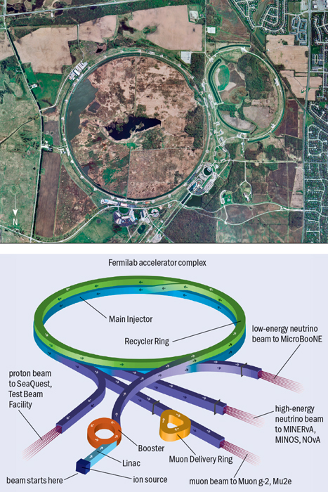
This level of beam intensity was pushing the capabilities of the Linac, the Booster and the Main Injector. During the shutdown, Fermilab reconfigured its accelerator complex (see figure 1) and upgraded its machines to prepare them for the new NOvA, MicroBooNE and LBNE experiments, which will demand more muon neutrinos. In addition, the planned Muon g-2 and Mu2e experiments will require proton beams for muon production. With the higher beam intensities it is important to reduce beam losses, so the recent accelerator upgrades have also greatly improved beam quality and mitigated beam losses.
Before the shutdown, four machines were involved in delivering protons for neutrino production: the Cockcroft–Walton pre-accelerator, the linear accelerator, the Booster accelerator and the Main Injector. During the past 15 years, the proton requests for the Linac and Booster have gone up by more than an order of magnitude – first in support of MiniBooNE, which received beam from the Booster, and then in support of MINOS, which received beam from the Main Injector. Past upgrades to the accelerator complex ensured that those requests were met. However, during the next 10 years another factor of three is required to meet the goals of the new neutrino experiments. The latest upgrades are a major step towards meeting these goals.
For the first 40 years of the laboratory’s existence, the initial stage of the Fermilab accelerator chain was a caesium-ion source and a Cockcroft–Walton accelerator, which produced a 750 keV H– beam. In August 2012, these were replaced with a new ion source, a radiofrequency quadrupole (RFQ) and an Einzel lens. The RFQ accomplishes transverse focusing, bunching and acceleration in a single compact device, significantly smaller than the room-sized Cockcroft–Walton accelerator. Now the 750 keV beam is already bunched, which improves capture in the following Linac (a drift-tube linear accelerator). The Einzel lens is used as a beam chopper: the transmission of the ions can be turned on and off by varying the voltage on the lens. Since the ion source and RFQ are a continuous-wave system, beam chopping is important to develop notches in the beam to allow for the rise times of the Booster extraction kicker. Chopping at the lowest possible energy minimizes the power loss in other areas of the complex.
The Booster, which receives 400 MeV H– ions from the Linac, uses charge-exchange injection to strip the electrons from the ions and maximize beam current. It then accelerates the protons to 8 GeV. For the first 30 years of Booster operation, the demand for proton pulses was often less than 1 Hz and never higher than about 2 Hz. With the advent of MiniBooNE in 2002 and MINOS in 2005, demand for protons rose dramatically. As figure 2 shows, in 2003 – the first year of full MiniBooNE operation – 1.6 × 10²⁰ protons travelled through the Booster. This number was greater than the total for the previous 10 years.
Booster upgrades
A series of upgrades during the past 10 years enabled this factor of 10 increase in proton throughput. The upgrades improved both the physical infrastructure (e.g. cooling water and transformer power) and accelerator physics (aperture and orbit control).
While the Booster magnet systems resonate at 15 Hz – the maximum number of cycles the machine can deliver – many of the other systems have not had sufficient power or cooling to operate at this frequency. Previous upgrades have pushed the Booster’s performance to about 7.5 Hz but the goal of the current upgrades is to bring the 40-year-old Linac and Booster up to full 15 Hz operation.
Understanding the aperture, orbit, beam tune and beam losses is increasingly important as the beam frequency rises. Beam losses directly result in component activation, which makes maintenance and repair more difficult because of radiation exposure to workers. Upgrades to instrumentation (beam-position monitors and dampers), orbit control (new ramped multipole correctors) and loss control (collimation systems) have led to a decrease in total power loss of a factor of two, even with the factor of 10 increase in total beam throughput.
Two ongoing upgrades to the RF systems continued during the recent shutdown. One concerns the replacement of the 20 RF power systems, exchanging the vacuum-tube-based modulators and power amplifiers from the 1970s with a solid-state system. This upgrade was geared towards improving reliability and reducing maintenance. The solid-state designs have been in use in the Main Injector for 15 years and have proved to be reliable. The tube-based power amplifiers were mounted on the RF cavities in the Booster tunnel, a location that exposed maintenance technicians to radiation. The new systems reduce the number of components in the tunnel, therefore reducing radiation exposure and downtime because they can be serviced without entering the accelerator tunnel. The second upgrade is a refurbishment of the cavities, with a focus on the cooling and the ferrite tuners. As operations continue, the refurbishment is done serially so that the Booster always has a minimum number of operational RF cavities. Working on these 40-plus-year-old cavities that have been activated by radiation is a labour-intensive process.
The Main Injector and Recycler
The upgrades to the Main Injector and the reconfiguration of the Recycler storage ring have been driven by the NOvA experiment, which will explore the neutrino-mass hierarchy and investigate the possibility of CP violation in the neutrino sector. With the goal of 3.6 × 10²¹ protons on target and 14 kt of detector mass, a significant region of the phase space for these parameters can be explored. For the six-year duration of the experiment, this requires the Main Injector to deliver 6 × 10²¹ protons/year. The best previous operation was 3.25 × 10²¹ protons/year. A doubling of the integrated number of protons is required to meet the goals of the NOvA experiment.
In 2012, just before the shutdown, the Main Injector was delivering 3.8 × 10¹³ protons every 2.067 s to the target for the Neutrinos at the Main Injector (NuMI) facility. This intensity was accomplished by injecting nine batches at 8 GeV from the Booster into the Main Injector, ramping up the Main Injector magnets while accelerating the protons to 120 GeV, sending them to the NuMI target, and ramping the magnets back down to 8 GeV levels – then repeating the process. The injection process took 8/15 of a second (0.533 s) and the ramping up and down of the magnets took 1.533 s.
A key goal of the shutdown was to reduce the time of the injection process. To achieve this, Fermilab reconfigured the Recycler, which is an 8 GeV, permanent-magnet storage ring located in the same tunnel as the Main Injector. The machine has the same 3.3 km circumference as the Main Injector. During the Tevatron collider era, it was used for the storage and cooling of antiprotons, achieving a record accumulation of 5 × 10¹² antiprotons with a lifetime in excess of 1000 hours.
In future, the Recycler will be used to slip-stack protons from the Booster and transfer them into the Main Injector. By filling the Recycler with 12 batches (4.9 × 10¹³ protons) from the Booster while the Main Injector is ramping, the injection time can be cut from 0.533 s to 11 μs. Once completed, the upgrades to the magnet power and RF systems will speed up the Main Injector cycle to 1.33 s – a vast improvement compared with the 2.067 s achieved before the shutdown. When the Booster is ready to operate at 15 Hz, the total beam power on target will be 700 kW.
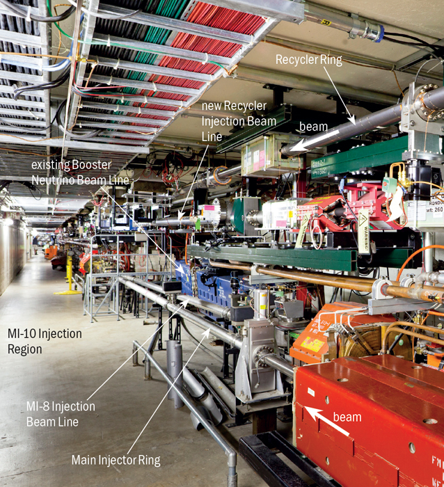
To use the Recycler for slip-stacking required a reconfiguration of the accelerator complex. A new injection beamline from the Booster to the Recycler had to be built (figure 3), since previously the only way to get protons into the Recycler was via the Main Injector. In addition, a new extraction beamline from the Recycler to the Main Injector was needed, as the aperture of the previous line was designed for the transfer of low-emittance, low-intensity antiproton beams. New 53 MHz RF cavities for the Recycler were installed to capture the protons from the Booster, slip-stack them and then transfer them to the Main Injector. New instrumentation had to be installed and all of the devices for cooling antiproton beams – both stochastic and electron cooling systems – and for beam transfer had to be removed.
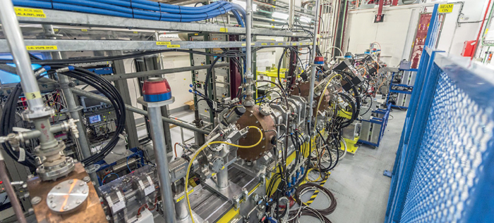
Figure 4 shows the new injection line from the Booster (figure 5) to the Recycler, together with the upgraded injection line to the Main Injector, the transfer line for the Booster Neutrino Beam programme, and the Main Injector and Recycler rings. During the shutdown, personnel removed more than 100 magnets, all of the stochastic cooling equipment, vacuum components from four transfer lines and antiproton-specific diagnostic equipment. More than 150 magnets, 4 RF cavities and about 500 m of beam pipe for the new transfer lines were installed. Approximately 300 km of cable was pulled to support upgraded beam-position monitoring systems, new vacuum installations, new kicker systems, other new instrumentation and new powered elements. Approximately 450 tonnes of material was moved in or out of the complex at the same time.
The NuMI target
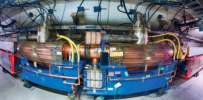
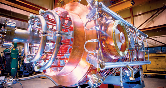
To prepare for a 700 kW beam, the target station for the NuMI facility needed upgrades to handle the increased power. A new target design was developed and fabricated in collaboration with the Institute for High Energy Physics, Protvino, and the Rutherford Appleton Laboratory, UK. A new focusing horn was installed to steer higher-energy neutrinos to the NOvA experiment (figure 6). The horn features a thinner conductor to minimize ohmic heating at the increased pulsing rate. The water-cooling capacity for the target, the focusing horns and the beam absorber were also increased.
With the completion of the shutdown, commissioning of the accelerator complex is underway. Operations have begun using the Main Injector, achieving 250 kW on target for the NuMI beamline and delivering beam to the Fermilab Test Beam Facility. The reconfigured Recycler has circulated protons for the first time and work is underway towards full integration of the machine into Main Injector operations. The neutrino experiments are taking data and the SeaQuest experiment will receive proton beam soon. Intensity and beam power are inceasing in all of the machines and the full 700 kW beam power in the Main Injector should be accomplished in 2015.
As the first long shutdown since the start-up of the LHC continues, many teams at CERN are already preparing for future improvements in performance that were foreseen when the machine restarts after the second long shutdown, in 2019. The LHCb collaboration, for one, has recently approved the choice of technology for the upgrade of its Vertex Locator (VELO), giving the go-ahead for a new pixel detector to replace the current microstrip device.
The collaboration is working towards a major upgrade of the LHCb experiment for the restart of data-taking in 2019. Most of the subdetectors and electronics will be replaced so that the experiment can read out collision events at the full rate of 40 MHz. The upgrade will also allow LHCb to run at higher luminosity and eventually accumulate an order of magnitude more data than was foreseen with the current set-up.
The job of the VELO is to peer closely at the collision region and reconstruct precisely the primary and secondary interaction vertices. The aim of the upgrade of this detector is to reconstruct events with high speed and precision, allowing LHCb to extend its investigations of CP violation and rare phenomena in the world of beauty and charm mesons.
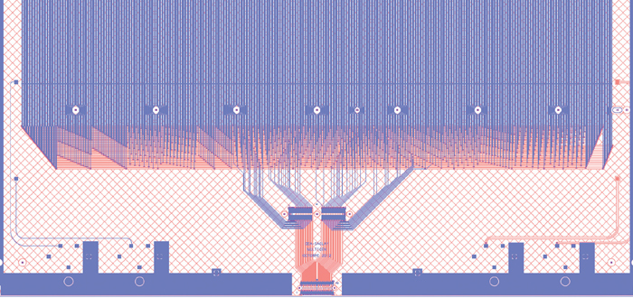
The new detector will contain 40 million pixels, each measuring 55 μm square. The pixels will form 26 planes arranged perpendicularly to the LHC beams over a length of 1 m (see figure). The sensors will come so close to the interaction region that the LHC beams will have to thread their way through an aperture of only 3.5 mm radius.
Operating this close to the beams will expose the VELO to a high flux of particles, requiring new front-end electronics capable of spitting out data at rates of around 2.5 Tbits/s from the whole VELO. To develop suitable electronics, LHCb has been collaborating closely with the Medipix3 collaboration. The groups involved have recently celebrated the successful submission and delivery of the Timepix3 chip. The VeloPix chip planned for the read-out of LHCb’s new pixel detector will use numerous Timepix3 features. The design should be finalized about a year from now.
An additional consequence of the enormous track rate is that the VELO will have to withstand a considerable radiation dose. This means that it requires highly efficient cooling, which must also be extremely lightweight. LHCb has therefore been collaborating with CERN’s PH-DT group and the NA62 collaboration to develop the concept of microchannel cooling for the new pixel detector. Liquid CO2 will circulate in miniature channels etched into thin silicon plates, evaporating under the sensors and read-out chips to carry the heat away efficiently. The CO2 will be delivered via novel lightweight connectors that are capable of withstanding the high pressures involved. LHCb will be the first experiment to use evaporative CO2 cooling in this way, following on from the successful experience with CO2 cooling delivered via stainless steel pipes in the current VELO.
All of these novel concepts combine to make a “cool” pixel detector, well equipped to do the job for the LHCb upgrade.
Modern physics experiments often require the detection of particles over large areas with excellent spatial resolution. This inevitably leads to systems equipped with thousands, if not millions, of read-out elements (strips, pixels) and consequently the same number of electronic channels. In most cases, it increases the total cost of a project significantly and can even be prohibitive for some applications.
In general, the size of the electronics can be reduced considerably by connecting several read-out elements to a single channel through an appropriate multiplexing pattern. However any grouping implies a certain loss of information and this means that ambiguities can occur. Sébastien Procureur, Raphaël Dupré and Stéphan Aune at CEA Saclay and IPN Orsay have devised a method of multiplexing that overcomes this problem. Starting from the assumption that a particle leaves a signal on at least two neighbouring elements, they built a pattern in which the loss of information coincides exactly with this redundancy of the signal, therefore minimizing the ambiguities of localization. In this pattern, two given channels are connected to several strips in such a way that these strips are consecutive only once in the whole detector. The team has called this pattern “genetic multiplexing” for its analogy with DNA, as a sequence of channels uniquely codes the particle’s position.
Combinatorial considerations indicate that, using a prime number p of channels, a detector can be equipped with at most p(p–1)/2+1 read-out strips. Furthermore, the degree of multiplexing can be adapted easily to the incident flux. Simulations show that a reduction in the electronics by a factor of two can still be achieved at rates up to the order of 10 kHz/cm2.
The team has successfully built and tested a large, 50 × 50 cm2 Micromegas (micro-pattern gaseous detector) with such a pattern, the 1024 strips being read out with only 61 channels. The prototype showed the same spatial resolution as a non-multiplexed detector (Procureur et al. 2013). A second prototype that is built from resistive-strip technology will be tested soon, to achieve efficiencies close to 100%.
The possibility of building large micro-pattern detectors with up to 30 times less electronics opens the door for new applications both within and beyond particle physics. In muon tomography, this multiplexing could be used to image large objects with an unprecedented accuracy, either by deflection (containers, trucks, manufacturing products) or by absorption (geological structures such as volcanoes, large monuments such as a cathedral roof). The reduction of the electronics and power consumption also suggests applications in medical imaging or dosimetry, where light, portable systems are required. Meanwhile, in particle physics this multiplexing could bring a significant reduction in the cost of electronics – after optimizing the number of channels with the incident flux – and simplifications in integration and cooling.
The interaction with plasma of ultra-high-peak-power lasers at the terawatt to petawatt level has the potential to generate large accelerating gradients of giga-electron-volts per metre. Laser-plasma acceleration could therefore be an important replacement for present technology. However, there are two formidable hurdles to overcome: a laser repetition rate that is limited to a few hertz leading to an average power of only a few watts and a dismal wall-plug efficiency of a fraction of a per cent. This twin technological challenge must be resolved if laser wakefield acceleration is to be considered for large-scale applications in science and society.
On 27–28 June, the International Coherent Amplification Network (ICAN) Consortium concluded its EU-supported 18-month feasibility study with a final symposium at CERN that was organized by Ecole Polytechnique, the University of Southampton, Fraunhofer IOF Jena and CERN. A major topic concerned progress with the novel laser architecture known as coherent amplification network (CAN), which could for the first time provide petawatt peak power at a repetition rate as high as 10 kHz. This corresponds to an average power in the megawatt range with an efficiency better than 30% and opens the door to many applications.
The ICFA-ICUIL Joint Task Force (JTF) produced a report noting that while the science of laser acceleration has matured, the technology for intense lasers is lagging behind
The symposium also looked at the path towards future laser-driven accelerators and colliders, applications in free-electron lasers and neutron/neutrino sources, as well as the laser search for the “dark fields” of dark matter and dark energy. Other topics included compact proton accelerators that could be used for accelerator-driven systems for nuclear energy or for hadron therapy, as well as the generation of γ-ray beams with a host of applications, from the identification of isotopes in exposed spent nuclear fuel – such as at Fukushima – to nuclear pharmacology.
The main paradigm currently driving fundamental high-energy physics is the high-energy charged-particle collider. To apply laser-acceleration methods to a future collider, the international communities involved in intense lasers and high-energy physics – in the form of the International Committee on Ultra-High Intensity Lasers (ICUIL) and the International Committee for Future Accelerators (ICFA), respectively – came together in 2009 to form a collaborative working group to study how best to proceed. The ICFA-ICUIL Joint Task Force (JTF) produced a report noting that while the science of laser acceleration has matured, the technology for intense lasers is lagging behind, specifically in the development of systems with a high repetition rate and high efficiency (Leemans et al. 2011).
The possibility of amplifying laser pulses to extreme energy and peak power not only offers a route to a more compact and cheaper way to perform high-energy physics, it could also open the door to a complementary research area that is underpinned by single-shot, high-field laser pulses – a new field of (laser-based) high-field fundamental physics (Tajima and Dawson 1979 and Mourou et al. 2006). To muster the support of the scientific community for this vision, the International Center on Zetta-Exawatt Science and Technology (IZEST) was set up in 2011 and now has 23 associated institutes worldwide.
The ICAN project
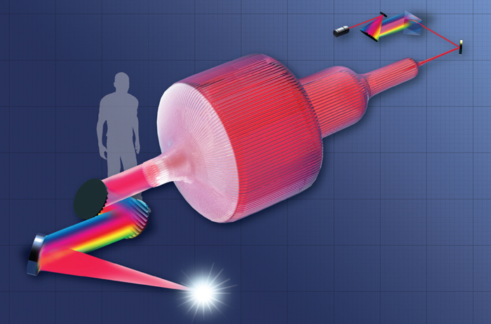
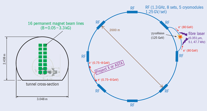
Stimulated by the JTF’s report, members of IZEST set up the ICAN project, which involves a total of 16 institutes including Ecole Polytechnique, the University of Southampton, Fraunhofer IOF Jena and CERN as beneficiaries with a further 13 institutes participating as experts. Starting in October 2011, ICAN began research on the development of the fibre-laser-based CAN concept. Here, pulses from thousands of fibre lasers – built on technology that was originally developed for the telecommunications industry and each capable of producing low-energy pulses efficiently and at a high repetition rate – are coherently added to increase the average power and pulse energy linearly as the number of fibres increases (figure 1). The ICAN project has shown that this architecture can provide a plausible path towards the necessary conditions for a high-energy collider based on a laser accelerator, so answering the challenge that was posed by the JTF report. The fibre laser offers excellent efficiency (>30%) thanks to laser-diode pumping and provides a much larger surface cooling area, therefore making operation at high average power possible.
The most stringent requirement is to phase all of the lasers within a fraction of a wavelength. This originally seemed insurmountable but a preliminary proof of concept that was discussed earlier this year in Nature Photonics suggests that tens of thousands of fibres can be controlled to provide a laser output that is powerful enough to accelerate electrons to energies of several giga-electron-volts at a 10 kHz repetition rate. This is an improvement of at least 10,000 times on today’s state-of-the-art (Mourou et al. 2013). Furthermore, experiments have demonstrated the feedback control of the phase and timing of pulses from each fibre to the attosecond precision necessary for coherent addition. This means that the spatial profile of the overall laser pulse can be delicately controlled to provide a precise beam shape – a highly desirable feature for laser accelerators.
Immediately after the publication of the article in Nature Photonics, the group at Fermilab re-launched the concept of a photon (γ–γ) collider for a Higgs factory, using the CAN laser as the source of low-energy photons to generate high-energy γ rays through inverse Compton scattering from two electron beams (figure 2). Such a collider would have a lower beam energy than the equivalent electron–positron collider and less noise (Chou et al. 2013). The required repetition rate is around 50 kHz, within the reach of CAN technology.
Fundamental physics via high fields
While a photon collider would study Higgs physics and other high-energy phenomena, copious coherent photons from the CAN lasers could also provide a new opportunity to look for undetected “dark fields” that are associated with low-energy dark matter (axion-like particles, for example) and dark energy (Tajima and Homma 2012). The use of three distinct parallel lasers with huge numbers of photons could allow sensitive detection of possible dark fields. The basic idea is akin to degenerate four-wave mixing, well known in traditional nonlinear optics but in this case probing the vacuum, whose possible nonlinear constituent is so weak that it has appeared “dark” until now. Since the parallel injection of lasers can make their beat frequency particularly low, the range of detectable masses is extremely low – down to nano-electron-volts – compared with orthodox high-energy physics experiments. The extremely high equivalent luminosity is also unusual. Because of the coherence of the photons, the luminosity of the events is proportional to the triple products of the numbers of photons from the three lasers – N1N2N3. If the laser has 10 kJ energy, the Ni here can each be as large as 1023. On the other hand, the luminosity of a charged-particle collider is proportional to NaNb, where a and b represent the two beams and these Nj are typically around 1010. The two products that determine the luminosity of each “collider” therefore differ by as much as 50 orders of magnitude.
Laser-driven acceleration processes, laser wakefield acceleration and the related physical processes might also appear in nature, as demonstrated by the recent realization that the accretion disc of a supermassive black hole and its associated jets could be the theatre for extreme high-energy cosmic-ray acceleration up to 1021 eV and accompanying γ-ray emission (Ebisuzaki and Tajima 2013). The disruptive magnetic activities of the disc give rise to the excitation of huge Alfvén waves and the mode-converted electromagnetic waves created in the jet are capable of accelerating ions to extreme energies via a process that is similar to laser acceleration. The coherence of the relativistic waves and particles implies a fundamental similarity between terrestrial and celestial wakefield acceleration processes. It is hoped that one day celestial-type wakefields might be achieved by a similar physical process but on different scales on Earth.
Applications in society
Turning to more earthly issues, the CAN fibre laser opens up many doors to challenging issues in society. With high average power at the same time as high peak power, along with high efficiency and inherent controllability, the CAN source is applicable to many new areas, of which the following are a few examples.
Laser acceleration of protons would provide compact installations compared with conventional accelerators, which could lead to compact proton-therapy accelerators (Habs et al. 2011). As the intensity of the laser becomes highly relativistic and the dynamics of proton acceleration become more relativistic, the acceleration mechanism becomes more efficient and the beam quality improves (Esirkepov et al. 2004). It then becomes plausible to produce an efficient, compact proton source in the relativistic regime.
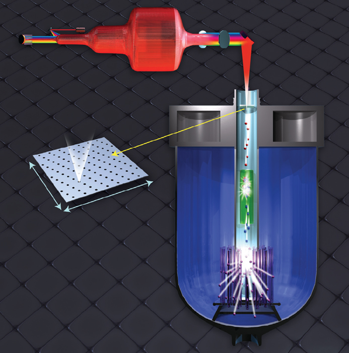
Laser-driven compact proton beams could also act as the source of neutrons for accelerator-driven systems and accelerator-driven reactors for nuclear energy (figure 3). The high-fluence CAN laser offers the potential for highly efficient compact neutron sources that would be less expensive than those based on conventional methods (Mourou et al. 2013).
Just as in the case of the photon collider but at lower energies, the CAN laser can produce copious γ rays with specified energy in a well defined direction. Such γ-ray sources are useful for detection in nuclear physics, such as in isotopic determination via nuclear resonance fluorescence. Since a CAN-driven γ-ray source could be compact enough to be portable, it could be used for isotopic diagnosis of exposed spent nuclear fuel – as at Fukushima – without contact or proximity. Other industries – auto, chemical, mechanical, medical, energy, etc – have the need for high-fluence, high-efficiency short-pulse lasers. One example is nuclear pharmacology. Since a CAN source produces γ rays (and so neutrons) of specific energy, it can be used to create specific isotopes of nuclei that are known to be useful for medical purposes (Habs et al. 2011).
The future looks bright for fibre lasers – not only in high-energy physics but in many applications for society.
Micropattern gaseous detectors (MPGDs) are the modern heirs of multiwire proportional counter (MWPC) planes, with the wires replaced by microstructures that are engraved on printed-circuit-like substrates. An idea that was first proposed by Anton Oed in 1988, it was the invention of stable amplification structures such as the micromesh gaseous structure (Micromegas) by Ioannis Giomataris in 1996 and the gas electron multiplier (GEM) by Fabio Sauli in 1997 that triggered a boom in the development and applications of these detectors. It was as a consequence of this increasing activity that the series of international conferences on micropattern gaseous detectors was initiated, with the first taking place in Crete in 2009 followed by the second meeting in Kobe in 2011.
The third conference – MPGD2013 – moved to Spain, bringing more than 125 physicists, engineers and students to the Paraninfo building of the Universidad de Zaragoza during the first week of July. The presentations and discussions took place in the same room that, about a century ago, Santiago Ramón y Cajal – the most prominent Spanish winner of a scientific Nobel prize – studied and taught in. The Paraninfo is the university’s oldest building and its halls, corridors and stairs provided an impressive setting for the conference. The streets, bars and restaurants of Zaragoza – the capital of Aragon – were further subjects for the conference participants to discover. After an intense day of high-quality science, lively discussions often continued into the evening and sometimes late into the night, helped by a variety of tapas and wines.
The wealth of topics and applications that were reviewed at the conference reflected the current exciting era in the field. Indeed, the large amount of information and number of projects that were presented make it difficult to summarize the most relevant ones in a few lines. The following is a personal selection. Readers who would like more detail can browse the presentations that are posted on the conference website, including the excellent and comprehensive conference-summary talk given by Silvia Dalla Torre of INFN/Treiste on the last day.
The meeting started with talks about experiments in high-energy and nuclear physics that are using (or planning to use) MPGDs. Since the pioneering implementation of GEM and Micromegas detectors by the COMPASS collaboration at CERN – the first large-scale use of MPGDs in high-energy physics – they have spread to many more experiments. Now all of the LHC experiment collaborations plan to install MPGDs in their future upgrades. The most impressive examples, in terms of detector area, are the 1200 m2 of Micromegas modules to be installed in the muon system of ATLAS and the 1000 m2 of GEM modules destined for the forward muon spectrometer of CMS. These examples confirm that MPGDs are the technology of choice when large areas need to be covered with high granularity and occupancy in a cost-effective way. These numbers also imply that transferring the fabrication know-how to industry is a must. A good deal of effort is currently devoted to industrialization of MPGDs and this was also an important topic at the conference.
MPGDs have found application in other fields of fundamental research. Some relevant examples that were discussed at the conference included their use as X-ray or γ detectors or as polarimeters in astrophysics, as neutron or fission-fragment detectors, or in rare-event experiments. Several groups are exploring the possibility of developing MPGD-based light detectors – motivated greatly by the desire to replace large photo-multiplier tube (PMT) arrays in the next generation of rare-event experiments. Working at cryogenic temperatures – or even within the cryogenic liquid itself – is sometimes a requirement. Large-area light detectors are also needed for Cherenkov detectors and in this context presentations at the conference included several nice examples of Cherenkov rings registered by MPGDs. Several talks reported on applications beyond fundamental research, including a review by Fabrizio Murtas of INFN/Frascati and CERN. MPGDs are being used or considered in fields as different as medical imaging, radiotherapy, material science, radioactive-waste monitoring and security inspection, among others.
An important part of the effort of the community is to improve the overall performance of current MPGDs, in particular regarding issues such as ageing or resilience to discharges. This is leading to modified versions of the established amplification structures of Micromegas and GEMs and to new alternative geometries. Some examples that were mentioned at the conference are variations that go under the names of μ-PIC, THGEM, MHSP or COBRA, as well as configurations that combine several different geometries. In particular, a number of varieties of thick GEM-like (THGEM) detectors (also known as large electron multipliers, or LEM) are being actively developed, as Shikma Bressler of the Weizmann Institute of Science described in her review.
Many of the advances that were presented involve the use of new materials – for example, a GEM made out of glass or Teflon – or the implementation of electrodes with resistive materials, the main goal being to limit the size and rate of discharges and their potential damage. Advances on the GridPix idea – the use of a Micromegas mesh post-processed on top of a Timepix chip – also go in the direction of adding a resistive layer to limit discharges and attracted plenty of interest. Completely new approaches were also presented, such as the “piggyback Micromegas” that separates the Micromegas from the actual readout by a ceramic layer, so that the signal is read by capacitive coupling and the readout is immune to discharges.
Several senior members gave advice to the new generation of MPGD researchers and proposed a toast to them
The presence of CERN’s Rui de Oliveira to review the technical advances in MPGD fabrication techniques and industrialization is already a tradition at these meetings. Current efforts focus on the challenges presented by projects that require GEM and Micromegas detectors with larger areas. Another tradition is to hear Rob Veenhof of Uludağ University and the RD51 collaboration review the current situation in the simulation of electron diffusion, amplification and signal detection in gas, as well as the corresponding software tools. Current advances are allowing the community to understand progressively the performance of MPGDs at the microphysics level. Finally, although electronics issues were present in many of the talks, the participants especially enjoyed a pedagogical talk by CERN’s Alessandro Marchioro about the trends in microelectronics and how they might affect future detectors in the field. These topics were studied in more detail in the sessions of the RD-51 collaboration meeting that came after the conference at the same venue. Fortunately, there was the opportunity to relax before this following meeting, with a one-day excursion to the installations of the Canfranc Underground Laboratory in the Spanish Pyrenees and St George’s castle in the town of Jaca.
The vitality of the MPGD community resides in the relatively large number of young researchers who came to Zaragoza eager to present their work as a talk or as one of the 40 posters that were displayed in the coffee and lunch hall during the week. Three of those young researchers – Michael Lupberger of the University of Bonn, Diego González-Díaz of the University of Zaragoza and Takeshi Fujiwara of the University of Tokyo – received the Charpak Prize to reward their work. This award was first presented at MPGD2011 in Japan and the hope is that it becomes formally established in the MPGD community on future occasions.
Time will tell which of the many ideas that are now being put forward will eventually become established but the creativity of the community is remarkable and one of its most important assets. References to this creativity – and to the younger generation of researchers who foster it – were recurrent throughout the conference. At the banquet, by the Ebro riverbank under the shadow of the tall towers of the Basílica del Pilar, several senior members gave advice to the new generation of MPGD researchers and proposed a toast to them – a blessing for the field.
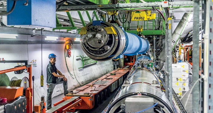
Work during the current long shutdown (LS1) of CERN’s accelerator complex is making good progress since starting in February this year. Of the LHC’s 1232 dipoles, 15 are being replaced together with three quadrupole-magnet assemblies. By the beginning of September, all of the replacement magnets had been installed in their correct positions and were awaiting reconnection.
Moving the heavy magnets requires specially adapted cranes and trailers. Moreover, there is only one access shaft – made for the purpose during the installation phase – that is wide enough to lower dipoles, each 15 m long and weighing 35 tonnes, to the tunnel. Underground, a specialized trailer carried the replacement magnets to where they were needed. Sensors fitted below the trailer enabled it to “read” and follow a white line along the tunnel floor.
Back in April, the first Superconducting Magnets and Circuits Consolidation (SMACC) teams began work in the tunnel. They are responsible for opening the interconnects between the magnets to lay the groundwork for the series of operations needed for the consolidation effort on the magnet circuits.
The cables of superconductor that form the LHC’s superconducting dipoles and quadrupoles carry a current of up to 11,850 A. The SMACC project was launched in 2009 to avoid the serious consequences of electric arcs that could arise from discontinuities in the splices between the busbars of adjacent magnets (CERN Courier September 2010 p27). The main objective is to install a shunt – a small copper plate that is 50 mm long, 15 mm wide and 3 mm thick – on each splice, straddling the main electrical connection and the busbars of the neighbouring magnets. Should a quench occur in the superconducting cable, the current will pass through the copper part, which must therefore provide an unbroken path. In total, more than 27,000 shunts will have to be put in place – an average of one every three minutes for the teams of technicians, who work on a number of interconnects in parallel.
By the end of summer, three quarters of the interconnect bellows between magnets had been opened. Almost all of the SMACC consolidation activities had been completed in sector 5-6 and the first bellows were being closed again ready for testing. In sector 6-7, the installation of the shunts was being completed and the procedure was starting in sector 7-8. The aim is for completion of the task in July 2014.
After more than a year of upgrades, Fermilab’s revamped accelerator complex is ready to send beam to its suite of fixed-target experiments, which now includes the new NOvA neutrino detector in northern Minnesota, 810 km north of the laboratory.
On 30 July, a beam of protons passed through the main injector for the first time since April 2012. With a circumference of 3.3 km, this synchrotron is the final stage of acceleration in the Fermilab accelerator complex, propelling protons from 8 to 120 GeV. Prior to the shutdown, the machine achieved a beam power of about 350 MW. The shutdown work paves the way to increase this to 700 MW.
The majority of this beam power from the main injector will be used to make neutrinos for the NOvA, MINOS and Minerva experiments. The first neutrinos were delivered on 4 September. A smaller fraction of the proton beam will go to the SeaQuest experiment and Fermilab’s Test Beam Facility. In the future, the main injector will also provide beam for the planned Muon g-2 and Mu2e experiments and the Long-Baseline Neutrino Experiment.
Following the revamp, Fermilab’s chain of accelerators begins with a new ion source and radio-frequency quadrupole (RFQ) to create a beam of negatively charged hydrogen ions, which are accelerated by the RFQ to an energy of 750 keV. The ions then enter the linac, which accelerates the particles to 400 MeV and sends them into the booster, where the particles pass through a foil that strips off the electrons and yields a proton beam. The upgraded booster, which accelerates protons to 8 GeV, now features solid-state RF stations and a few refurbished RF cavities. Once all of the RF cavities have been refurbished – in about two years from now – it will be able to operate at a repetition rate of up to 15 Hz. This work is part of the laboratory’s Proton Improvement Plan.
A major component of the upgraded accelerator complex is the revamped Recycler storage ring, which will play a major role in achieving higher beam power in the main injector. In the past, the Recycler stored 8 GeV antiprotons for the Tevatron collider. The Recycler is now being used for slip-stacking 8 GeV protons and as a result the main injector can deliver beam to Fermilab’s neutrino experiments every 1.3 s. Previously, it could send beam every 2.2 s only.
To provide the best experiences, we use technologies like cookies to store and/or access device information. Consenting to these technologies will allow us to process data such as browsing behavior or unique IDs on this site. Not consenting or withdrawing consent, may adversely affect certain features and functions.
Functional
Always active
The technical storage or access is strictly necessary for the legitimate purpose of enabling the use of a specific service explicitly requested by the subscriber or user, or for the sole purpose of carrying out the transmission of a communication over an electronic communications network.
Preferences
The technical storage or access is necessary for the legitimate purpose of storing preferences that are not requested by the subscriber or user.
Statistics
The technical storage or access that is used exclusively for statistical purposes.The technical storage or access that is used exclusively for anonymous statistical purposes. Without a subpoena, voluntary compliance on the part of your Internet Service Provider, or additional records from a third party, information stored or retrieved for this purpose alone cannot usually be used to identify you.
Marketing
The technical storage or access is required to create user profiles to send advertising, or to track the user on a website or across several websites for similar marketing purposes.