Ken Takayama describes recent tests at KEK that have demonstrated induction acceleration in a proton synchrotron.
For half a century, the synchrotron has been the workhorse of high-energy particle physics, from its first use with external beams to the modern particle colliders. The basic principle is to use the electric field in a radio-frequency (RF) wave to accelerate charged particles, the frequency varying to keep in time with particles on a constant trajectory through a ring of guiding magnets.
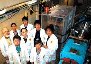
Now a team has demonstrated a different way of accelerating the protons in tests at the proton synchrotron (PS) at KEK, the Japanese High Energy Accelerator Research Organization in Tsukuba. For the first time, a bunch of protons in the synchrotron has been accelerated by an induction method (K Takayama et al. 2004). The technique may overcome certain effects that normally limit the intensity achieved in a synchrotron beam, and could prove to be an important advance for future proton colliders.
The concept of an “induction synchrotron” was first proposed about five years ago by the author and Jun-ichi Kishiro of KEK and the Japan Atomic Energy Research Institute (Takayama and Kishiro 2000). The idea was to overcome shortcomings of the RF synchrotron, in particular the limited longitudinal phase-space available for the acceleration of charged particles – in other words the distribution in energy and position around the ring of the particles being accelerated. In a conventional synchrotron, the particles are accelerated when they pass through an RF cavity, a device that contains the oscillating radio wave. The electric field naturally concentrates the particles into bunches in the direction of motion (i.e. longitudinally).
In the induction synchrotron, however, the accelerating devices are replaced with induction devices, in which a changing magnetic field produces the electric field to accelerate the particles. The basic device is a ferromagnetic ring, or core, through which the particles pass. A pulsed voltage sets up a magnetic field, and the changing magnetic flux in turn induces an electric field along the axis of the core. The induction-acceleration technique was first developed in the late 1960s and has a range of applications in linear accelerators, but the recent KEK experiment was the first time it was applied in a circular machine.
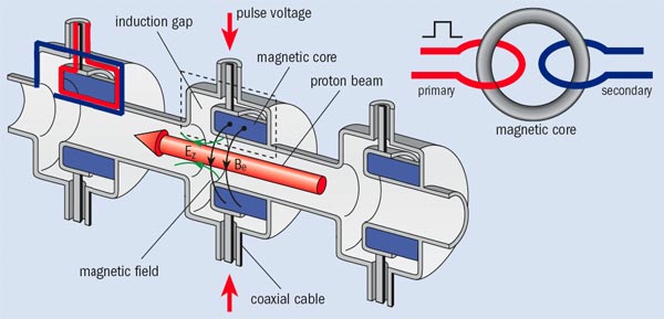
The system consists basically of an induction cavity with three cells driven by a pulse modulator as shown in figure 1. The cells developed for the experiment, which are rather like one-to-one transformers, use a nanocrystalline alloy as the magnetic-core material. The pulse modulator is connected to the acceleration cavity through a 40 m long transmission cable to keep the modulator far from the accelerator, where its solid-state switching elements would be exposed to high radiation. A matching resistance at the driver end reduces reflections. The pulse modulator can be operated in various modes from burst to 1 MHz continuous-wave via a system controlled by a digital signal processor (DSP).
In July 2004 the system was demonstrated to be capable of generating a step-pulse of 2 kV and a peak current of 18 A at 1 MHz with a duty cycle of 50%. It was then installed in the KEK PS in September, ready to test induction acceleration.
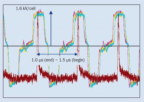
For the experiment a single bunch of 6 x 10¹¹ protons was injected into the main ring at 500 MeV, trapped in an RF bucket and accelerated up to 8 GeV. The aim was that the RF would simply capture the beam bunch while the induction voltage provided the acceleration. The timing of the master trigger for the pulse modulator was adjusted via the DSP so that the signal from the bunch stayed around the centre of the induction voltage pulse for the entire accelerating period. Figure 2 shows typical waveforms of the induction voltage signals for the three cells, plus the bunch signals.
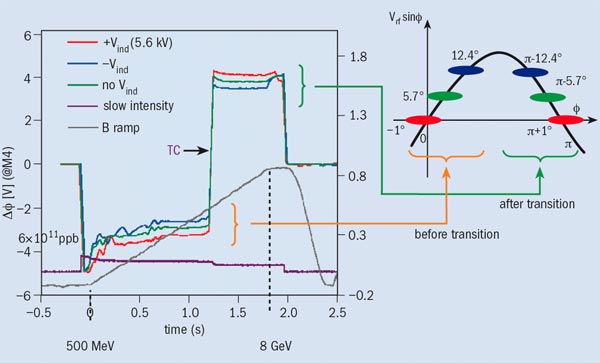
To confirm the induction acceleration, the relative phase difference Δφ between the RF and the bunch centre was measured for three cases: with the RF voltage alone; with both the RF and positive induction voltages for acceleration; and with the RF and negative induction voltages. With both the RF and induction voltages, the centre of the bunch receives an effective voltage per turn of V = Vrfsinφ + Vind’ where Vrf and Vind are the RF and the induction voltages respectively, and φ is the position of the bunch in the RF phase. A value for V of 4.8 kV is required for the RF bunch to follow the linearly ramping bending field of the synchrotron magnets.
Figure 3 shows the temporal evolutions of the measured phase for three cases. The results are in close agreement with the prediction from the equation for the voltage per turn of φ = 5.7°,-1.0° and 12.4° for the three cases, with Vrf = 48 kV and Vind = 5.6 kV for the respective cases. The position of the proton bunch relative to the RF voltage for each case is also shown schematically on the right in the same figure. The plots indicate the successful acceleration of the bunch beyond the transition energy. This is the critical energy characteristic of a strong-focusing synchrotron at which the particles’ revolution period becomes almost independent of energy and the stable phase position switches from one side of the RF pulse to the other, as indicated in figure 3.
These results are the first step in demonstrating the feasibility of an induction synchrotron, which could have important implications for future machines. A significant advantage of the induction technique is that the functions of acceleration and longitudinal focusing are achieved separately. This is not the case in the RF synchrotron where the gradient in the electric field provides the longitudinal confinement. In an induction machine voltage pulses of opposite sign separated by some time period can provide the longitudinal focusing forces. A pair of barrier-voltage pulses should work in a similar way to the RF barrier, which has been demonstrated at Fermilab, Brookhaven National Laboratory and CERN.
Separating the acceleration and focusing functions in the longitudinal direction brings about a significant freedom of beam-handling compared with conventional RF synchrotrons. In particular, it offers a means of forming a “superbunch”: an extremely long beam bunch with a uniform density that would be most attractive in future hadron colliders and proton drivers for neutrino physics. In addition, crossing the transition energy without any longitudinal focusing seems to be feasible, and this could substantially mitigate undesired phenomena, such as bunch-shortening from non-adiabatic motion and microwave instabilities. The next step at KEK will be to test the barrier-voltage concept, proceeding further towards the formation of a superbunch in an induction synchrotron.
Further reading
K Takayama et al. 2004 in press Phys. Rev. Lett. http://www.arxiv.org/pdf/physics/0412006.
K Takayama and J Kishiro 2000 Nucl. Inst. Meth. in Phys. Res. A 451 304.


