Klystron modulators are key elements in free electron lasers. They provide high-voltage pulses to bias klystron tubes with energies of several hundred joules. Amplitude variations directly affect the gain and phase of amplified RF pulses and therefore the accelerating fields created by RF cavities. A huge effort is put into minimising these variations with both klystron modulators and RF pulse regulation.
For machines such as the SwissFEL (Swiss Free Electron Laser), the required HV pulse stability is 15 ppm (parts per million). Stability is calculated from measurements of 100 consecutive pulses taken at a repetition rate of 100 Hz as the relative standard deviation of gated averages with respect to a mean pulse amplitude. The measurement gate is located around the maximum plateau of the pulse, the so-called flat-top region, during which the RF pulse is fired.

A common technique for measuring such small variations involves pulse offsetting and magnification of the flat-top region in order to achieve a sufficient quantisation resolution. However, signal conditioning requires low-noise analogue electronics in the form of summing amplifiers and clippers with sufficient bandwidth and settling time. Such a set-up has so far involved the use of an external differential amplifier for signal conditioning and a high-end scope with statistical analysis functionality. The resolution of this set-up makes it possible to measure stability down to around 7 ppm, and it is mounted on a trolley so that it can be shared between RF stations.
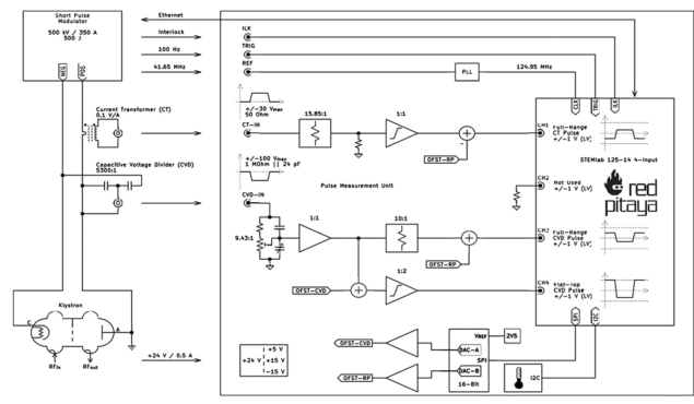
Starting as an apprentice project, the aim was to consolidate such a bulky and extensive set-up into an embedded unit that could be integrated into any pulse modulator cabinet, allowing permanent live monitoring of pulse stability. As a versatile data-acquisition system with open source firmware / software and small size, the Red Pitaya device is a perfect fit for this application. Figure 1 shows the block diagram of how a Red Pitaya STEMlab 125-14 4-input board, connected to a signal conditioning board developed at PSI, is used to measure the pulse stability of klystron modulators.

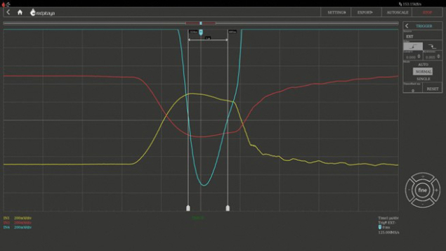
Pulse current and voltage are measured simultaneously, while only the voltage signal is used for the stability statistics. The required pulse offset voltage is automatically set by a precision 16-bit DAC before the statistics are calculated. There is a gain factor of 20 (26 dB) between the full range pulse voltage on channel 3 and the flat-top voltage on channel 4, giving a theoretical increase in resolution of 4.3 bits. In principle, this gain can be increased further to give an even higher resolution, but in practice the pulse is not purely rectangular but has a dynamic range due to pulse droop and non-flatness. Figure 2 shows how real waveforms might look in operation. The yellow trace shows the pulse current, while the red and blue traces show the full-range and magnified flat-top pulse voltages, respectively.
The set-up presented here was able to measure pulse stability of 7–8 ppm in operation, with a resolution limit of 5–6 ppm at a 1 µs gate length and 67% of ADC full scale.

The software running on the Red Pitaya is built around the standard C API and includes the OPC-UA stack from open62541.org to allow communication and data transfer via the server and client approach. The integration into our control system environment (EPICS) is currently on-going.
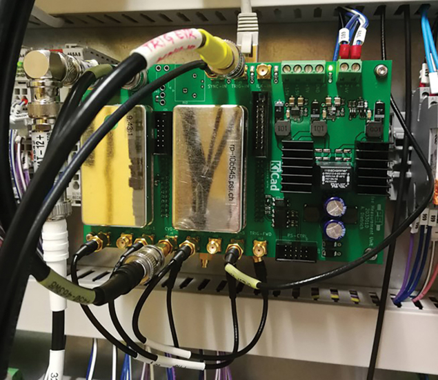
The complete assembly is called a Pulse Measurement Unit (PMU), and it offers many additional features such as the regulation of a high-voltage charging power supply, interfacing with opto-isolated IOs and a low-jitter PLL in order to lock external synchronisation frequencies to generate a synchronised ADC clock. With an overall size of 160 x 100 mm, the unit fits easily in a Eurocard rack or can be mounted on a DIN rail, as shown in Figure 3.
Velika pot 21, 5250
Solkan, Slovenia
Tel +386 30 322 719
E-mail nicu.irimia@redpitaya.com
www.redpitaya.com


