With construction of the Super Proton Synchrotron – known simply as the “400 GeV machine” – in full swing, the May 1975 issue of the Courier published a progress report on its vacuum and radio-frequency systems.
Things are obviously hotting up in the construction of the 400 GeV proton synchrotron, the SPS. With completion of the ring not much more than a year away, there is new information every month concerning the progress of installation. This time the vacuum system and the radio-frequency acceleration system have passed two important milestones.
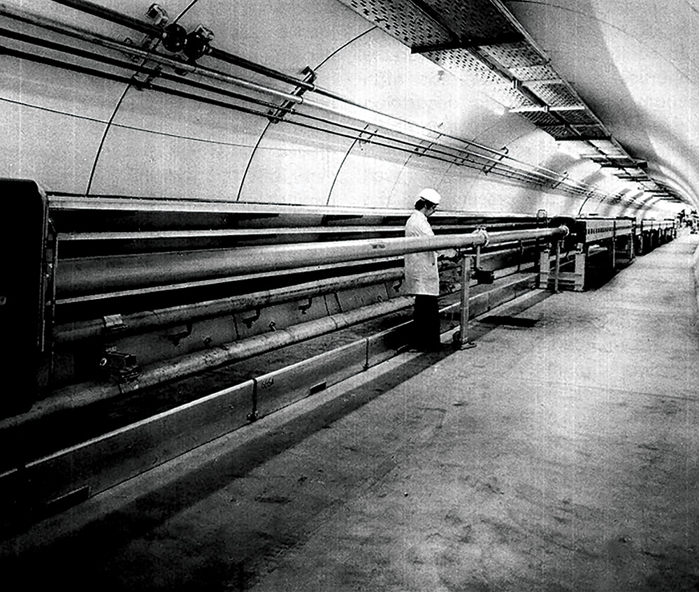
Assembly and testing on the vacuum chamber and the pumping stations in the SPS tunnel began last November and the work has continued at about the rate at which the magnets have been installed – 32 m per day, equivalent to one half-period. By now a tenth of the full system, including beam transfer lines, has been evacuated and held under vacuum for a month.
At the beginning of February, a 550 m length of the vacuum chamber in sextant 3 was pumped down. The pressure was taken to the region of 10–5 torr by three roughing pump stations fitted with vane and turbo-molecular pumps. At this stage, the control computer in auxiliary building No. 3 brought in forty-one ion pumps with a capacity of 25 l/s, distributed along the length of the vacuum pipe.
The time involved in reducing the pressure from atmospheric to the nominal operating pressure of the SPS – 3 × 10⁻⁷ torr – in this first pump down, was sixteen hours. A pressure of 1 × 10⁻⁷ torr was reached in forty-five hours.
It was then necessary to open up the chamber. The second pump down gave the nominal pressure after only five hours. In March, a further 420 m section was pumped with the same success. After a month under vacuum, this 970 m length is at 1 × 10⁻⁸ torr.
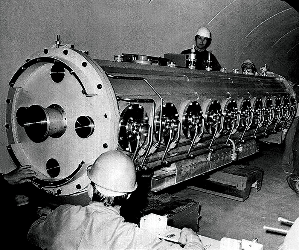
Two sections of one of the r.f. accelerating cavities have now been installed in the SPS tunnel and have successfully undergone vacuum tests. Each cavity is some 20 m long with five tank sections and the machine will have two cavities located in straight section No. 3.
The five sections for the first cavity are now at CERN. Some work has to be carried out on them before they are taken down to the tunnel – the trickiest job being the fitting of the drift tubes. There are eleven in each section and they have to be aligned with great precision. Allowance must be made for any irregularity in the shape of the tank and the length of the drift tube bars has to be adjusted before they are welded and brazed to the mounting blocks which make contact with the tank walls.
The coaxial lines and couplers which feed the power to the cavities in the tunnel are already in place. The lines, some 80 m long, go up to the power amplifiers in auxiliary building No. 3. Cooling pipes are also installed as are the terminating loads which absorb the r.f. power once it has passed through the cavities.
All that remains to be done in the tunnel is to install and connect up the tank sections. They must be aligned very accurately so that the intermediate seals remain completely vacuum-tight and allow the cavity’s 500 kW of r.f. power at 200 MHz to be properly conducted all the way around the tank. The sections rest on special supports which are designed to absorb any distortion caused by temperature rise in the cavities during operation.
The last three sections of the first cavity will be taken down to the tunnel at the rate of one every three weeks and the cavity will be completed towards the middle of June. The second cavity will be installed in Autumn.
- This article was adapted from text in CERN Courier vol. 15, May 1975, pp156–158