Techniques to shrink the beams of the heaviest ions ever used in a collider.
In May this year, the Relativistic Heavy Ion Collider (RHIC) at Brookhaven National Laboratory (BNL) finished its first run with beams of uranium ions – the heaviest ions ever used in a collider. Heavy ions contain large numbers of protons and neutrons and, when colliding at high energies, they create quark–gluon plasma, the state of matter that probably existed at the dawn of the universe. Not only was this the first time that uranium ions have been used in a particle collider, it was also the first time that the complete bunched-beam stochastic cooling system was used at RHIC, allowing cooling in the longitudinal, vertical and horizontal planes in both of the collider’s interlaced magnet rings.
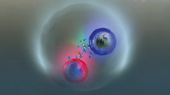
Uranium ions are now available at RHIC courtesy of the recently commissioned electron-beam ion source (EBIS). Physicists at the STAR and PHENIX experiments are particularly interested in uranium nuclei because of their prolate shape, more like a rugby ball than a sphere. Some of these nuclei will collide along their long axes, creating a quark–gluon plasma denser than the plasma discovered and now routinely created at RHIC in collisions of gold nuclei, which are more spherical. Some nuclei will collide with their long axes parallel, although perpendicular to their directions of motion. This arrangement creates a quark–gluon plasma with an oblong cross-section but without the strong magnetic field generated by grazing incidence collisions of spherical nuclei. Both of these possibilities make uranium–uranium collisions a new tool for studying quark–gluon plasma, adding to the toolbox that is currently available at both RHIC and the LHC.
A hadron-collider ‘first’

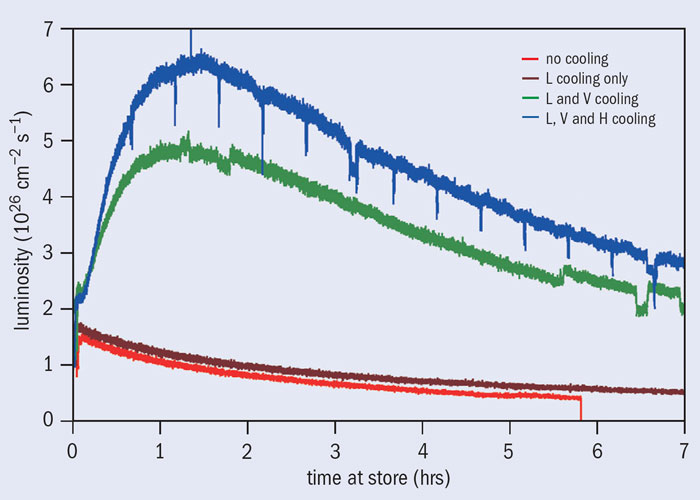
The amount of data delivered to the STAR and PHENIX experiments in the three-week exploratory run was increased five-fold by stochastic cooling, a feedback technique that shrinks the ion beams while they are colliding. This technique was developed at RHIC by a team that included Mike Blaskiewicz, Mike Brennan and Kevin Mernick (Blaskiewicz et al. 2010). The cooling is so strong that the beam size is reduced by half after an hour of storage time (figure 1) and the peak luminosity – or collision rate – rises to three times its initial value (figure 2). This has never been achieved in a hadron collider before. With a re-optimized lattice and stochastic cooling, no ions were lost by any mechanism other than through the uranium–uranium collisions themselves, which is also a first for a hadron collider.
In stochastic cooling, invented by Simon van der Meer and first demonstrated at CERN’s Intersecting Storage Rings in 1975, random fluctuations of particle distributions are detected and corrected for. The result is smaller and smaller distributions. The technique involves sending a signal from a pickup at one location to activate a kicker to correct the same bunch at a point further round the ring. While stochastic cooling was and is used in a number of low-energy storage rings, RHIC is the first collider with operational stochastic cooling. The procedure was first demonstrated in 2006 using a low-intensity proton bunch with 109 particles. Operational longitudinal cooling of gold ions in one of RHIC’s two rings was demonstrated the following year. Since then, both the Blue ring (clockwise) and the Yellow ring (anticlockwise) have been fitted with horizontal, vertical and longitudinal cooling, with full 3D cooling now available.
From pickup to kicker
The detection of fluctuations of distributions with high numbers of particles requires bandwidths in the gigahertz range. At RHIC, the ion beams at storage energy are composed of bunches of 5 ns full-width, separated by 107 ns. Cooling times of about 1 hour are obtained with a system bandwidth of 3 GHz and optimal kicker voltages of typically 3 kV. To reduce the microwave power required, a set of kicker cavities with a bandwidth of only 10 MHz has been adopted to take advantage of the bunch spacing. Each kicker consists of 16 cavities. Therefore, with three cooling planes there are 96 cavities in all for the two rings. The systems in the two rings are quite similar, so the following describes only the set-up for the Blue ring.
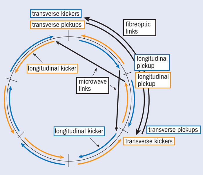
Image credit: BNL.
The longitudinal pickup is located in the 2 o’clock straight section (figure 3). Before the pickup signal is transmitted, it is first put through a traversal filter that repeats the signal 16 times to stretch it, with output S1(t) = S0(t)+S0(t–τ)+ … +S0(t–15τ) and τ = 5.000 ns. The effect of the filter, which is a key feature of the system at RHIC, is to maintain all of the information in the 5-ns-long bunch core while reducing the peak signal. This, in turn, lightens the load on the specially adapted commercial microwave link that is used to send the signal to the longitudinal kicker in the 4 o’clock straight section of the Blue ring. There, a one-turn filter is applied, where S2(t) = S1(t)–S1(t–Trev) with the revolution period Trev accurate to better than 1 ps. This filter ensures that the kick to the beam is proportional to the rate at which the beam is changing, similar to a viscous damping force being proportional to the velocity of a particle, not its position. The traversal filter causes the spectrum of the signal to have peaks of width 10 MHz separated by 200 MHz.
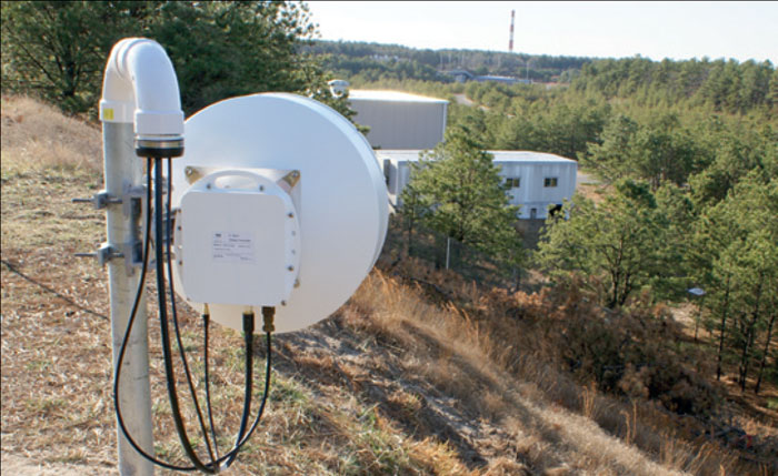
Image credit: BNL.
The 16 kicker cavities in the longitudinal system operate at frequencies of 6.0 GHz, 6.2 GHz, …, 9.0 GHz. To drive them, the pickup signal is split into 16 channels, corresponding to the individual cavities. Each channel goes through a band-pass filter with a width of 100 MHz centred at its cavity frequency so that a given cavity is driven by a sinusoidal signal whose phase and amplitude change from one bunch to the next. The individual signals are put through analogue linear modulators that adjust the phase and amplitude to obtain optimal cooling. The amplifiers are located in the tunnel close to the kickers and have a peak power of 40 W.
To set up the system, open-loop beam transfer-functions are measured at each cavity frequency. The phase and amplitude are optimized using the signal suppression observed in the pickup spectrum. Signal suppression occurs because the observed signal from the beam is the sum of the Schottky signal and the coherent beam response of the cooling system. When things are tuned correctly the observed signal has 1/4 the power of the signal without cooling. During operation the full aperture of the kicker is only 2 cm, so the cavities are open during injection and acceleration and close only after storage energy is reached.
The vertical and horizontal stochastic cooling systems employ fibre-optic links between the pickups and the kickers, with a net delay of about 2/3 of a turn. The use of fibres, with their reduced signal velocities, is possible because these transverse systems can tolerate the extra delay without compromising performance. Here the Blue cavities operate at frequencies of 4.7 GHz, 4.9 GHz, … 7.7 GHz, the Yellow cavities at 4.8 GHz, 5.0 GHz, …, 7.8 GHz. The offset in frequency between the rings is needed to avoid ring-to-ring interference via microwaves propagating from one ring to the other through the common straight sections. The Blue low-level system employs the antisymmetrical filter with S1(t) = S0(t)–S0(t–τ) + S0(t–2τ)… –S0(t–15τ) with τ = 5.000 ns to get the peaks in the signal spectrum at the cavity frequencies. Like their longitudinal counterparts, the transverse cavities are open during injection and acceleration and close once storage energy is reached.
As the beam distribution evolves and components warm up, the optimal loop parameters change. The gain and phase of the system-transfer functions are therefore automatically optimized, approximately every 5 to 15 minutes. This is done one cavity at a time so that cooling is not compromised. The open-loop system-transfer function for each cavity is measured using a network analyser. The measured transfer function is compared with a stored reference function and the phase and amplitude of the low-level gain are adjusted to minimize the mean-square difference between the measured and stored transfer functions. The one-turn delay filters of the longitudinal systems are also corrected automatically by adjusting a piezoelectric delay module in the fibreoptic cable that supplies the delay.
The stochastic cooling system has significantly improved the integrated luminosity. During 2011 vertical and longitudinal cooling was used in both rings with gold ions, while horizontal cooling was achieved using betatron coupling. With all of the other parameters held constant, the cooling system doubled the integrated luminosity per store. After the installation of horizontal cooling systems, RHIC ran with uranium–uranium collisions in 2012. Figure 2 shows collision rates in the STAR and PHENIX detectors. The cooling reduced the beam size to such an extent that the collision rates were increased by almost a factor of 3 and, when compared with no cooling, the integrated luminosity was increased by a factor of 5.