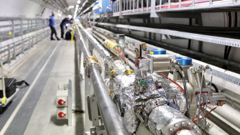
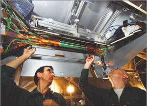
The silicon pixel detector in ALICE has an important role to play in demanding conditions at the LHC
The ALICE experiment at the LHC is optimized for the study of heavy-ion collisions to investigate the behaviour of strongly interacting matter under extreme conditions of compression and heat. The interpretation of the data will rely on a systematic comparison of measurements with the same observables in proton–proton (pp) and proton–nucleus (pA) collisions, as well as in collisions of lighter ions under the same experimental conditions. The tracking and particle-identification capabilities of ALICE are designed to allow a precise study of these benchmarking processes and to perform efficiently in the particularly demanding conditions of the heavy-ion programme.
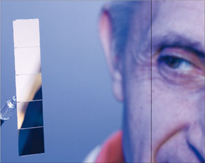
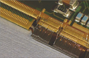
Image credit: Antonio Saba for CERN.
A key characteristic of heavy-ion collisions at the LHC energy is the high number of particles produced per event, more than two orders of magnitude higher than in a typical proton–proton collision in the central region. The design of ALICE is optimized for a charged particle multiplicity of around 4000 and has been tested with simulations up to double this number. The use of mainly 3D hit information with many points (up to 150) in a moderate magnetic field of 0.5 T makes the tracking capability particularly safe and robust.
Tracking in the central barrel of ALICE is divided into a six-layer silicon-vertex detector, which forms the inner tracking system (ITS) surrounding the beam pipe, and the time-projection chamber (TPC). The main functions of the ITS are the localization of the primary vertex (with a resolution better than 100 μm), the reconstruction of the secondary vertices from the decays of D and B mesons and hyperons, the tracking and identification of particles with momentum below 200 MeV/c, and improving the momentum and angle resolution for particles reconstructed by the TPC. The silicon pixel detector (SPD) forms the innermost two layers of the ITS, which is surrounded by two layers of drift detectors and two layers of double-sided microstrips. The drift and microstrip layers are equipped with analogue readout for independent particle identification via energy loss, dE/dx, in the non-relativistic region, thus providing the ITS with stand-alone capability as a spectrometer for particles with low transverse momentum, pt.
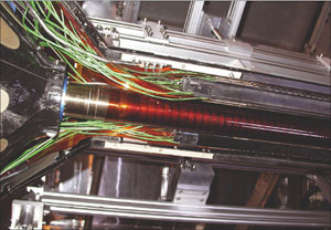
The SPD will operate in a region where the track density could be as high as 50 tracks/cm2. It has a key role in the determination of the position of the primary vertex and in the measurement of the impact parameter of secondary tracks originating from the weak decays of strange, charm and beauty particles. The active length of the two SPD layers is about 28 cm, with an acceptance coverage in pseudorapidity of η = ±2.0 for the inner layer and η = ±1.4 for the outer one, located around the beam pipe at average distances of 39 mm and 76 mm from the beam axis, respectively. The smallest clearance between the inner layer and the wall of the beam pipe – an 800 μm thick beryllium cylinder with an outer diameter of 59.6 mm – is less than 5 mm.
A distinctive feature of the SPD is the reduced amount of material seen by traversing particles. The resolutions in momentum and impact parameter for low-momentum particles are dominated by multiple scattering in the material of the detector. To keep the pt cutoff as low as possible, the SPD design uses several specific solutions to minimize the amount of material in the active volume. The result is that a straight track perpendicular to the detector surface traverses on average an amount of material per layer corresponding to about only 1% of a radiation length.
Another important consideration is the amount of radiation to which the SPD will be exposed during LHC operation. For 10 years of a standard running scenario, the integrated radiation levels of total dose and fluence on the inner layer are estimated to be 2.7 kGy and 3×10¹² n/cm2. (1 MeV neutron equivalent), respectively. While this is lower than for other LHC detectors, the on-detector ASICs for the SPD have nevertheless been implemented in radiation-hard, deep-submicron technology, like the other more demanding cases at the LHC. The relatively modest radiation levels allow the detector to operate at ambient temperature without the risk of significant long-term degradation of the sensor characteristics. The total power dissipation in the on-detector electronics is around 1.35 kW. This is not high; however, because the mass of the detector is low, if the cooling system were to fail, the temperature would rise at a rate of about 1 °C/s. For this reason, the SPD has fast-acting, redundant temperature safety systems.
The basic components of the SPD are hybrid silicon pixels in the form of a two-dimensional matrix of reverse-biased silicon detector diodes. Each diode is connected through a conductive solder bump to a contact on a readout chip that corresponds to the input of a readout cell. The readout is binary: for each cell, a threshold applied to the pre-amplified and shaped signal produces a change in the digital output level when the signal is above a set threshold.
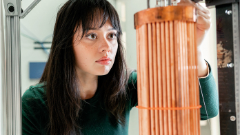
The SPD contains 1200 readout pixel chips and a total of 107 cells. The detector element is called a ladder, which consists of a silicon-sensor matrix bump-bonded to five readout pixel chips. The ladder sensor matrix contains 256×160 cells measuring 50 μm (rφ) by 425 μm (z), with longer sensor cells in the boundary region to assure coverage between readout chips. The ladders are attached in pairs to an interconnect (the pixel bus) that carries data/control bus lines and power/ground planes; a multi-chip module (MCM), located at one end of the pixel bus, controls the front-end electronics and is connected to the off-detector readout system via optical-fibre links.
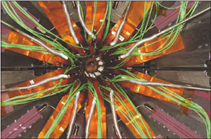
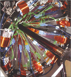
Two ladders, the pixel bus and the MCM together form the basic detector module, known as a “half stave”. Two half staves, attached head-to-head along the z direction to a carbon-fibre support sector, with the MCMs at the two ends, form a stave. Each sector of the SPD supports six staves; two on the inner layer and four on the outer layer, and ten sectors mounted together in enclosed geometry around the beam pipe form the full two-layer barrel. Each half stave generates an 800 Mb/s output serial-data stream. The 120 half staves that form the SPD are all read in parallel, with full detector readout taking around 256 μs.
Although small in physical size, the SPD is packed with advanced and novel technical solutions, including the following few examples. To obtain the lowest material budget, the pixel ASIC wafers were thinned down to 150 μm after deposition of the solder bumps, which are about 20 μm in diameter. They were then diced and the die flip-chip bonded to 200 μm thick silicon sensors to form a ladder. This whole process was challenging and required specific developments by the industrial partners (VTT in Finland, Canberra in Belgium and ITC-irst, now FBK, in Italy).
Material budget considerations also led to the development of the pixel bus, a high-density aluminium/polyimide multi-layer flex. This technology, in which aluminium is used in place of copper, is not an industry standard and was made possible by the expertise available in the TS-DEM workshop at CERN. The optical transceiver module (one on each MCM), housed in a silicon package barely 2 mm thick, is a custom development by the same company that produced the optical links for the two larger LHC detectors.
The cooling system is of the evaporative type based on C4F10 and has required a specific system development. The sectors are equipped with cooling tubes and capillaries embedded in the carbon-fibre support sector, running underneath the staves (one per stave). The cooling tubes are made from a corrosion-free metal alloy (Phynox) with walls only 40 μm thick.
A unique feature of the SPD is its capability to generate a prompt trigger based on an internal Fast-OR. Each pixel chip provides a Fast-OR digital pulse when one or more of the pixels in the matrix are hit. This was originally included for self-test purposes, but it became clear that it could be adapted to generate a multiplicity trigger with a considerable interest for physics.

The Fast-OR signals of the 10 chips on each of the 120 half staves are transmitted every 100 ns on the 120 optical links that are also used for the data readout. They are processed in a separate processor unit according to a variety of predefined trigger algorithms to generate a signal that can contribute to the Level 0 (L0) trigger decision in the ALICE central trigger processor (CTP). Simulations have shown that using the Fast-OR information in the L0-trigger decision significantly improves background rejection in proton–proton interactions and event selection in heavy-ions runs.
The pixel-trigger signal generated by the Fast-OR processor must reach the CTP within about 800 ns of the interaction to meet the latency requirements of the L0-trigger electronics. The design has brilliantly met this challenging requirement for the trigger processor in tests and the full system is now being commissioned in ALICE with cosmic rays.
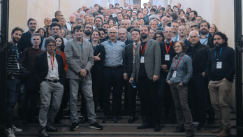
A major challenge for the LHC collaborations has been to bring together components and subsystems developed at institutes and production laboratories in different countries and locations. The SPD is no exception. The laboratories that took part in the design, development and construction of the SPD are: CERN, INFN and the University and Politecnico of Bari, INFN and the University of Catania, INFN/Laboratori Nazionali di Legnaro, INFN and the University of Padova, INFN and the University of Salerno, INFN and the University of Udine, and the Slovak Academy of Sciences of Košice.
The final integration of the SPD took place at CERN’s Departmental Silicon Facility, which was equipped to test the individual sectors and for the integration and pre-commissioning of the full detector, including the cooling plant and the full-scale configuration of power supplies and services. This strategy proved invaluable for debugging the system before installation in the experimental area.
In June 2007 the SPD was finally installed in the ALICE experimental area at Point 2 in the LHC ring, with connection to services possible in November, when the mini-frame carrying service interfaces was put in place.
Commissioning of the SPD started in January 2008 with the aim of being fully ready by the time that the LHC delivers the first proton–proton collisions, scheduled for later this summer. Indeed, the SPD is one of the ALICE sub-detectors to contribute to the measurement of the charged-particle multiplicity, which is the common objective of “day-one” studies for all of the LHC experiments.
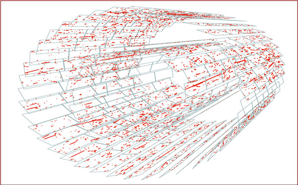
Since May the SPD has been collecting cosmic data triggered by the Fast-OR trigger signal produced by the SPD itself. The events are selected by requiring at least one hit in the outer layer of the top half-barrel in coincidence with at least one hit in the outer layer of the bottom half-barrel. These data samples are being used for a preliminary alignment of the SPD components. More recently the same signal is being used to trigger other ALICE subdetectors: first the other two ITS systems – the drift and double-sided microstrip detectors – and then the TPC, thus exercising the combined TPC-plus-ITS tracking.
On the evening of 15 June, while preparing the detector for the cosmic run, the triggered events from the SPD showed a puzzling pattern never seen before. It took a while for the team working in the control room to realize that the SPD was observing one of the first signs of life of the LHC at Point 2: muon tracks produced in the beam dump during the injection test in transfer line TI 2.
• It is unfortunately impossible in this short article to give the well deserved credit to all of those who have deployed a relentless effort over nearly a decade to lead to completion this complex and exciting detector successfully to completion.