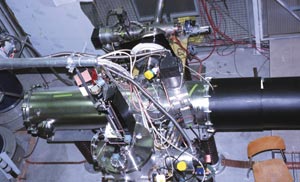
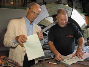
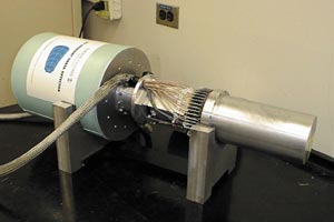
On 22 August the last of three Russian trucks left CERN for Moscow carrying, as a long-term loan, a laser ion source in 93 boxes with a total volume of 150 m3 and a weight of 42 tonnes. This marked the end of more than 10 years of R&D work on a high current, high charge state, heavy ion source that has the potential to provide beam for the Large Hadron Collider (LHC) and other heavy ion accelerators demanding extremely high beam intensities, such as the Terawatt Accumulator, TWAC, at Moscow. At the same time, the journey marked the beginning of a new phase in the life of the laser ion source (LIS).
Only three different types of source are thought able to reach the performance needed for high-intensity heavy ion machines: the electron-beam ion source (EBIS); the LIS, which has been studied in close collaboration between CERN and Russia; and the electron cyclotron resonance ion source (ECRIS), which is used in combination with an accumulator ring to fatten the beam.
In the LIS developed at CERN, intense laser radiation heats the target surface causing the emission of atoms and a plasma containing low charge-state ions. This plasma is then heated by the laser radiation, such that the ions are ionized 20-30 times. These ions are then extracted by an electrostatic field before acceleration by a radio-frequency quadrupole (RFQ).
For many years studies were done with a commercially available CO2 laser providing a 30 J pulse every 30 seconds, but its energy, pulse form and pulse repetition rate were far from the parameters required to produce an ion beam for LHC. The present Heavy Ion Linac at CERN, LINAC3, feeding the PS Booster in single-turn injection, would need a 5 µs long pulse with some 1010 lead ions in charge state 25+, every second. For this reason the two Russian institutes in the collaboration, ITEP and TRINITI, designed and built a CO2 laser capable of delivering 100 J pulses in 27 ns with a 1 Hz repetition rate. The project was co-funded by the European Union and CERN.
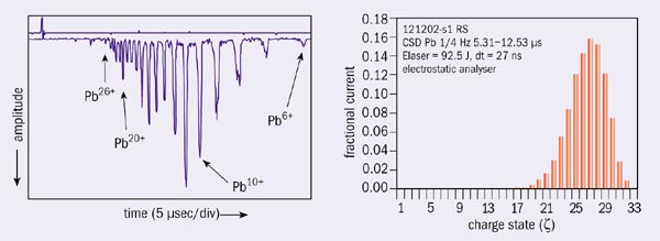
With the new laser, power densities of 1013 W/cm2 were obtained on the target of the ion source. For 1 Hz pulse trains lasting more than 60-70 minutes, statistical fluctuations in pulse amplitude and pulse width from shot to shot were less than ±15%.
The two measured charge-state distributions of ions shown in the figure demonstrate the progress over the past 10 years. The second distribution was obtained in December 2002, shortly before the source was shut down. Extrapolating current densities from the measuring point (an electrostatic analyser) to real extraction geometries leads to 1-2 x 10¹⁰ Pb27+ in a pulse of 3-4 µs. The fact that with an RFQ and an interdigital-H-type (IH) RF structure, as used in LINAC3, three different charge states can be accelerated simultaneously up to the first stripper, gives confidence that LHC conditions can be fulfilled comfortably. Nevertheless, converting the laser prototype to a device satisfying LHC reliability standards, interfacing this source to LINAC3, and accelerating the ions to the energy needed at the entrance of the IH structure, meant further R&D. CERN, at present under pressure to reduce R&D work for the sake of LHC progress, decided to use LINAC3 (with an ECRIS) and LEIR, the former Low Energy Antiproton Ring, as the first heavy ion source. This freed the LIS for an immediate application at TWAC.
With the new CERN/ITEP Collaboration Agreement, the LIS will be used not only to produce medium-mass ions as required by TWAC for its daily operation, but also for R&D on source performance, which will continue in parallel. Le roi est mort, vive le roi!
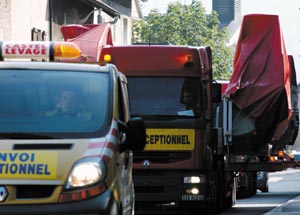
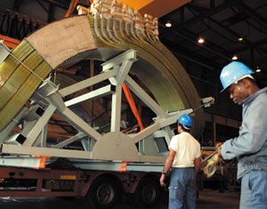
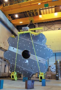
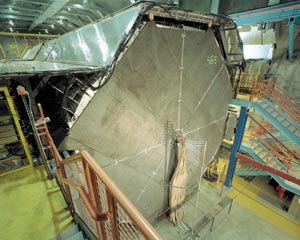
On 25 September the two large coils for the ALICE dipole magnet arrived at Point 2 of the Large Hadron Collider (LHC) after a 1200 km journey from their manufacturer. The two coils, which are 5 m long, 6 m wide, more than 3 m high, and weigh 20 tonnes each, were manufactured by Sigmaphi in Vannes, France. They will form the dipole magnet of the forward muon arm spectrometer of the ALICE detector.
Even loading the huge coils at Sigmaphi was not a simple task. The overhead crane could not be used to lift the coils plus their supports, so the coils had to be jacked up on rollers and pulled outside the hall, where a mobile crane lifted them onto the trucks. Moreover, the big door of the assembly hall was too small and part of the wall had to be cut open to roll out the coils. Once on the road, detours were necessary because of the height of bridges and so on.
The two coils will be installed within a 780 tonne iron yoke, which has been manufactured in Russia and is on its way to CERN. The dipole magnet will be used to identify high-momentum muon pairs and will be one of the biggest dipoles operating at room temperature. The impressive size and gap width between the poles of 3-4 m is necessary to obtain the required acceptance angle of 9°. The electrical power dissipation will be close to 4 MW, and to reach the nominal field of 0.7 T, it will be powered by a DC power converter providing 6000 A.
In April 2007, one of the largest and most complex sets of scientific instruments ever constructed – the Large Hadron Collider (LHC) and its four companion detectors – is scheduled to begin its odyssey into the uncharted waters beyond the Standard Model of particle physics. The discoveries that are likely to be made there could fundamentally change our ideas about the basic constituents of matter, and therefore our concepts of the universe itself. It is this hope that has led the 20 member states of CERN, and a number of non-member state partners as well, to promote, develop, fund and build the LHC project. In addition, several thousand physicists have bet a substantial part of their careers on the success of the LHC.
From the initial concept in the mid-1980s, the LHC project has followed a winding road on its way to completion. Challenging the frontiers of technology on many fronts simultaneously is one of its biggest risks, as in many cases the appropriate solutions to technological issues – and their costs – had to be presumed well in advance of construction. The sheer size of the LHC itself, and of the two biggest detectors ATLAS and CMS, presented major challenges in civil and mechanical engineering, as physicists and engineers struggled to optimize the physics return for minimal size and cost. The project has also written new standards for international co-operation in science, as much of the apparatus is being constructed in laboratories all over the world and then brought to CERN for final assembly. These tasks have often been accomplished by international teams of technicians working across a variety of languages and cultures, but with a common goal in mind. For the most part this process has worked very well indeed, and at the time of writing the ATLAS collaboration consists of about 1700 physicists from more than 150 institutions.
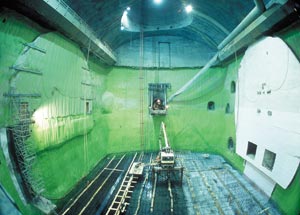
A significant milestone was achieved on 4 June this year when the ATLAS detector cavern, UX15, and its associated buildings and underground structures at Point 1 on the LHC ring were accepted on schedule by CERN. The day was marked by a ceremony and commemorated by many dignitaries, including Pascal Couchepin, president of the Swiss Confederation, Carlo Lamprecht, Geneva state councillor, and CERN’s director-general Luciano Maiani. With this dedication, Winston Churchill’s famous phrase from a very different era comes to mind: “We have reached the end of the beginning” of ATLAS construction. Now the difficult work of assembling ATLAS underground can start.
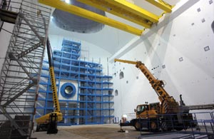
The words “ATLAS installation” do not nearly do justice to the magnitude of this task. During a three and a half year period from April 2003 until December 2006, more than 7000 tonnes of large, delicate apparatus will be lowered into UX15, itself located 100 m underground. The many heavy objects must be aligned with very high precision so ATLAS is able to measure particle trajectories and energies with the accuracy required to extract the fundamental secrets of nature for which it is searching. Then, from the end of December 2006 until the beam is turned on in April 2007, the early commissioning of ATLAS will occur. When ATLAS is “ready for physics”, more than 100 million sensors will be alive inside the detector. It will produce petabytes of information per year when the LHC achieves full luminosity.
ATLAS will be the largest-volume detector ever constructed for high-energy physics at 46 m long, 25 m wide and 25 m high. However, at 7000 metric tonnes it is not the heaviest detector – that honour belongs to another of the LHC detectors, CMS, which weighs 12,500 metric tonnes. The relatively light weight of ATLAS is due to the design of its superconducting magnet system, which is based on air-core barrel and endcap toroid magnets and a central solenoid that will provide a field of 2 Tesla.
Not surprisingly, costs have played a major role in determining the final design and configuration of ATLAS. In particular, cost considerations limited the size both of the ATLAS experimental hall and its access shafts, and the detector was in turn designed to make optimal use of the available space – but with sufficient modularity that individual pieces would fit within access-shaft allowances. It was determined early on that two smaller access shafts were significantly cheaper than one shaft large enough to accommodate the entire detector or a major sub-assembly. In another cost-cutting move, the dimensions of the barrel toroid coils were minimized, as were the access shafts. However, the final design for the ATLAS cavern UX15 is not much different in size from the original concept: its dimensions are an enormous 53 m long, 30 m wide and 35 m high.
Given the large volume of UX15, there were important geologic considerations to take into account in determining its location on the LHC ring. Of the available sites, Point 7 was best in terms of stability and absence of water leakage, but ruled out due to the proximity of civil constructions in neighbouring Ferney-Voltaire. Of the remaining locations, Point 5 was ruled out because the rock formations there are not robust enough to support a cavern the size of UX15. In the end, Point 1 was chosen as the least expensive alternative – other sites would have required costly remediation. But there are issues even at Point 1; since ATLAS is light compared with the rock formerly in place, there is expected to be significant upward floor movement that must be estimated and taken into account in the ATLAS installation.
The ATLAS civil construction was also interesting from another point of view – the desire to execute as much of it as possible without interfering with the operations and infrastructure of LEP. To do this the UX15 cavern was built “from the top down” using a novel suspended roof that was later “lowered” into place when the cavern walls were completed. This ingenious solution to a complex problem is typical of the outstanding creativity of CERN’s Civil Engineering Group and its consultants in their approach to the construction of the LHC project.
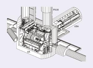
Another cost-saving measure was the decision to minimize strictly the construction of new buildings for the pre-assembly of major components of ATLAS above ground. Because there is no staging area, some of the large subcomponents of ATLAS – for example the barrel toroid magnet – will be completely assembled for the first time only when underground in UX15. As much pre-assembly and testing as possible will be done on the surface, but there is a limit to how much can be done. And since there is no large staging space available at Point 1, detector components, having been assembled at various locations at CERN, must be transported to Point 1 for installation. As some of these items are enormous, this is a task requiring great care. All this implies the need for a very carefully sequenced and choreographed installation procedure. For all these reasons ATLAS is sometimes referred to as a modern day “ship in a bottle”.
These considerations also determine the installation strategy to be used. The installation process is organized into six sequential phases: (1) surface and underground infrastructure, (2) barrel toroid and barrel calorimeters, (3) barrel muon chambers and endcap calorimeters, (4) inner detectors and muon “big wheels”, (5) endcap toroids and muon “small wheels” and (6) vacuum pipe, shielding and closing. Of course, considerable testing will be done en route to ensure that components are working properly and once installation is complete it will be extremely difficult, almost impossible, to work backward to remove any of the large sub-detectors for major servicing. The barrel toroid is perhaps the most dramatic case in point.
Safety is a paramount concern for everyone in ATLAS, and all the installation activities have been designed with this in mind. Elaborate but practical procedures control the access of people into Point 1, especially the underground areas. Entry of tools and materials will also be carefully monitored so that, for example, when the large magnets are finally energized there will be no metal flying about. The future presence of large amounts of liquid argon in UX15 is also an important safety concern.
The ATLAS Technical Coordination Team has organized the installation strategy using modern project-management ideas and tools. Resource needs (people, cash, special tools, cranes, etc) and schedules are evaluated and monitored using resource-loaded scheduling based on work package, deliverable and milestone concepts. The installation schedule is very much viewed as a living document. It currently contains over 1800 individually scheduled tasks.
The installation of each of these enormous detectors is a rewarding but formidable challenge. Stay tuned to CERN Courier for the latest updates!
An important milestone has been passed in the manufacture of the magnets for CERN’s Large Hadron Collider (LHC). By the end of August 2003, 154 dipole coils – representing a whole octant of the LHC – had been produced, “collared” and approved. This shows that large-scale production of the dipoles is now under way.
The manufacture of the coils, which contain the superconducting cable to provide the all-important 8.33 T magnetic field for the LHC, represents 60% of the magnet production work. The niobium-titanium coils create the magnetic fields to guide the two counter-rotating proton beams in separate magnetic channels, but within the same physical structure. The coils are surrounded by non-magnetic “collars” of austenitic steel, a material that combines the required properties of good thermal contraction and magnetic permeability. The collars hold the coils in place against the strong magnetic forces that arise when the coils are at full field – the force loading 1 m of dipole is about 400 tonnes.
In the next stage of the process, each collared coil is installed in a magnetic yoke and a cryogenic vessel, ready for cooling to 1.9 K. This overall assembly is known as the “cold mass”. The cold masses are then transported to CERN, inserted into their blue cylindrical cryostats, and tested. By the end of 2003 a whole octant of completed cold masses should have arrived at CERN.
The task of building the coils and assembling them into cold masses has been assigned to three firms or consortia – Alstom-Jeumont (France), Ansaldo (Italy) and Noell (Germany). Each of these three suppliers received an order for 30 pre-series magnets and a subsequent one for 386 series magnets. With the pre-series phase coming to an end – 85 cold masses have already been delivered to CERN – the three firms are now embarking on large-scale series production. To meet the schedule, each firm will have to produce three cold masses a week from the end of spring 2004 onwards.
For cold-mass assembly the firms will have to overcome two major difficulties: preserving the magnet geometry and welding the so-called shrinking cylinders, which contain the cold mass. The first challenge stems from the fact that the magnets must be slightly curved to follow the circular path of the LHC ring. Over the total 15 m length of each magnet, the sagitta (difference from a straight line between the ends and the centre) must be 9 mm, to a precision of just 1 mm. The welding of the two half-cylinders that make up a shrinking cylinder relies on a special technique developed at CERN and transferred to industry. To ensure that production is properly monitored and to help the three firms step up their production rates, 15 engineers and technicians from CERN are spending 50% of their work time at the premises of the three suppliers.
Using the full length of the linear accelerator, as well as loops and bends in the beam, and the usually troublesome effect of the wakefield, SLAC has made the world’s shortest bunches of electrons – 12 µm in length and 80 fs in time. During its first run in May, the Sub-Picosecond Pulse Source (SPPS) made high-current, ultra-short bunches of electrons and turned them into very-bright, ultra-short pulses of X-ray light. These first X-rays made by a linear accelerator are in pulses 1000 times shorter than those made by storage rings such as SPEAR at Stanford in the US, enabling direct observations of atomic motion in matter that has never been seen before.
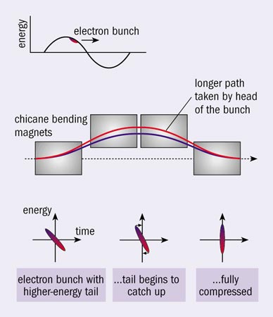
SPPS relies on several tricks to compress the bunches, which contain 2.1 x 10¹⁰ electrons, to reach a peak current of 30 kA. The gymnastics occur in three stages, starting as the bunches leave the damping rings near the beginning of the linac. At this point a bunch travels around the curve of the ring-to-linac (RTL) beamline and is compressed from 6 mm down to 1.2 mm. In the RTL, the bunch looks like a surfer climbing a wave – the front of the bunch has more energy (i.e. it is closer to the top of the radiofrequency wave) than the back. Going through the curved path of the bending magnets, the low-energy tail takes the shortest path and catches up to the head, making the bunch shorter.
The second step in bunch compression takes place at Sector 10, one-third of the way down the linac, where the electrons have been accelerated to 9 GeV. At this point the bunches are tipped to ride slightly ahead of the wave crest, so the rear is accelerated more than the front. Entering a chicane with four bends, the higher-energy tail is able to take the shortest path and catch up again, compressing the bunch to 50 µm.
The final step in compressing the bunch is something that can only be done at SLAC. It involves picking up energy along the remaining two-thirds of the linac and using an effect previously considered a nuisance. As the electron bunches travel at the speed of light, they generate an electric wake, which is known as a wakefield. In free space the wake would spread out perpendicular to the direction of travel of the electrons, but in the beam pipe the wake made by the head of the bunch bounces off the pipe and interferes with the tail. Thus the tail has less energy than the head when a bunch reaches the end of the linac.
Fortuitously, at SLAC the bunch can be routed through the Final Focus Test Beam, where the beamline jogs right then left. This geometry forces the higher-energy front to take a longer path, and the rear catches up again. Here, the bunch has rotated upright again and is now 12 µm long. At this length the bunch of 2.1 x 10¹⁰ electrons passes a fixed point in only 80 fs. After compression the bunches are wiggled by an undulator magnet, which is on loan from Argonne National Laboratory in the US, to generate the X-rays.
The SPPS will operate over the next two years, taking data in anticipation of the Linac Coherent Light Source that will make even brighter X-rays.
Germanium crystals have long been used to study photons with energies from 50 keV to 10 MeV. Their excellent energy resolution (approaching 0.1%) has created numerous applications in nuclear and particle physics, especially in studies of nuclear structure. Their major limitations are their poor position resolution and inability to reconstruct multiple interactions. Now, germanium crystals are being made to do “double duty”, measuring the interaction points as well as the deposited energy, which allows for full 3D reconstruction of the energy deposition.
Photons with energies of less than a few million electronvolts interact primarily by Compton scattering. They usually interact several times before stopping, and many photons escape from conventional detector arrays without depositing their full energy. These partially reconstructed events constitute a substantial background to measurements. To reduce this background, existing germanium detectors are usually surrounded by thick anticoincidence (veto) counters. This veto greatly reduces the efficiency of large detector arrays.
The new breakthrough is to make germanium crystals work like miniature time-projection chambers, with the charge deposition measured at each point in the crystal. A central cathode embedded in the crystal generates a radial electric field. Electrons liberated by photon interactions in the crystals drift to segmented anodes that cover the crystal surface. Charge sharing between adjacent electrodes allows position resolutions of 1-2 mm, far better than the current one-crystal (5-10 cm) resolution. The electron drift time is also measured, which gives the depth of the interaction in the crystal and provides 3D space points. With good segmentation, complex interactions can be reconstructed, which greatly increases the photon detection efficiency while maintaining optimum resolution.
In many experiments to study very unstable nuclei, excited nuclei are produced at high velocities. To obtain gamma-ray spectra from these nuclei it is necessary to correct the photon energies for the nuclear Doppler shift; the accuracy of this correction depends on the precision of the photon position measurement. Another important application is precision nuclear spectroscopy, where the increased efficiency is needed to study multistep decays. For example, highly spinning nuclei may emit 20 or more photons as they de-excite. The ability to detect many photons in a single event greatly increases the experimental sensitivity to these reactions; high efficiency is critical for obtaining the required high-coincidence spectra.
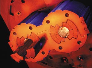
Two large collaborations are developing gamma-ray tracking arrays using segmented crystals with appropriate read-out. In the US, the Lawrence Berkeley National Laboratory-led GRETA/GRETINA collaboration is building a segmented triple-crystal prototype module. Each crystal is covered with 36 electrodes (see figure). The read-out electrodes are segmented longitudinally and transversely. Each channel is instrumented with a low-noise pre-amplifier and a fast (100 Megasamples per second), accurate (14 bit) analogue-to-digital converter. The energy resolution is 1.9 keV for 1.33 MeV gamma rays, which is comparable to the best unsegmented detectors. GRETINA will be composed of 10 triple-crystal modules covering about 25% of 4π. It will travel from accelerator to accelerator, following the best physics. The follow-on to GRETINA, the 120-crystal GRETA detector, will have full 4π coverage.
The proposed 180-crystal (6500 channels) European AGATA array, also for nuclear spectroscopy, uses a similar technology to GRETINA. These arrays will have figures of merit that are several orders of magnitude better than existing large arrays, such as Gammasphere at Argonne and Eurogam at IReS in Strasbourg.
A few smaller arrays are already operational. At the Michigan State University cyclotron in the US, the SeGA array comprises 18 crystals, each with 32-segment read-out. These crystals are slightly smaller, with a 5 keV energy resolution. The EXOGAM array at GANIL in Caen, France, has 64 crystals, each with four segments, to measure the depth of interaction. Similarly, Miniball at CERN has 40 crystals with six segments. The proposed Canadian TIGRESS array at TRIUMF will comprise 64 eight-segment crystals.
Even for simple events, the improved position resolution is an important development. The resolution could lead to better images from positron emission tomography cameras, where two reconstructed 511 keV photons are used to localize positron annihilation in patients for various medical and biological applications.
The technique may also be used to reduce backgrounds in double beta decay and dark matter searches. The US Majorana collaboration proposes to build a 200-crystal germanium detector containing 500 kg of 86% enriched 76Ge to study these topics. Simulations indicate that the position resolution obtainable with segmentation can lead to a factor of 5 to 8 rejection in backgrounds.
On 14 August, after four years of mining, construction and testing, the Main Injector Neutrino Oscillation Search (MINOS) collaboration announced the start-up of its 5400 tonne neutrino detector in the Soudan Underground Laboratory in Minnesota, US. The completion of the “far” detector, located 700 m underground, came nine months ahead of schedule. The installation of a smaller “near” detector at the US Fermi National Accelerator Laboratory will begin next spring and completion is expected in August 2004. Using a new muon-neutrino beamline, currently under construction at Fermilab, the MINOS experiment will measure the energy dependence of the neutrino oscillation probability and provide precision measurements of neutrino oscillation parameters.
The 30 m long MINOS far detector comprises 486 massive planes, lined up like the slices of a loaf of bread. Each plane consists of an octagonal sheet of steel about 8 m high and 2.5 cm thick, covered on one side with a layer of scintillating plastic. With a total of 28 000 m2, the far detector features the largest scintillator area of any particle physics detector in the world. A number of university and laboratory groups in the US and UK were involved in the mass production of the scintillator detector components, while the assembly of scintillator modules took place at the University of Minnesota, the California Institute of Technology and Argonne National Laboratory in the US.
Over the past three years the MINOS collaboration has conducted a series of calibration measurements with the CERN Proton Synchrotron proton beam. Led by a team from the UK, the collaboration has examined the response of a 1 x 1 x 3 m mini-version of the MINOS detectors to pions, muons and other particles with energies from 0.5 to 10 GeV. The calibration of the electronics of the near detector will take place at CERN this autumn. The first half of the MINOS far detector has been in operation since July 2002, and the MINOS collaboration was able to present its first 12 atmospheric neutrino events at a conference in April 2003.
MINOS is the first large-scale underground neutrino experiment equipped with a magnetic coil. The 1.5 T magnetic field inside the detector allows muons and antimuons to be separated, hence distinguishing between neutrino and antineutrino interactions. The results will provide a basis for the first test of CPT symmetry in neutrino processes.
Early in 2005, when the commissioning of the neutrino beamline at Fermilab is complete, the experiment will enter its next phase. Fermilab’s main injector will send 120 GeV protons onto a carbon target to create muon neutrinos with a median energy of about 3 GeV. The neutrinos will travel 735 km through the earth from Fermilab to Soudan. The near detector, located about 1 km from the carbon target, will verify the composition of the neutrino beam. The far detector will measure the deficit of muon-neutrinos caused by oscillations. More than 1000 billion (1012) neutrinos in the beam per year will pass through the far detector, and about 1500 of them will make a collision with an atomic nucleus inside the detector. Most collisions will produce a muon, but some will create an electron or a tau, indicating an incoming electron-neutrino or tau-neutrino. Although the MINOS detector is not capable of identifying individual tau events, the experiment can statistically determine the dominant oscillation mode.
The MINOS experiment should provide the best measurement of oscillation parameters associated with the “atmospheric mass-squared region”, for which the Super-Kamiokande and K2K experiments in Japan have obtained initial results. For the “solar mass-squared region”, Super-Kamiokande and KamLAND in Japan, and the Sudbury Neutrino Observatory in Canada have provided the relevant results. OPERA and ICARUS, two future neutrino experiments to take place in the Gran Sasso Underground Laboratories in Italy, are aimed at directly observing the appearance of tau-neutrinos from muon-neutrinos. These experiments will use the 730 km muon-neutrino beam of the CERN Neutrinos to Gran Sasso project, which is currently under construction and scheduled to start up in 2006.
More than 200 people from 32 institutions in Brazil, France, Greece, Russia, the UK and the US are involved in the MINOS project. Most of the funding for the experiment and the neutrino beamline at Fermilab has come from the US Department of Energy, which will have provided $171 million. The UK’s Particle Physics and Astronomy Research Council has contributed about $10 million, and about $4 million has come from the State of Minnesota, the University of Minnesota and the US National Science Foundation.
This summer the IT division at CERN was a hive of activity as dozens of young software engineers worked round the clock to launch the LHC (Large Hadron Collider) Computing Grid (LCG) into its first phase of operations. Meanwhile, similar hectic preparations were going on at other major computing centres around the world. The LCG project, which was launched last year, has a mission to integrate thousands of computers worldwide into a global computing resource. This technological tour de force will rely on novel Grid software, called middleware, and will also benefit from new hardware developments in the IT industry.
The challenge facing the LCG project can be summarized in terms of two large numbers. The LHC will produce more than 10 petabytes of data a year – the equivalent of a stack of CDs 20 km high – and require around 100,000 of today’s PCs to analyse that data. Behind the numbers, however, is a new philosophy. The data and processing power should be available to the thousands of scientists involved in LHC experiments in a completely seamless fashion, independent of their location. This is the philosophy of computer Grids, which take their name from the ubiquitous, highly reliable electricity grid with its plug-in-the-wall simplicity.
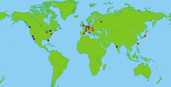
The LCG project has been rapidly gearing up for this challenge, with more than 50 computer scientists and engineers from partner centres around the world joining the effort over the past year. The first version of the LCG, called LCG-1, is now up and running on a restricted number of sites (see map) and with limited functionality. Over the next few years, however, the plan is for the LCG to grow in size and complexity, absorbing new Grid technologies and integrating many more sites.
…while the EGEE gets ready
The success of the European Union (EU)-funded European Data-Grid (EDG) project – a three-year effort led by CERN, which is due to finish in spring 2004 – has generated strong support for a follow-up project. The objective is to build a permanent European Grid infrastructure that can serve a broad spectrum of applications reliably and continuously. Providing such a service will require a much larger effort than setting up the current EDG test bed. So CERN has established a pan-European consortium called Enabling Grids for E-science in Europe (EGEE) to build and operate such a production Grid infrastructure, providing round-the-clock Grid service to scientists throughout Europe.
A proposal for such a project was submitted to the EU 6th Framework Programme in May 2003, where some €50 million has been earmarked by the commission for major Grid infrastructure projects. This proposal, again led by CERN, involves some 70 partners, encompassing all major computer centres in Europe as well as leading American and Russian centres. EGEE, following a positive evaluation by EU independent experts, has been invited to negotiate a contract with the EU for the major part of the allocated funds. Final contract negotiations with the EU are planned for November, and if all goes well the project should get under way by next spring.
The LHC Computing Grid will provide the springboard for EGEE, and in turn benefit from Grid software engineering that is part of the EGEE project. However, the mission of EGEE is also to extend the potential benefits of a Grid infrastructure beyond high-energy physics. The first target is biomedical applications, with other scientific and technological fields not far behind.
European projects galore
EDG and EGEE are by no means the only Grid projects that involve CERN. For example, DataTAG aims to provide high-speed connections between Grids in Europe and the US. In May, the project set its latest land-speed record, transferring data at nearly 1 Gbit/s (equivalent to nearly two DVD films a minute) between CERN and Chicago using the new IPv6 Internet protocol.
CrossGrid aims to extend the functionality of the EDG to advanced applications such as real-time simulations. The GRACE project is developing a decentralized search engine based on Grid technology. MammoGrid is dedicated to building a Grid for hospitals to share and analyse mammograms to improve breast-cancer treatment. GridStart aims to co-ordinate the efforts of the major Grid initiatives in Europe and disseminate information about the benefits of Grid technology to industry and society.
Ultrafast X-rays have been identified in numerous workshops and reports around the world as a key area that is ripe for new scientific investigations – with femtosecond pulses allowing the detailed study of atomic motion during physical, chemical and biological reactions. Ultrafast lasers covering most of the visible, infrared and ultraviolet regions of the spectrum already provide the capability to measure bond breaking in chemical reactions with both excellent timing resolution and very short pulses. Thus, experimenters have used lasers to tremendous advantage in thousands of investigations of time dynamics, many of which are absolutely critical to research in solid-state physics, semiconductors, photochemistry and photobiology. However, until now, ultrafast time-domain studies in the X-ray region have been almost completely lacking, even though they are needed to refine the picture of dynamics at the timescales of atomic vibration periods – about 100 fs or less, and even the possibility of resolving electron dynamics with sub-femtosecond resolution.
Through the use of synchrotron radiation, and by the novel conversion of intense laser pulses into soft and hard X-rays, scientists have recently been able to perform some innovative experiments for the first time, such as Bragg diffraction studies of phase transitions and even attosecond electron redistribution in Auger electron processes. However, the laser-based X-ray fluxes are low, the signal levels weak and the experiments are challenging to accomplish.
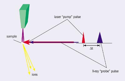
LUX – a Linac-based ultrafast X-ray/laser facility – is a concept that is designed to produce ultrashort X-ray pulses in a highly refined manner for experiments across all areas of the physical, chemical and biological sciences. The facility will provide an increase of X-ray flux by several orders of magnitude, and would be accessible to a large number of users. Ultrafast lasers would be available for “pump-probe” experiments at femtosecond resolutions, where a pulse from a laser excites or “pumps” the system under study, while the X-ray pulse is used to probe the system configuration as a snapshot in time after the pump pulse. Figure 1 shows a schematic of this concept.
While the approximately 40 available light sources in the world are largely limited to static spectroscopies, microscopies and structures, LUX will be the first to be designed from the start as a user facility for femtosecond X-ray dynamics, with precise timing as an integral requirement. It will offer high repetition rates, tunability and multiple laser sources for excitation and probe experiments, with pulses 1000 times shorter than typical third-generation light sources.
Although pump-probe experiments represent some of the most important techniques, involving a femtosecond laser as a pump and the ultrafast linac-based X-ray source as the probe, the facility will also be designed to accommodate multidimensional coherent laser spectroscopies, such as three-laser pump beams and an X-ray probe, as well as two X-ray wavelengths for double-resonance X-ray pump and probe spectroscopies. Most of these novel forms of spectroscopies with X-rays have not even been delineated yet.
The LUX proposal is based on a recirculating electron linac, which provides a compact and cost-effective configuration for the production of intense ultrafast extreme ultraviolet (EUV) and X-ray pulses, with tight synchronization to sample excitation lasers. The provision of a broad photon spectrum covering the whole range from EUV to hard X-ray wavelengths allows for both spectroscopy and diffraction studies, probing nuclear positions as well as electronic, chemical or structural properties. The design specification of a 10 kHz pulse repetition rate is matched to pump-probe experiments and allows rapid data acquisition and sample relaxation or replacement.
The facility is designed to produce ultrafast EUV and soft X-rays by a harmonic-cascade free-electron laser (FEL) technique, while hard X-rays are produced by a novel manipulation of the electron bunches followed by compression of the photon beam. The FEL process is initiated by a “seed” laser, which allows tunability of both wavelength and pulse duration from hundreds to tens of femtoseconds. Hard X-ray pulses are produced in superconducting insertion devices – undulators produce narrow-band peaks with harmonics out to 10 keV and higher, and wigglers produce broadband pulses extending to even shorter wavelengths.
The major components and systems of LUX involve existing accelerator technologies: radiofrequency (RF) photo-injector guns, superconducting linear accelerators, magnet lattices in the arcs and straight sections, transversely deflecting cavities, harmonic generation in FELs, narrow-gap short-period undulators, X-ray manipulation in optical beamlines, and a variety of short-pulse laser systems. Figure 2 shows the layout of the machine. In LUX, high-quality (low emittance, high charge) electron bunches produced in an RF photocathode are accelerated to approximately 100 MeV in an injector linac before being turned into the main linac. The main linac accelerates the electron bunches by about 700 MeV on each pass, resulting in a final energy of approximately 3 GeV after four passes. After acceleration to 3 GeV the electron bunches pass through insertion devices to produce radiation, supplied to multiple beamlines.
The beam-quality requirements of the RF photocathode gun have already been demonstrated, with a normalized emittance of approximately 3 mm mrad at 1 nC charge. The flexibility of the LUX lattice design allows the control and preservation of the transverse and longitudinal emittances of the electron beam, minimizing the influence of collective effects and allowing the manipulation of the picosecond electron bunches to produce femtosecond X-ray pulses.
To produce ultrafast hard X-rays, at the exit of the final arc the electron bunches receive a time-correlated vertical kick in a dipole-mode RF cavity – the head is kicked up and the tail is kicked down, while the centroid is unperturbed. The electrons then radiate X-rays in the downstream chain of undulators and wiggler magnets, imprinting this head-tail correlation in the geometrical distribution of the X-ray pulse. The correlated X-ray pulse is then compressed using asymmetrically cut crystal optics in order to achieve the ultrashort X-ray pulse length.
In addition, high-flux, short-pulse photons will be produced over an energy range of tens of electron volts to a thousand electron volts using a laser-seeded harmonic-cascade FEL. The high-brightness electron beam is extracted from the recirculating linac and passed through an undulator, where a co-propagating seed laser results in a modulation of the charge distribution over a short length of the bunch. This modulation enhances radiation in a following undulator at shorter wavelengths that are harmonically related to the seed. The process is repeated by modulating a fresh portion of the beam, this time with the harmonic radiation produced in the previous undulator.
Sophisticated laser systems will be an integral part of the LUX facility, providing experimental excitation pulses and stable timing signals, as well as the electron source through the photocathode laser. Each endstation will have its own dedicated laser system with optical filtering and diagnostics, all contained within a stable and controlled environment. Multiple tunable lasers covering infrared to ultraviolet wavelengths with a range of pulse durations are required for experiment initiation, together with sophisticated temporal and spatial filtering to optimize the performance for specific experimental applications.
The synchronization and timing of the ultrashort X-ray pulses with respect to the experimental excitation pulse is critical in studies of ultrafast dynamics. For LUX, the techniques of optically seeded systems and bunch manipulation prove insensitive to the usual timing jitter that arises from electron acceleration in RF systems. A laser master oscillator provides stable optical pulses, and optical distribution systems transport these pulses to each beamline, with feedback based on interferometric measurements to stabilize the path lengths. The conversion to microwave signals by photodiodes allows the generation of the RF signals for the accelerator, and for phase-locking of endstation lasers. The lasers may also be optically seeded directly from the master oscillator.
The LUX project is currently in a pre-conceptual design phase, and the facility design is being optimized in order to meet the demands of the growing number of scientific applications. Combining state-of-the-art accelerator and laser systems to produce a unique X-ray facility for the study of ultrafast dynamics presents some exciting challenges and the prospect of a bountiful future in new areas of science.
Grid computing is the computer buzzword of the decade. Not since the World Wide Web was developed at CERN more than 10 years ago has a new networking technology held so much promise for both science and society. The philosophy of the Grid is to provide vast amounts of computer power at the click of a mouse, by linking geographically distributed computers and developing “middleware” to run the computers as though they were an integrated resource. Whereas the Web gives access to distributed information, the Grid does the same for distributed processing power and storage capacity.
There are many varieties of Grid technology. In the commercial arena, Grids that harness the combined power of many workstations within a single organization are already common. But CERN’s objective is altogether more ambitious: to store petabytes of data from the Large Hadron Collider (LHC) experiments in a distributed fashion and make the data easily accessible to thousands of scientists around the world. This requires much more than just spare PC capacity – a network of major computer centres around the world must provide their resources in a seamless way.
CERN and a range of academic partners have launched several major projects in order to achieve this objective. In the European arena, CERN is leading the European DataGrid (EDG) project, which addresses the needs of several scientific communities, including high-energy particle physics. The EDG has already developed the middleware necessary to run a Grid testbed involving more than 20 sites. CERN is also leading a follow-on project funded by the European Union, EGEE (Enabling Grids for E-Science in Europe), which aims to provide a reliable Grid service to European science. Last year, the LHC Computing Grid (LCG) project was launched by CERN and partners to deploy a global Grid dedicated to LHC needs, drawing on the experience of the EDG and other international efforts. This project has started running a global Grid, called LCG-1.
Enter the openlab
The CERN openlab for DataGrid applications fits into CERN’s portfolio of Grid activities by addressing a key issue, namely the impact on the LCG of cutting-edge IT technologies that are currently emerging from industry. Peering into the technological crystal ball in this way can only be done in close collaboration with leading industrial partners. The benefits are mutual: through generous sponsorship of state-of-the-art equipment from the partners, CERN acquires early access to valuable technology that is still several years from the commodity computing market the LCG will be based on.
In return, CERN provides demanding data challenges, which push these new technologies to their limits – this is the “lab” part of the openlab. CERN also provides a neutral environment for integrating solutions from different partners, to test their interoperability. This is a vital role in an age where open standards (the “open” part of openlab) are increasingly guiding the development of the IT industry.
The CERN openlab for DataGrid applications was launched in 2001 by Manuel Delfino, then the IT Division leader at CERN. After a hiatus, during which the IT industry was rocked by the telecoms crash, the partnership took off in September 2002, when HP joined founding members Intel and Enterasys Networks, and integration of technologies from all three led to the CERN opencluster project.
IBM joins CERN openlab to tackle the petabyte challenge
The LHC will generate more than 10 petabytes of data per year, the equivalent of a stack of CD ROMs 20 km high. There is no obvious way to extend conventional data-storage technology to this scale, so new solutions must be considered. IBM was therefore keen to join the CERN openlab in April 2003, in order to establish a research collaboration aimed at creating a massive data-management system built on Grid computing, which will use innovative storage virtualization and file-management technology.
IBM has been a strong supporter of Grid computing, from its sponsorship of the first Global Grid Forum in Amsterdam in 2001 to its participation in the European DataGrid project. The company sees Grid computing as an important technological realization of the vision of “computing on demand”, and expects that as Grid computing moves from exclusive use in the scientific and technical world into commercial applications, it will indeed be the foundation for the first wave of e-business on demand.
The technology that IBM brings to the CERN openlab partnership is called Storage Tank. Conceived in IBM Research, the new technology is designed to provide scalable, high-performance and highly available management of huge amounts of data using a single file namespace, regardless of where or on what operating system the data reside. (Recently, IBM announced that the commercial version will be named IBM TotalStorage SAN File System.) IBM and CERN will work together to extend Storage Tank’s capabilities so it can manage the LHC data and provide access to it from any location worldwide.
Brian E Carpenter, IBM Systems Group, and Jai Menon, IBM Research.
At present, the CERN opencluster consists of 32 Linux-based HP rack-mounted servers, each equipped with two 1 GHz Intel Itanium 2 processors. Itanium uses 64-bit processor technology, which is anticipated to displace today’s 32-bit technology over the next few years. As part of the agreement with the CERN openlab partners, this cluster is planned to double in size during 2003, and double again in 2004, making it an extremely high-performance computing engine. In April this year, IBM joined the CERN openlab, contributing advanced storage technology that will be combined with the CERN opencluster (see “IBM joins CERN openlab to tackle the petabyte challenge” box).
For high-speed data transfer challenges, Intel has delivered 10 Gbps Ethernet Network Interface Cards (NICs), which have been installed on the HP computers, and Enterasys Networks has delivered three switches equipped to operate at 10 gigabits per second (Gbps), with additional port capacity for 1 Gbps.
Over the next few months, the CERN opencluster will be linked to the EDG testbed to see how these new technologies perform in a Grid environment. The results will be closely monitored by the LCG project to determine the potential impact of the technologies involved. Already at this stage, however, much has been learned that has implications for the LCG.
For example, thanks to the preinstalled management cards in each node of the cluster, automation has been developed to allow remote system restart and remote power control. This development confirmed the notion that – for a modest hardware investment – large clusters can be controlled with no operator present. This is highly relevant to the LCG, which will need to deploy such automation on a large scale.
Several major physics software packages have been successfully ported and tested on the 64-bit environment of the CERN opencluster, in collaboration with the groups responsible for maintaining the various packages. Benchmarking of the physics packages has begun and the first results are promising. For example, PROOF (Parallel ROOT Facility) is a version of the popular CERN-developed software ROOT for data analysis, which is being developed for interactive analysis of very large ROOT data files on a cluster of computers. The CERN opencluster has shown that the amount of data that can be handled by PROOF scales linearly with cluster size – on one cluster node it takes 325 s to analyse a certain amount of data, and only 12 s when all 32 nodes are used.
Data challenges galore
One of the major challenges of the CERN opencluster project is to take maximum advantage of the partners’ 10 Gbps technology. In April, a first series of tests was conducted between two of the nodes in the cluster, which were directly connected (via a “back-to-back” connection) through 10 Gbps Ethernet NICs. The transfer reached a data rate of 755 megabytes per second (MB/s), a record, and double the maximum rate obtained with 32-bit processors. The transfer took place over a 10 km fibre and used very big frames (16 kB) in a single stream, as well as the regular suite of Linux Kernel protocols (TCP/IP).
The best results through the Enterasys switches were obtained when aggregating the 1 Gbps bi-directional traffic involving 10 nodes in each group. The peak traffic between the switches was then measured to be 8.2 Gbps. The next stages of this data challenge will include evaluating the next version of the Intel processors.
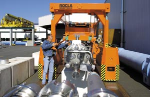
In May, CERN announced the successful completion of a major data challenge aimed at pushing the limits of data storage to tape. This involved, in a critical way, several components of the CERN opencluster. Using 45 newly installed StorageTek tape drives, capable of writing to tape at 30 MB/s, storage-to-tape rates of 1.1 GB/s were achieved for periods of several hours, with peaks of 1.2 GB/s – roughly equivalent to storing a whole movie on DVD every four seconds. The average sustained over a three-day period was of 920 MB/s. Previous best results by other research labs were typically less than 850 MB/s.
The significance of this result, and the purpose of the data challenge, was to show that CERN’s IT Division is on track to cope with the enormous data rates expected from the LHC. One experiment alone, ALICE, is expected to produce data at rates of 1.25 GB/s.
In order to simulate the LHC data acquisition procedure, an equivalent stream of artificial data was generated using 40 computer servers. These data were stored temporarily to 60 disk servers, which included the CERN opencluster servers, before being transferred to the tape servers. A key contributing factor to the success of the data challenge was a high-performance switched network from Enterasys Networks with 10 Gbps Ethernet capability, which routed the data from PC to disk and from disk to tape.
An open dialogue
While many of the benefits of the CERN openlab for the industrial partners stem from such data challenges, there is also a strong emphasis in openlab’s mission on the opportunities that this novel partnership provides for enhanced communication and cross-fertilization between CERN and the partners, and between the partners themselves. Top engineers from the partner companies collaborate closely with the CERN openlab team in CERN’s IT Division, so that the inevitable technical challenges that arise when dealing with new technologies are dealt with rapidly and efficiently. Furthermore, as part of their sponsorship, HP is funding two CERN fellows to work on the CERN opencluster. The CERN openlab team also organizes thematic workshops on specific topics of interest, bringing together leading technical experts from the partner companies, as well as public “First Tuesday” events on general technology issues related to the openlab agenda, which attract hundreds of participants from the industrial and investor communities.
A CERN openlab student programme has also been created, bringing together teams of students from different European universities to work on applications of Grid technology. And the CERN openlab is actively supporting the establishment of a Grid café for the CERN Microcosm exhibition – a Web café for the general public with a focus on Grid technologies, including a dedicated website that will link to instructive Grid demos.
Efforts are ongoing in the CERN openlab to evaluate other possible areas of technological collaboration with current or future partners. The concept is certainly proving popular, with other major IT companies expressing an interest in joining. This could occur by using complementary technologies to provide added functionality and performance to the existing opencluster. Or it could involve launching new projects that deal with other aspects of Grid technology relevant to the LCG, such as Grid security and mobile access to the Grid.
In conclusion, the CERN openlab puts a new twist on an activity – collaboration with leading IT companies – that has been going on at CERN for decades. Whereas traditionally such collaboration was bilateral and focused on “here-and-now” solutions, the CERN openlab brings a multilateral long-term perspective into play. This may be a useful prototype for future industrial partnerships in other high-tech areas, where CERN and a range of partners can spread their risks and increase their potential for success by working on long-term development projects together.
Further reading
For more information about CERN openlab, see the website at www.cern.ch/openlab.
To provide the best experiences, we use technologies like cookies to store and/or access device information. Consenting to these technologies will allow us to process data such as browsing behavior or unique IDs on this site. Not consenting or withdrawing consent, may adversely affect certain features and functions.
Functional
Always active
The technical storage or access is strictly necessary for the legitimate purpose of enabling the use of a specific service explicitly requested by the subscriber or user, or for the sole purpose of carrying out the transmission of a communication over an electronic communications network.
Preferences
The technical storage or access is necessary for the legitimate purpose of storing preferences that are not requested by the subscriber or user.
Statistics
The technical storage or access that is used exclusively for statistical purposes.The technical storage or access that is used exclusively for anonymous statistical purposes. Without a subpoena, voluntary compliance on the part of your Internet Service Provider, or additional records from a third party, information stored or retrieved for this purpose alone cannot usually be used to identify you.
Marketing
The technical storage or access is required to create user profiles to send advertising, or to track the user on a website or across several websites for similar marketing purposes.