In two world exhibitions in Geneva in 2003, a collaboration between Caltech, CERN and other international institutes set out to demonstrate the possibilities and opportunities provided by the DataTAG transatlantic high-speed “light path”, which currently allows data transmission rates up to 10 gigabits per second (Gbps). The Services Industriels de Genève extended the light path into the heart of the exhibition floor in Geneva’s exhibition centre, Palexpo, both for ITU Telecom World 2003 in October and the Information and Communication Technologies for Development (ICT4D) exhibition at the World Summit on the Information Society (WSIS) in December.
A substantial, portable data centre was built on the exhibition floor in collaboration with Telehouse, CERN’s partner in the CERN Internet Exchange Point (CIXP), which is the major centre for interchange between telecommunications operators in the Geneva area. The CIXP was extended directly to the stand in Palexpo and the DataTAG light path was able to provide 10 Gbps Ethernet connectivity from the stand to collaborators in North America – Los Angeles and Chicago in the US and Ottawa in Canada. (Ethernet has come a long way from the days when it was considered to be a technology fit only for very-local-area networks!) The equipment to operate the DataTAG link at these highest state-of-the-art speeds was provided by CISCO, Intel and HP at several points on the light path.
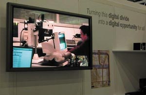
The aims of the two world exhibitions were slightly different. Telecom World 2003 continued the 20 year tradition of CERN’s involvement in demonstrations of the latest high-speed networking, and succeeded in breaking – yet again – the Internet2 records for high-speed data transmission over long distances. The ICT4D exhibition at the WSIS focused on demonstrations aimed at “turning the digital divide into a digital opportunity”, in line with the summit’s declarations.
Nonetheless, a number of items were common to both exhibitions, such as the Virtual Rooms Videoconferencing System (VRVS), which runs over the Internet; the Grid Café portal, which aims to explain and demonstrate the Grid and is proving extremely popular as a website; and the MonALISA system, which was developed by Caltech and portrays in an elegant and highly visual manner the performance of a worldwide networking system or the machines in a world Grid, and demonstrates how essential such systems are to the successful operation of Grids.
The VRVS system was fundamental to many of the demonstrations. It showed its use for international collaboration in virtual organizations, as well as in e-learning and e-lectures of several varieties, including Tokyo Lectures, a global teaching project in modern artificial intelligence in conjunction with the Swiss Education and Research Network; an impromptu presentation from the stand to the e-health conference in London; and direct sessions to the Internet2 conference in Indianapolis, including the ceremony where Harvey Newman from Caltech and Olivier Martin from CERN jointly received two Internet2 Landspeed Record awards over the Internet and announced that these records had already been broken again during Telecom World 2003.
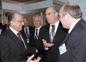
VRVS was also used when the Romanian president, Ion Iliescu, made an extended visit to the ICT4D stand at WSIS and participated in a videoconference with his compatriots back in Bucharest. President Iliescu was also able to appreciate the efforts of his compatriot Iosif Legrand, who has made the major contribution to MonALISA. E-learning and the global transmission of lectures is a strong point of such systems, especially in the context of WSIS, and plans for such exploitation are now taking off in a really meaningful manner.
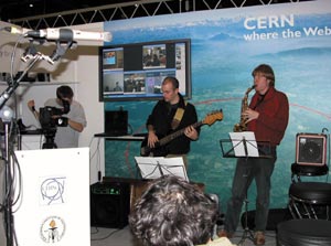
Two of the highlights on the ICT4D stand were provided by a collaboration with the Communications Research Centre in Canada. A remote “touch and feel” demonstration of haptic feedback allowed visitors to the stand in Geneva to “shake hands” with people in Ottawa and to feel the body of a dummy, as is necessary in telemedicine. This equipment is being used on a real basis in Canada for trials of remote operations. The final “bouquet” was a jazz concert, with musicians on both sides of the Atlantic playing together. Musicians from the Geneva Conservatoire de Musique played along with those from the Holy Heart of Mary Secondary School in St John’s in Newfoundland. This two-hour session demonstrated the well-developed ability of musicians to adapt to delays of a few hundred milliseconds, and the show was closed by a final jam session.
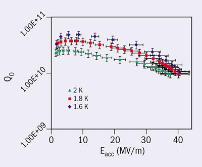
Development work for the TESLA linear collider has recently made substantial progress. After a surface treatment called electrolytic polishing, four superconducting nine-cell niobium cavities reached accelerating gradients of more than 35 MV/m. This is the performance required for an upgrade of TESLA to 800 GeV.
TESLA is the only linear collider project based on superconducting technology for particle acceleration. The first stage, with a centre-of-mass energy of 500 GeV, will require an accelerating field of 23.4 MV/m in the nine-cell 1.3 GHz superconducting niobium cavities, which are operated at a temperature of 2 K and a quality factor, Q0, of 1010. This performance has been reliably achieved at the TESLA Test Facility (TTF). In the most recent series of 24 industrially produced TTF cavities, the average gradient was 25 ± 2.6 MV/m at Q0 = 1010.
In the TTF cavities a 100-200 µm thick “damage layer” is removed from the inner surface using a chemical etching process called buffered chemical polishing (BCP). The cavities are then subjected to a 1400 °C heat treatment that doubles the thermal conductivity of the niobium at 2 K and increases the gradient by some 5 MV/m. However, after many years of intensive R&D there is now compelling evidence that the BCP process limits the attainable field in multi-cell niobium cavities to about 30 MV/m. This is significantly below the physical limit of about 45 MV/m, which is given by the condition that the radiofrequency (RF) magnetic field must stay below the critical field of the superconductor. For niobium, the maximum tolerable RF field appears to be close to the thermodynamic critical field (190 mT at 2 K).
The upgrade of TESLA to 800 GeV requires an accelerating field of 35 MV/m, which appears inaccessible with the standard cavity preparation technique by BCP. In 1997, however, scientists from KEK reported gradients of up to 40 MV/m in single-cell cavities that had been prepared by electrolytic polishing (EP) of the inner surface. The superiority of electropolishing was then confirmed by an R&D programme on single-cell niobium cavities that was carried out in a collaboration between CERN, DESY and Saclay. These successes motivated a joint KEK-DESY programme on the electropolishing of nine-cell resonators. Meanwhile, nine TTF cavities have been electropolished at the Japanese company Nomura Plating and tested at DESY.
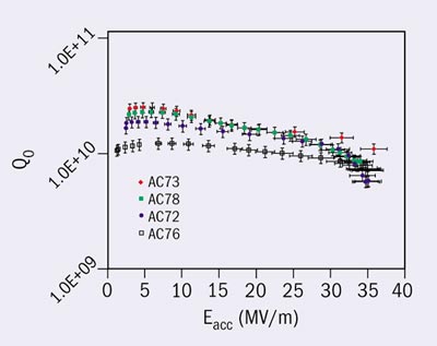
In the low-power test in a vertical superfluid helium cryostat, two of these cavities showed strong field emission at 15-17 MV/m and were therefore taken out for a second electropolishing at DESY. The excitation curves of the four best cavities are shown in figure 1. In November 2003 one of the field-emission loaded cavities was electropolished for a second time in DESY’s new EP facility. The test results of this cavity, shown in figure 2, are excellent: accelerating fields of up to 40 MV/m were reached, a record for multi-cell niobium cavities.
So far, two of the electropolished cavities have been welded into a liquid-helium tank and equipped with a high-power RF coupler, and tests with high RF power have been carried out in a horizontal cryostat at DESY. Both cavities reached the same high gradient as in the low-power test. One cavity was operated for 1100 hours at 35 MV/m and for 57 hours at 36 MV/m without any degradation. These results are clear evidence that the TESLA-800 gradient of 35 MV/m is indeed within reach.
A comprehensive understanding of why EP is so superior to BCP is still lacking, but a few explanations exist. A chemically etched niobium surface has a roughness in the order of micrometres, while an electropolished surface is an order of magnitude smoother. The sharp ridges at the grain boundaries of an etched surface may lead to local enhancements of the RF magnetic field and cause a premature breakdown of superconductivity at these localized spots. A numerical model based on this idea, developed by Jens Knobloch and colleagues at Cornell, can account for the reduction of the quality factor Q0 at high field. Magnetic field enhancements will be much smaller on the smooth electropolished surface.
Another advantage of a mirror-like surface is that a so-called Bean-Livingston surface barrier may exist, delaying the penetration of magnetic flux into the niobium, even if the lower critical field Bc1 (~160 mT for niobium at 2 K) is exceeded. An EP-treated superconducting cavity is likely to remain in the Meissner phase up to an RF magnetic field exceeding Bc1 by a significant amount, whereas a BCP-treated cavity will allow flux penetration just above Bc1, and then suffer from enhanced power dissipation caused by magnetic fluxoids entering and leaving the material.
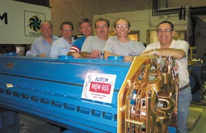
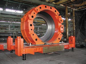
The largest piece of Canada’s $41.5 million (€32.5 million) contribution to the Large Hadron Collider (LHC) was completed in 2003 with the delivery of the last of 52 twin-aperture quadrupole magnets to CERN. These warm magnets (48 plus four spares) will be installed in the two beam-cleaning insertions of the LHC, where heating by lost beam prohibits the use of superconducting coils. The magnets, based on a CERN design, were made by ALSTOM Canada in Tracy, Quebec, with considerable input and design assistance from engineers at TRIUMF and CERN. Their small apertures (46 mm) and high gradient (35 T/m) meant that the 3.4 m long modules had to be assembled with unusually high tolerances to achieve the necessary field quality.
A prototype magnet was completed and shipped to CERN in May 1998 for mechanical and magnetic field measurements. As these measurements showed that the desired field quality had not been achieved, improvements were made in the lamination design, in the punching precision and in welding the stacks of laminations without distortion. Stronger stacking tables and a separate half-magnet assembly table were also constructed. These changes led to the first series magnet, which was completed in March 2001 and fully met the specifications. ALSTOM then proceeded to meet and eventually surpass their planned production rate of two magnets per month. Mechanical measurements were carried out at the factory to qualify the magnets prior to shipping, and detailed magnetic field measurements were made at CERN.
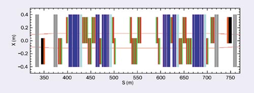
Autumn 2003 also saw the finalization of another feature of the cleaning insertions to which Canada has made a significant contribution – the arrangement of the 48 quadrupole modules and 40 collimators. In collaboration with CERN, TRIUMF has been responsible for developing a computer code to determine the optimum positions for the horizontal, vertical and skew collimator jaws, and for certain aspects of the beam optics, including matching to the arcs. An unusual feature is that as each of the focusing quadrupoles is composed of six of the magnet modules, the two beams of the LHC can be tuned independently, by wiring some modules with one beam aperture as F (focus) and the other as D (defocus), and other modules with both apertures acting in the same sense.
The decisions in 2002 to switch from copper to (much longer) graphite collimators to avoid the possibility of meltdown in an accident, and to install only half-length collimators at first, provided last-minute challenges with regard to space, impedance and collimation. Nevertheless, for the standard primary and secondary collimator apertures, which are six and seven times the rms beam width, respectively, it has been possible to find solutions that keep the collimation inefficiency below the target levels of 0.05 at injection and 0.001 at 7 TeV, with an acceptably low impedance, during phase 1, the first years of LHC physics. Moreover, sufficient space remains for the phase 2 collimators, which will support LHC operation with nominal parameters.
The remaining contributions to the LHC from TRIUMF – the major equipment for the injection kickers, the development of digital acquisition boards for the beam position monitors and beam-beam interaction studies – are also entering their final stages.
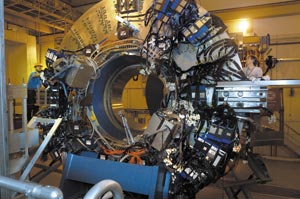
A major milestone has been reached for the STAR detector at Brookhaven’s Relativistic Heavy Ion Collider (RHIC) with the hoisting of the upper half of the endcap electromagnetic calorimeter (EEMC) into place on the “west” STAR magnet poletip. Scientists and engineers looked on with anticipation as this mammoth detector, weighing around 12.5 tonnes, was gently lowered into place, completing the mechanical installation of a key upgrade for the STAR collaboration’s spin-physics programme.
Together with the barrel electromagnetic calorimeter, the EEMC provides STAR with the capability to probe deeply into the proton’s spin structure. Specifically, the EEMC will provide forward-angle detection, identification and trigger capability for photons, electrons, positrons and electromagnetically decaying mesons. It is a key element of STAR’s plan to use polarized proton beams at centre-of-mass energies up to 500 GeV to study the gluon contribution to the proton spin and flavour-dependence (ubar vs dbar) of the sea-quark polarization.
The main thrust of the spin programme at RHIC is to add significantly to our knowledge of the spin structure of the nucleon. With the addition of electromagnetic calorimetry, STAR will provide important new information on the gluon contribution to the proton spin (ΔG(x)) by looking at the QCD Compton scattering channel, which results in a direct photon and jet. This channel is particularly “clean” in that the only other QCD subprocess that contributes is quark-antiquark annihilation, a relatively small consideration at RHIC energies. The large solid angle of STAR is ideally suited for detecting the jet and photon in coincidence, providing unique kinematic information allowing the extraction of ΔG as a function of the momentum fraction x. The EEMC is crucial to reaching the low x portion of ΔG(x) and also provides essential solid angle for the detection of high-energy electrons from parity-violating W decays, which will allow flavour-separated measurements of the polarization of the up and down antiquark sea.
A traditional lead/plastic scintillator sampling calorimeter, the EEMC is about 5 m in diameter and weighs 25 tonnes overall. It consists of 23 layers of lead (laminated with thin stainless steel for strength) between 24 layers of scintillator, resulting in 21 radiation lengths of material at normal incidence to provide a linear response for energies from 1-150 GeV.
The active area of the EEMC covers a range in pseudorapidity of 1.09 < η 2 (37.2° > θ > 15.2°). The acceptance is segmented into 720 projective towers assembled from 17 280 scintillator tiles. The signals are collected in wavelength-shifting fibres and carried via clear optical fibres (the black cables in the upper left of figure 1) to 720 photomultiplier tubes (PMTs) on the back of the magnet poletip. In addition, the detector provides fast trigger capabilities and pre- and post-shower signals valuable for electron/hadron discrimination.
Photon/π0 discrimination in the range 10-40 GeV is critical for measuring ΔG(x). Thus a shower maximum detector, consisting of two planes of triangular scintillator strips (1 cm wide) with coaxial wavelength shifting fibres, is included. The ~9000 shower maximum detector and pre- and post-shower signals are read out with 16-anode PMTs, digitized every 110 ns and stored in a digital delay line. The innovative, miniaturized read-out electronics, incorporating a 12-bit ADC for each channel, mounts directly behind a thin (9 mm) Cockroft-Walton base on each PMT. Thus 12 PMTs, bases and read-out electronics for 192 channels all reside in a compact magnetically shielded box with a single data fibre output.
The lower half of the mechanical structure and one-third of the tower energy read-out was installed and instrumented in autumn 2002. This was commissioned during the RHIC III run and provided useful tower information. The RHIC IV run began in November 2003 and the full EEMC is ready to provide energy signals and triggering. A significant block of the shower maximum and pre/post-shower detectors is also instrumented. These EEMC subsystems, as well as the barrel electromagnetic calorimeter, will be completed in the next RHIC shutdown.
The construction of the EEMC, funded primarily by the National Science Foundation, has been underway for about three years, led by a group from Indiana University with collaborators from Argonne National Laboratory, Brookhaven National Laboratory, Creighton University, the Joint Institute for Nuclear Research, Kent State University, Michigan State University, Texas A&M University and Valparaiso University.
Three months into run 4 and the PEP II accelerator, the electron-positron collider at SLAC, is performing beautifully. Recent modifications of PEP II’s hardware and operations have allowed it to maintain more intense beams, and it looks to be on course to reach the ambitious goal for run 4: 100 inverse femtobarns. If this goal is reached, the data sample from the first three runs of the BaBar detector will be almost doubled by July 2004. The detector recorded some 125 million BBbar pairs between October 1999 and July 2003, but the physicists are eager for more.
New equipment is one key to the improvements. An eighth radiofrequency (RF) cavity has been added to the accelerator, allowing more particles to be stored in the ring. Another improvement was to solve the problem of unwanted electrons in the positron ring, which are kicked loose from the beam pipe by synchrotron radiation. Their effect is to diffuse the tightly packed positron beam, thus lowering the chance of collisions with the electron beam in the detector. So technicians spent a number of gruelling weeks in a hot tunnel, winding narrow wire tape around every accessible part of the beam pipe in the positron ring. The windings created a solenoid magnet that traps the slower electrons and keeps them out of the positrons’ way. Maintenance has been another important ingredient. Over the summer, a vacuum leak in the interaction region was quickly repaired by the Mechanical Fabrication Department, and the Accelerator Maintenance RF group overhauled the entire RF system.
New ways of operating the accelerator have also started to pay off. Previously, PEP II operated with two empty buckets following each filled one. In autumn 2003 the pattern was changed: strings of buckets in which every other one is filled, alternate with shorter strings of empty buckets. Each change to the spacing between bunches affects the beams’ behaviour and the new pattern has opened up empty slots to which more particles can eventually be added.
A new approach to keeping the rings full was adopted at the beginning of December. As the beams collide their intensity gradually declines, and previously it was necessary to “top off” the beams by injecting new particles every 50 minutes or so. During the 5 or 10 minutes required for injection, the detector had to be shut off to avoid the risk of radiation damage. Now a new “trickle injection” scheme in the positron ring adds small pulses of particles as soon as the buckets begin to be depleted, maintaining the beam at full brightness around the clock. This approach has a double data payoff: the collision rate does not fall off and, as the detector is desensitized for much less time, it can record up to 20% more events.
The first of a pair of steel tables and shielding superstructures, which will house the two 110 tonne forward hadron calorimeters for the CMS experiment at the Large Hadron Collider (LHC), are due at CERN in January 2004. These large, heavy mechanical pieces (175 tonnes each) are under construction at the Iranian firm HEPCO, located in Arak, an industrial town 200 km west of Tehran. The second set will be completed and shipped to CERN in spring. In addition to these tables and shielding structures, a couple of lead doors and lifting tools are also being manufactured in Iran; they comprise the Iranian in-kind contribution to the construction of the CMS detector.
In 2001 a Memorandum of Understanding for co-operation between CERN and Iran was signed, and in the same year the Institute for Studies in Theoretical Physics and Mathematics (IPM-Tehran) joined the CMS collaboration. This was the first step towards developing a high-energy physics programme at the institute, which was traditionally strong in theoretical physics but has recently begun initiating experimental programmes in nanotechnology, accelerator and particle physics.
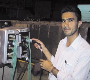
There are currently two students from IPM at CERN working on their PhD studies. They are gaining hands-on experience with detector design and construction, and are conducting LHC physics simulations for the CMS. Another Iranian student will join the team at the end of February.
For some years the Muon Collaboration – a group of particle and accelerator physicists from the US, Europe and Japan interested in neutrino factories and muon colliders – has been looking at the problems associated with operating high-gradient radiofrequency (RF) cavities at low frequencies (~200 MHz). In addition there has recently been considerable progress in the development of high-frequency, high-gradient cavities for linear colliders. So in order to review the common problems, whilst also aiming to communicate with the materials-science community, the idea of a workshop on high-gradient RF at Argonne National Laboratory began to form. Although we initially expected about 40 participants, almost 90 attended on 7-9 October 2003. The aim of the workshop was to try to identify the effects limiting gradients in a wide variety of different applications, and to connect these with the properties of the materials involved. Although most of the research in achieving high gradients in RF cavities has been in support of linear-collider proposals, similar challenges exist for klystrons and photoinjectors, and, more recently, the low-frequency cavities required for muon cooling.
While much of the discussion at the workshop concerned copper cavities, talks from KEK and DESY outlined the state of the art for superconducting RF. These talks implied that RF cavity surfaces could be made good enough to avoid breakdown processes, but that the procedures involved were expensive and the applicability to normal cavities was not always clear, as breakdown events seem to be produced from clean, smooth surfaces.
In a later session, measurements of direct current (DC) breakdown from Cornell, which resulted in “starbursts” identical to those seen in superconducting RF cavities, were shown. These events seem to connect the phenomena seen in DC, normal conducting and superconducting RF. There were also presentations of new data from Argonne on dielectric acceleration structures, and theoretical discussions on multipactoring in these structures.
Most of the workshop, however, was devoted to summaries of results from groups working on linear-collider development. The CLIC team from CERN reported the results of studies of refractory materials (molybdenum, tungsten), which seem to be able to survive higher fields than the copper usually used, but require much longer to condition. They also reported the frequency and temperature dependence of breakdown, showing data indicating that these two parameters do not have a strong effect.
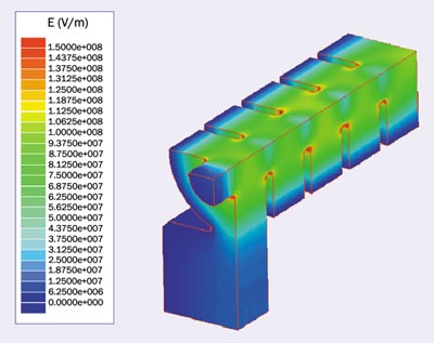
Participants from SLAC and KEK described the efforts being made for the Next Linear Collider (NLC) and Global Linear Collider (GLC) projects, respectively, to develop 11.4 GHz structures (figure 1) that operate stably at 65 MV/m with 400 ns pulses. Although the performance of these structures is approaching that required for a linear collider, the gradient limits are not fully understood. One limitation that has been overcome is thought to originate from pulse heating at the sharp-edged waveguide openings to the coupler cells. Pulse temperature increases above 100 °C appear to cause stress-related fracturing of the copper surface, which leads to breakdown. Rounding these edges to reduce the high peak magnetic fields that enhance the pulse heating has eliminated these events. Other breakdown mechanisms have been more elusive. In general the breakdown rate is seen to depend strongly on surface field for a given structure design, while breakdown-related damage appears to depend on the RF power level, independent of the design. At high power this damage leads to breakdowns on subsequent pulses (so-called “spitfests”), preventing further increases in gradient. For the three generations of structure designs that have been evaluated, this mechanism has limited input power levels to 60-80 MW, while the surface fields at this limit have varied by almost a factor of two (110 MV/m to 195 MV/m). The structure design efforts have therefore focused on reducing the input power for a given gradient, which is difficult due to efficiency and wakefield constraints.
KEK also reported on methods of surface treatment for the new S- and C-band accelerator structures they are building. The relative merits of diamond turning, chemical etching, electropolishing, vacuum baking, hydrogen baking and water rinsing are being systematically studied as part of their programme to upgrade the injector linac. A new method of smoothing, almost to the level of single atoms, was proposed by Epion Corporation. Gas-cluster ion beams (for example argon clusters at kilovolt energies) can produce very smooth surfaces on a variety of materials, with respectable erosion rates and coverage.
The Muon Collaboration reported on recent measurements in Lab G at Fermilab, which showed much new detail on dark-current production, as well as plans for the development of 201 MHz cavities, which are required by the Muon Ionization Cooling Experiment. In addition new data on high gradients in high-pressure cavities was presented by Muons Inc – a small business that was set up to perform R&D for muon cooling. A unique feature of this facility is the ability to produce very high magnetic fields in a variety of geometries.
Talks on modelling breakdown, from SLAC, Cornell and Argonne, looked at the process from a variety of directions. The most complete description of the development of RF breakdown events, which relies on an artificial injection of ions to get the process started, is a model that has been under development at Cornell for some time. Perry Wilson from SLAC summarized the many different mechanisms that have been shown to be involved in breakdown. Plasmas have been seen in many cavities and DC structures, and dark currents are known to be present at some levels in high-gradient cavities. Surface treatments affect the behaviour of the cavities, at least until the by-products of previous breakdown events dominate the surface, and surface heating due to wall currents and perhaps dark currents is known to contribute. In addition the plasma physics of ions, atoms and surfaces in high, rapidly changing electric fields is quite complex.
It seems that while many applications are limited by the same mechanisms, these mechanisms are not well understood. The designs for the SLAC/KEK 11.4 GHz NLC, CERN’s 30 GHz CLIC linac and the Muon Collaboration’s 805 and 200 MHz cavities seem to be affected by breakdown at operating fields consistent with the production, by field enhancements, of local surface electric fields of 5-10 GV/m. In addition to this mechanism, a separate failure mode connected with the local current density in the walls can occur – the phenomenon known as pulse heating. While breakdown in lower frequency cavities seems to be dominated by the high electric fields, pulse heating is more of a concern at higher frequencies.
There was considerable interest in isolating a “breakdown trigger”. In a session on modelling, there seemed to be some agreement that the missing element was a mechanism that would propel large numbers of atoms and ions into the volume of the cavity, to mix with the field-emitted electrons that are known to be there already.
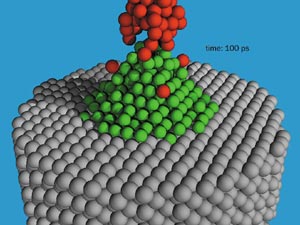
Work at Argonne over the past year has been aimed at identifying the breakdown trigger(s). Detailed measurements on dark currents at Fermilab have shown local fields of around 10 GV/m at emitters. Such fields can produce tensile stresses close to the tensile strength of copper, where fragments could break off and fly into the cavity. Also, some preliminary but very photogenic modelling of field evaporation (figure 2), seems to show that large fluxes of single atoms, ions and clusters could be injected into the cavity volume at the appropriate electric field and temperature. The effects of grain boundaries and defects also seem to be important (figure 3). At the high current densities present in high-frequency cavities, the resistivity of defects would produce very high local ohmic heating densities (and electric fields) in the surface of the material.
The surfaces that exist in cavities are complex, both structurally and chemically, and not completely understood, so continued effort will be required to progress further. Although the priorities are not entirely clear, it seems as if a variety of material-science measurements could begin to provide useful information on how some of the proposed trigger mechanisms for breakdown might actually work. There was some talk about the measurements that should be made and who might be involved in them. There was also discussion of the scope of current experimental and theoretical programmes that are aimed at improving cavity performance.
While a complete description or explanation of breakdown remains to be found, the workshop began to show how processes at surfaces and surface properties could influence the phenomenon. Ultimately, the relevant question is how much control is it possible to have over breakdown, and the answer will require some aggressive multidisciplinary research and development.
It is generally considered that the starting point for the Large Hadron Collider (LHC) was an ECFA meeting in Lausanne in March 1984, although many of us had begun work on the design of the machine in 1981. It took a very long time – 10 years – from this starting point for the project to be approved. During most of this time Giorgio Brianti led the LHC project study. However, we should not forget the enormous debt we owe to Carlo Rubbia in the second half of that decade for holding the community together behind the LHC against all the odds.
The first project approval came in December 1994, although under such severe financial constraints that we were obliged to make a proposal for building the machine in two stages. This would have been a terrible thing to do, but at that point we had no alternative. However, after a major crisis in 1996, when CERN had a rather severe budget cut, at least the constraints on borrowing were relaxed and a single-stage machine was approved. The first operation of the LHC is now foreseen for spring 2007. It has been a very long road indeed.
It is clear that building the LHC is a very challenging project. It is based on 1232 double-aperture superconducting dipole magnets – equivalent to 2664 single dipoles – which have to be capable of operating at up to 9 T. We were doing R&D on these magnets in parallel with constructing the machine and the experimental areas. This was not just a question of building a 1 m scale model with the very skilled people here at CERN, but of being able to build the magnets by mass production, in an industrial environment, at an acceptable price. This is something we believe we have achieved.
The machine also incorporates more than 500 “two-in-one” superconducting quadrupole magnets operating at more than 250 T/m. Here, our colleagues at Saclay have taken on a big role in designing and prototyping the quadrupoles very successfully. There are also more than 4000 superconducting corrector magnets of many types. Moreover, operating the machine will involve cooling 40,000 tonnes of material to 1.9 K, when helium becomes superfluid. An additional challenge has been to build the machine in an international collaboration. Although usual for detectors, this was a first for the accelerator community, and it has proved to be an enriching experience.
The production of the superconducting cable for the dipoles has driven the final schedule for the LHC, because we have to supply the cable to the magnet manufacturers. We could not risk starting magnet production too early when we were not sure that we could follow it with cable production. Figure 1 shows the ramp-up of cable production, which has now reached the required plateau. The final schedule for machine start-up in spring 2007 was fixed once we were confident of reaching this goal. This schedule is also well-matched to the construction of the detectors.
The next step is the serious production of the dipoles, with installation in the tunnel starting in January 2004 and finishing in summer/autumn 2006. The “collared coils” – more than half the work on the dipoles – are now being made at the rate we need. These are assembled into the cold masses, which are delivered to CERN where they are installed in their cryostats, tested and stored. More than 100 dipole cold masses are now at CERN, and we are confident that we will be very close to the final date for installation.
At the same time the infrastructure of the tunnel is being prepared for the installation of the superconducting magnets. Sector 7-8, the first sector to be instrumented, now has its piping and cabling installed. The next step is the installation of the cryoline, to provide the liquid-helium refrigeration. We are now looking forward to as smooth a passage as possible from installation into commissioning.
The LHC is a very complicated machine, and its operation presents many challenges. The most fundamental concern is the beam-beam interaction and collimation. In designing a particle accelerator, we try to make sure that the magnets have as little non-linearity as possible: that is, they have pure dipole and quadrupole fields. We then introduce controlled non-linearities – sextupoles to control chromatic aberrations and octupoles to give beam stability (Landau damping). We want smooth, distributed non-linearity, not a “lumped” linearity at one point in the ring. So we take a great deal of care, but then we are stuck with what we absolutely do not want – the beam-beam interaction itself. When the beams are brought into collision, a particle in one beam sees the Coulomb field of the other beam, which is strongly non-linear and is lumped – in every revolution the particle sees the beam-beam interaction at the same place. This produces very important effects, which I shall describe.
First, however, I should mention that the conversion of the Super Proton Synchrotron (SPS) into a proton-antiproton collider was a vital step in understanding this phenomenon. Indeed, it is not generally known what a step into the unknown we took with the collider. In this machine the strength of the beam-beam interaction, which we call the beam-beam “tune shift”, was very large, much larger than at the Intersecting Storage Rings (ISR). The collider was to operate in a domain where only electron-positron machines had worked, and these machines have the enormous advantage of strong synchrotron-radiation damping: particles that go through large amplitudes are “damped” into the core of the beam again. So we were going to operate a machine with no damping and a strong beam-beam effect. (Indeed, tests at SPEAR at lower and lower energies with reduced damping showed catastrophic effects, which when extrapolated indicated that the proton-antiproton collider could never work!)
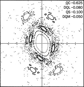
Figure 2 shows the effects in a simulation of the transverse phase space (the position-velocity space) of a particle in a perfect machine, apart from the beam-beam interaction. Because of the strong nonlinearity of the beam-beam interaction, particle motion can become chaotic and unstable at large amplitude. This was a real worry at the proton-antiproton collider, which proved to be an absolutely essential prototype for defining the parameters of the LHC. We have designed the LHC to beat this effect by sitting in a very small corner of “tune space” with very precise control in order to stay away from high-order resonances, although the beam-beam interaction will always be a fundamental limit.
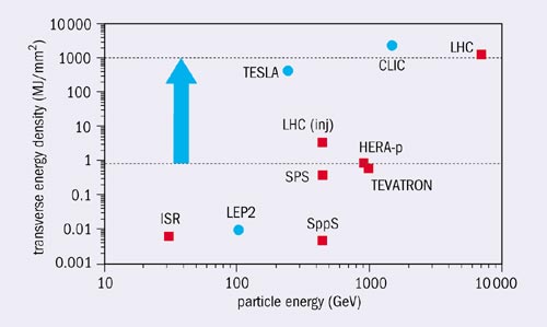
A second major challenge of operating the LHC concerns collimation, which is needed to remove halo particles from the beams to avoid their touching the superconducting magnets, and to control the background in the detectors. We also need collimation to protect against fault conditions – the stored energy in the nominal LHC beam is equivalent to 60 kg of TNT! If there is a fault the beam will be kicked out, and for that there is a 3 µs hole in the bunch spacing to allow the field in the kicker magnets to rise. If there is a misfiring particles will be lost as the kickers rise, and the collimators can melt, so they have to be very carefully designed.
Already, at less than 1% of its nominal intensity, the LHC will enter new territory in terms of stored energy. It is two orders of magnitude more in stored beam energy, but the beam-energy density is three orders of magnitude higher (figure 3) because as the beam is accelerated it becomes very small. To cope with this we have designed a very sophisticated collimation system. At injection the beam will be big, so we will open up the collimators to an aperture of about 12 mm, while in physics conditions the aperture of the beam will be 3 mm – the size of the Iberian Peninsula on a €1 coin. The beam will be physically close to the collimator material and the collimators themselves are up to 1.2 m long.
We are now on the final stretch of this very long project. Although there are three-and-a-half years to go, they will be very exciting years as we install the machine and the detectors. It is going to be a big challenge both to reach the design luminosity and for the detectors to swallow it. However, we have a competent and experienced team, and we have put into the design 30 years of accumulated knowledge from previous projects at CERN, through the ISR and proton-antiproton collider. We are now looking forward to the challenge of commissioning the LHC. It will be there in spring 2007.
•This article is based on a talk given at the symposium held at CERN in September 2003, “1973: neutral currents, 1983: W± and Z0 bosons. The anniversary of CERN’s discoveries and a look into the future.” The full proceedings will be published as volume 34 issue 1 of The European Physical Journal C. Hardback ISBN 3540207503.
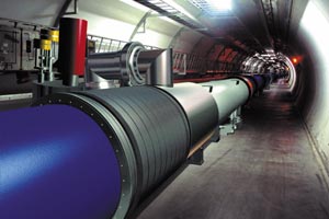
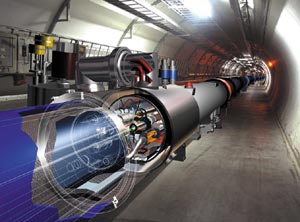
Since autumn 2003 people travelling between CERN’s two main sites in France and Switzerland have begun to notice a number of strange traffic jams, which are increasingly testing the nerves of impatient drivers. Lorries 16 m long with special cradles to transport 30 tonnes of equipment are now routinely entering Point 18 to unload their precious cargo: the main superconducting dipole magnets that will eventually fill more than 20 km of the 27 km ring of the Large Hadron Collider (LHC), and which will operate at fields in the range 8-9 T at 1.9 K. Following an R&D phase of more than 10 years, the ramping up of dipole production, which was long awaited by many and never even believed possible by the sceptics, has definitely begun with a pace that is now more than one magnet per working day. The last week of October 2003 scored the record so far, with eight dipoles being delivered between the Monday and the Friday.
Production overview
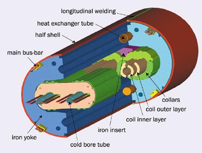
Three companies are charged with the construction of the LHC’s superconducting dipoles: the French consortium Alstom MSA- Jeumont, the Italian firm Ansaldo Superconduttori and the German company Babcock Noell Nuclear. Each has been engaged to provide CERN with one-third of the main dipole “cold masses” (figure 1). CERN is providing all the main components, some of the main construction tools and testing instruments, and the necessary engineering and technical support to make sure that the work done in industry complies with the tight technical specifications.
The process of magnet manufacturing can be split into two main activities: the production of the collared coils and the cold-mass assembly. The collared coils consist of eight coil layers that are wound with NbTi superconductor – the heart of the LHC – together with the collars that contain most of the magnetic forces, the cold-bore tubes where beam circulates and the heaters that protect the coil after a quench (the irreversible transition that brings the conductor to a resistive, normally conducting state). Once assembled, the coils are subject to magnetic measurements and stringent electrical checks.
The magnetic circuit is completed by assembling the flux return iron yoke around the collared coils and enclosing everything in the outer shrinking cylinder, which also serves as a superfluid helium vessel. Operations are then performed on the magnet extremities, including the electrical connections, the assembly of the corrector magnets, the insertion of the heat exchanger tubes that remove heat from the superfluid helium bath, the welding of the end covers that constitute the helium enclosure in the longitudinal direction, and many other welding and finalization operations. Finally, electrical tests, magnetic and curvature measurements, and leak tests are mandatory before the magnet can be dispatched to CERN.
One of the problems with the industrialization of the LHC dipole construction is the long lead time between the decision to implement a change and its validation in a cold test. This was more than two years during the prototype phase and more than one year in the so-called “preseries” phase. The last major design change was the choice of austenitic steel for the collars, in 1999, but further improvements such as the final design of the end spacers came as late as 2001. So the strategy for reaching a reasonable price both for CERN and the companies was to sign first contracts in 2000 for 3 x 30 preseries dipoles, with a tender for the series production in 2001. The tender process ended in spring 2002 with the signing of three contracts for the series production of 3 x 386 dipoles. Together with the preseries magnets, this makes a total of 1248 magnets, of which 1232 are destined for the tunnel, to be delivered by summer 2006. By summer 2001 only a few magnets had actually been built, and companies were not at all comfortable quoting for the series. However, through a collaborative negotiation, CERN and the companies arrived at a reasonable solution, although the figures for the various operations were at the time more of an educated guess than a proven reality.
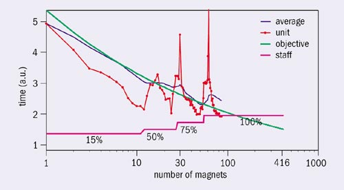
Now the preseries production is over and all three companies are well inside the series contract, so it is interesting to review where we are in terms of the industrialization of the process. Figure 2a shows the time needed for one company to complete a collared coil, compared with the so-called learning curve predicted at the time of the tender. On average, the process follows the prediction remarkably well. This is a sign that the process is well under control, which is of paramount importance for two reasons. First the collared coil is the heart of the magnet. Quench performance and field quality depend mainly on this part of the assembly. This point is made even more important by the time lag between collared-coil construction and the cold test (which is on average 10 months at present). Second the collared coils represent about 60% of the assembly cost and more than 70% of the total value of a dipole (mainly because of the superconducting cable cost).
The good performance shown in figure 2a, and the impressive stock of coils now at the suppliers (see figure 2b), is the fruit of a long R&D process in which the collared coils were always manufactured by industry. The continuity of the work on this part of the magnet system made this quick ramping up of production possible, while maintaining good quality – a marriage that is not at all automatic. The effect of training new people for the increased production is quickly absorbed, as shown in figure 3, where the construction time of one pole for one manufacturer is indicated. Coil quality shows some correlation with the recruitment of new staff and with the introduction of new tooling.
Welding and curvature
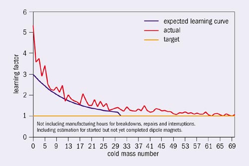
Figure 4 shows the graph comparable to figure 2a but for cold-mass assembly. Here the situation is not as advanced as for the collared coils, although the target has almost been reached. The cold-mass assembly was in fact undertaken at CERN in the Magnet Assembly Facility (building 181) until the end of 2001, and was transferred to industry only in 2002. Needless to say, transferring the appropriate technology took more time and effort than planned, with two points in particular impeding a smooth progression to the manufacturing process. The first concerned the longitudinal welding of the half shells around the yoke (see figure 1). This welding is done under a large press where the magnet is bent and so curves slightly downwards, i.e. it is rotated by 90° with respect to the final position in the tunnel. Secondly, the extremities of the magnets are very demanding and must be accurately positioned to allow fast and safe interconnections to be made by an automated procedure in the tunnel. This means that the curvature of the magnet has to stay within tight tolerances.
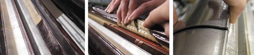
The longitudinal welding of the 10 mm thick half shells is carried out in four passes, the first being done with Surface Tension Transfer (STT) technology (see “Welding and curving the half shells” box). This rather new process invented by Lincoln Electric is a world first for this type of welding. While the process was selected using a prototype machine in the Magnet Assembly Facility at CERN, it could only be set up on the actual presses in 2002. A CERN task-force worked intensively on this problem with the dipole manufacturers and welding experts, and now the time for longitudinal welding has been significantly reduced. One company has shown itself to be capable of routinely welding 4.5 magnets a week; to remain within the LHC delivery plan the required weekly peak rate is three to four. This progress has also been made possible by the improvement in welding quality: the number of welding repairs went down by an order of magnitude after May 2003. While improvements still remain to be made in some areas, we think that the solution adopted is finally paying off.
The curvature of the magnets has an important effect on the quality of the beam deflection, due to the small aperture of the magnets. The size of the coil bores of 56 mm is much less than in any other project. Furthermore, we need to position the corrector magnets attached to the magnet ends within a very tight tolerance of ±0.3 mm. However, a study carried out on magnet alignment has slightly revised the end tolerances and established that about one-third of the magnets can have a tolerance in the body larger than was first thought. So the only open problem left is the accurate control of the position of the correctors, an issue for which several different solutions are under investigation.
The measurement of the geometry inside the 16 m long, 53 mm diameter cold-bore tubes has involved a special laser tracker developed by Leica in Switzerland, with the use at CERN contributing to its “debugging”. Both tubes are measured on each side four times during the construction of the magnet. At the time of the tender the duration of this operation had a large margin of uncertainty and initially the long time needed was an area of concern, both for the possible extra cost and timing of the project. Today the situation is much better and is steadily improving towards the objective.
The LHC dipoles are built following a strict quality-control based on an inspection and test plan containing 25 control points. In particular the magnetic measurements serve two different functions, with separate thresholds and modality of intervention. First the magnetic tests must steer the production of the magnets so that the bending strength and harmonics of the magnetic field remain inside the tough control limits imposed by the beam dynamics. The 10 month delay between construction of a collared coil and the low-temperature testing of the cold mass means that measurements must be made at ambient temperature in industry. This required fine tuning of the collared-coil cross-section during production, with two different interventions, to optimize the field harmonics.
The magnetic tests must also intercept assembly or component faults. While the warm tests cannot reveal all the faults – for example deficits in the critical current of the superconducting cable – so far three magnets have been disassembled based on field analysis and the predicted defect found (figure 5). The monetary value saved is already more than the whole investment in the warm magnetic measurements for the production so far. For this reason the magnetic measurements of the collared coils is a holding point, i.e. manufacturers can proceed with assembly only upon CERN’s explicit approval.
The performance in terms of the maximum field reached without a quench is good. More than half the magnets perform better than required, i.e. they are suitable for operation even at 9 T without needing systematic “re-training” in the tunnel. The other magnets do not have any problems in reaching the nominal field of 8.3 T without quenching, and only six magnets out of the 85 tested so far have lower performance (i.e. they may require training to reach nominal field). This is a mere 8%, which we hope to bring down to the target of 2% in the series production.
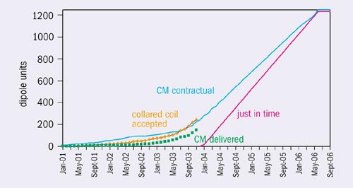
The delivery plan for the LHC dipoles depends critically on the timely delivery of the CERN-supplied components, beginning with the 1200 tonnes of superconducting cable at the heart of the accelerator. Figure 6 compares the delivery according to the contract (March 2002) with the actual results for approved collared coils and cold-mass delivery. Meeting the schedule is certainly a very difficult task, which can be jeopardized by many factors (first cables, and also collars, laminations and half shells are on the critical path). However, the changes in delivery slope last spring for collared coils and after summer for cold masses, show that magnets are really arriving at CERN, with the first octant having been delivered by 3 December 2003. Figure 7 shows the stock of cold masses that are almost ready at one of the manufacturers, blocked only by a temporary bottle-neck in transport. We had all better be prepared!
The classic “FODO lattice” – the basic combination of magnets that is repeated around the ring of most modern synchrotrons – contains not only focusing/defocusing magnets (main quadrupoles) and bending magnets (main dipoles) but also drift spaces between the magnets where the particles simply coast. These drift zones fulfil a very fundamental function, providing space for all the necessary connections for the beam chambers and power supplies, and also for the cryogenic systems, thermal shielding and vacuum vessels in the case of superconducting machines such as the Large Hadron Collider (LHC). However, because the drift space does not provide beam bending strength, it is wasted space in terms of achieving the highest beam energy in the ring. So one of the design requirements for circular accelerators and storage rings that are optimized for high beam energy is to minimize the ratio of drift-to-magnetic length in the machine arcs. This implies strong constraints on the systems located in the drift spaces, such as the thermal contraction/expansion compensation system, the radiofrequency (RF) contacts between the beam screens, the joints of the superconducting bus-bars, etc.
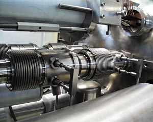
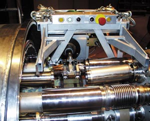
In the LHC, despite the machine’s complexity, the interconnections have been optimized to the extent that they will occupy only 3.7% of the accelerator length in the arcs and associated dispersion suppressors. (The machine consists of eight bending arcs, generally with dispersion suppressor sections located at either end of the arc to reduce the horizontal dispersion in the beams.) Figures 1 and 2 show the crowded interconnection region planned for the final machine and as already implemented in a prototype.
Such an achievement has had its price, however. As a result of a tight mathematical optimization, the components of the thermal contraction/expansion compensation system – the expansion bellows, which are composed of very thin corrugated shells (figure 3) – have been pushed to operate beyond the elastic limit, where plastic deformation occurs. Thus, for the first time in the history of accelerators, the interconnection bellows “plastify” with every cycle of cool-down (to 1.9 K) and warm-up (back to 293 K), whereas the magnets stay “elastic”. This process is associated with the evolution of plastic strain fields in the “concertina” of the bellows convolutions, which is accompanied by micro-damage and, at low temperatures, a strain-induced phase transformation (from a face-centred-cubic to a body-centred-cubic material structure). To minimize the intensity of this phase transformation, the bellows convolutions are made from a special “medical” grade of stainless steel. Figure 4 shows typical hysteresis curves, indicating the dissipation of energy due to plastic deformation during cycling between room and low temperatures. To obtain a reliable performance of the expansion bellows, these phenomena were all carefully modelled and tested at room and cryogenic temperatures. As the number of these components in the LHC exceeds 20,000, a statistical check of their reliability is performed, based on accelerated life testing of 1% of the components.
Another important feature of the interconnection zones concerns the joints between the superconductors. These joints, or splices, comprise connections both between the Rutherford-type superconducting cables powering the main magnets and between the small superconducting bus-bars that power the corrector magnets (figure 5). Each joint contains two overlapping superconductors separated by a strip of Sn96Ag4 or a thin layer of copper (depending on the joining technology), so the dissipation of energy due to heating losses is localized in this non-superconducting layer. While typical resistances of the joints between Rutherford-type superconductors remain below 0.6 nΩ at 1.9 K, the joints located in the corrector circuits show some 3 nΩ of resistance. Given the total number of joints, the maximum dissipation of energy per interconnection zone (if all systems are simultaneously powered) amounts to around 670 mW at 1.9 K (in a dipole-quadrupole interconnection). Thus a large fraction of the total energy dissipated at low temperatures into the coolant (superfluid helium) is localized in the electrical interconnections between the main LHC magnets, and the amount of energy that can be “produced” in the interconnections in this way is severely limited by the thermodynamic budget of the LHC.
In view of the severity of the various criteria that the LHC interconnections must satisfy, a rigorous reliability analysis is a must. The target set for the availability of all the LHC interconnections (around 1700 zones) is based on the assumption of at most one short intervention (10.5 days) per 10 years of LHC operation. This ambitious goal implies that the availability of the LHC interconnections for the entire system must be equal to 99.5%. Generally, there are three groups of components subject to failure in the interconnections: the compensation system (expansion bellows), the connections of the superconductors (splices) and the RF contacts. Assuming that the expected availability is apportioned to each family of components on an equal basis, and given the number of interconnections in the LHC, the expected reliability level for one interconnect (per system) is 99.9999%.
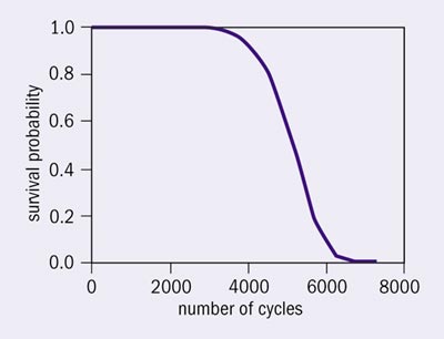
The LHC interconnections will consist of a total of around 250,000 components of different size and some 123,000 connections will be needed to integrate all these components. The main objective of the Quality Assurance Programme for the LHC interconnections is to minimize the risk of frequent failures of the critical components and to reduce the number of interventions. Figure 6 shows a typical plot indicating the measured reliability of one of the expansion bellows for the beam vacuum interconnects. Since the theoretically expected number of thermal cycles (including quenches) in the LHC lifetime does not exceed 50, the corresponding reliability of this component, i.e. the probability of survival, is very high and close to 100%.
The interconnections are one of the few systems for the LHC that will be almost entirely assembled in the tunnel (under the supervision of the LHC Interconnections Section) and not in laboratory conditions. Therefore, to achieve the target availability for the interconnection zones, a strict quality-control procedure has to be applied during the assembly process. This function will be fulfilled by a team of physicists and engineers (see “The Polish connection” box), who will check the interconnections one by one before the final closure of the accelerator. This “debugging” of interconnection zones aims to eliminate the errors in the connections that might jeopardize the electrical, cryogenic or mechanical functions of the machine. Given the total of around 123,000 connections – and a typical error rate during the assembly of complex systems of 0.3%, the number of possible errors to be eliminated reaches some 370. This alone is a sufficient reason to focus a great deal of attention on the complex interconnection systems located between the LHC superconducting magnets.
To provide the best experiences, we use technologies like cookies to store and/or access device information. Consenting to these technologies will allow us to process data such as browsing behavior or unique IDs on this site. Not consenting or withdrawing consent, may adversely affect certain features and functions.
Functional
Always active
The technical storage or access is strictly necessary for the legitimate purpose of enabling the use of a specific service explicitly requested by the subscriber or user, or for the sole purpose of carrying out the transmission of a communication over an electronic communications network.
Preferences
The technical storage or access is necessary for the legitimate purpose of storing preferences that are not requested by the subscriber or user.
Statistics
The technical storage or access that is used exclusively for statistical purposes.The technical storage or access that is used exclusively for anonymous statistical purposes. Without a subpoena, voluntary compliance on the part of your Internet Service Provider, or additional records from a third party, information stored or retrieved for this purpose alone cannot usually be used to identify you.
Marketing
The technical storage or access is required to create user profiles to send advertising, or to track the user on a website or across several websites for similar marketing purposes.