Comsol -leaderboard other pages

Topics

ATLAS: A titan fit for the LHC (archive)

CCAtl1_10_08

In Greek mythology, Atlas was a Titan who had to hold up the heavens with his hands as a punishment for having taken part in a revolt against the Olympians. For LHC, the ATLAS detector will also have an onerous physics burden to bear, but this is seen as a golden opportunity rather than a punishment.

The major physics goal of CERN’s LHC proton–proton collider is the quest for the long-awaited “Higgs” mechanism, which drives the spontaneous symmetry breaking of the electroweak Standard Model picture. The large ATLAS collaboration proposes a large general-purpose detector to exploit the full discovery potential of LHC’s proton collisions. LHC will provide proton–proton collision luminosities at the awe inspiring level of 1034 cm–2 s–1, with initial running in at 1033. The ATLAS philosophy is to handle as many signatures as possible at all luminosity levels, with the initial running providing more complex possibilities.

The ATLAS concept was first presented as a letter of intent to the LHC Committee in November 1992. Following initial presentations at the Evian meeting in March of that year, two ideas for general-purpose detectors, the ASCOT and EAGLE schemes, merged, with Friedrich Dydak (MPl Munich) and Peter Jenni (CERN) as ATLAS co-spokesmen.

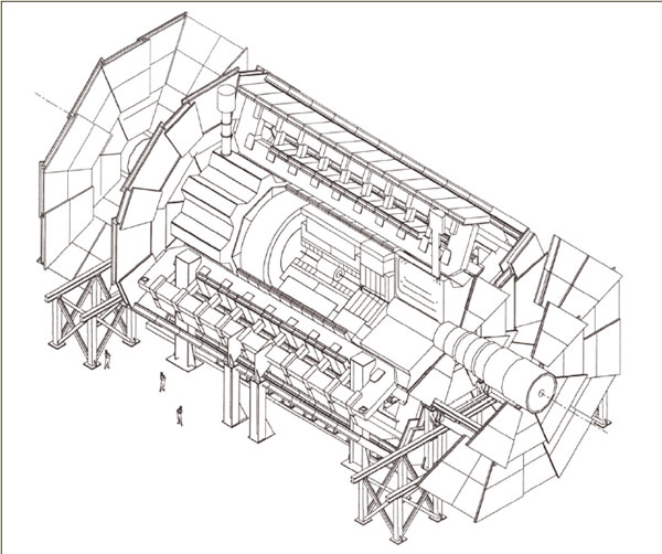
Since the initial letter of intent presentation, the ATLAS design has been optimized and developed, guided by physics performance studies and the LHC-oriented detector R&D programme. The overall detector concept is characterized by an inner superconducting solenoid (for inner tracking) and large superconducting air-core toroids outside the calorimetry. This solution avoids constraining the calorimetry while providing a high-resolution, large acceptance and robust detector.

The outer magnet will extend over a length of 26 m with an outer diameter of almost 20 m. The total weight of the detector is 7000 tonnes. Fitted with its endcap toroids, the outer magnet alone will weigh 1400 tonnes.

Designs on calorimetry

To achieve its basic aims, the ATLAS design has gone for very good electromagnetic calorimetry for electron and photon identification and measurements, complemented by complete (hermetic) jet and missing energy calorimetry; efficient tracking at high luminosity for lepton momentum measurements, for heavy quark tagging, and for good electron and photon identification, as well as heavy-flavour vertexing and reconstruction capability; precision muon-momentum measurements up to the highest luminosities and very low transverse-momentum triggering at lower luminosities. Other overall design aims include large angular coverage together with triggering and particle-momentum capabilities at low transverse momenta.

The inner detector is contained in a cylinder 6.8 m long (with a solenoid of length 5.3 m) and diameter 2.3 m, providing a magnetic field of 2 T. Design of the coil is being developed by the Japanese KEK Laboratory. Reflecting LHC’s bold physics aims and the pace of detector R&D, this inner detector is packed with innovative tracking technology (compared with existing major detectors), including high-resolution pixel and strip detectors inside and straw tubes with transition radiation capability farther away from the beam pipe. Finest granularity will be provided by semiconductor pixel detectors immediately around the beam pipe, providing about a hundred million pixels. With this technology moving rapidly, the final solution will benefit from ongoing R&D work.

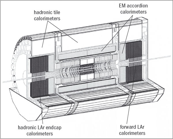
Surrounding the tracking region will be highly granular electromagnetic-sampling calorimetry, probably based on liquid argon (however, studies on an alternative liquid-krypton scheme are still in progress), contained in an “accordion” absorber structure in a cylinder 7 m long and 4.5 m across, plus two endcaps. The inner solenoid coil is integrated into the vacuum vessel of the calorimeter cryogenics, reducing the amount of material that emerging particles have to cross.

Liquid argon is used for both electromagnetic and hadronic calorimetry in the endcaps of the calorimeter, the former arranged in a “Spanish fan” geometry to cover all azimuthal angles without cracks, the latter in a wheel-like structure using copper absorber. Integrated into the endcaps is the forward calorimetry based on an array of rods and tubes embedded in a tungsten absorber some 5 m from the interaction point.

The bulk of the hadronic calorimetry is provided by three large barrels of a novel tile scintillator with plastic scintillator plates embedded in iron absorber and read out by wavelength-shifting fibres. The tiles, laid perpendicular to the beam direction, are staggered in depth to simplify construction and fibre routing. The total weight of the calorimetry system is 4000 tonnes (the entire UA1 detector that ran at CERN’s proton–antiproton collider for a decade and was considered a big detector in its time, weighed 2000 tonnes).

The air-core toroid magnet, with its long barrel and inserted endcaps, generates a substantial field over a large volume but with a light and open structure that minimizes troublesome multiple scattering. The toroid route was chosen because this geometry features the magnetic field perpendicular to the particle, and avoids large volumes of iron flux return. The French Saclay Laboratory is responsible for the barrel and the British Rutherford Appleton Laboratory for the endcaps.

lnterleaved with the main air-toroid magnet will be the muon chambers, the last outposts of ATLAS. These chambers, arranged in projective towers in the barrel region, are diametrically 22 m apart, with the central muon barrel extending 26 m and forward muon chambers 42 m apart, along the beam direction. Cathode-strip chambers will be used in the highest-rate environment close to the beam direction, supplemented farther out by “monitored” drift tubes – pressurized thin-wall tubes arranged in several layers.

Overall, ATLAS so far involves some 1500 scientists and engineers representing 140 institutions in 31 countries (including 17 CERN member states). The participation of non-member state groups is still subject to the satisfactory establishment of bilateral agreements between CERN and the appropriate funding agencies. However, their potential involvement in ATLAS is already woven deeply into the fabric of the collaboration.

For example, semiconductor strips for the inner detector could involve teams from institutes in Australia, Canada, the Czech Republic, Finland, Germany, Japan, Norway, Poland, Russia, Sweden, Switzerland, the UK and the US, while the scintillator tiles could involve Armenia, Brazil, the Czech Republic, France, ltaly, Portugal, Romania, Russia, Spain, Sweden, CERN and the US.

In addition to the 7000 tonnes of ATLAS hardware, a major effort is also required for software and data acquisition. To handle ATLAS data, the first-level trigger, which identify unambiguously which event crossing is responsible for the event, operates at the full-bunch crossing rate of 40 MHz (one bunch every 25 ns). It takes about 2 μs for the first-level trigger information to take shape and be distributed. During level-1 trigger-processing time, all data is held in pipelines prior to output at 100 kHz for subsequent processing at level 2. During these 10 ms, the level-2 processors look at subsets of detector data before passing it on for final processing (at about 1 kHz) at level 3, where complete event reconstruction becomes possible. Trigger processors at all three levels will be programmable.

• June 1995 p9 (abridged).

Tiles and accordions

CCAtl2_10_08

Design work and prototyping is well under way for the modules that will make up the ATLAS detector. One feature of the design stresses very good electromagnetic calorimetry for electron and photon identification and measurements, complemented by accurate measurements of hadronic jets and missing energy.

Arranged as a conventional central barrel with two endcaps, the inner part (including endcaps) uses the very-radiation-resistant liquid argon technique for electromagnetic measurements, contained in a 13 m long cylinder with outer radius 2.25 m, surrounded by less expensive iron-scintillator tiles sampling calorimetry for the hadronic part, extending to a radius of 4.25 m.

In the inner part of the endcaps, liquid argon is also used for the hadronic calorimeter. Special requirements are needed for the forward calorimeter around the beam pipe, about 5 m from the collision point. Fully integrated with the endcaps, liquid argon is again the sampling medium of choice.

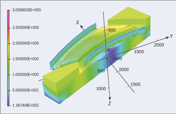
For the electromagnetic liquid-argon part, the 1024 lead–stainless steel converters of the sampling calorimeter are arranged in a novel corrugated “accordion” structure, with plates following the direction of the emerging secondary particles.

The barrel hadronic calorimetry is provided by an active medium of 3 mm-thick scintillator tiles, interleaved with absorber in the form of 14 mm steel sheets, and fashioned as a large 2500-tonne cylinder to surround the liquid argon barrel and endcaps. Full-scale prototypes under test show promising energy resolution.

• April 1997 pp5–6 (abridged).

Early days: The challenges of the LHC (archive)

CCcha2_10_08

It is generally considered that the starting point for the Large Hadron Collider (LHC) was an ECFA meeting in Lausanne in March 1984,although many of us had begun work on the design of the machine in 1981. It took a very long time – 10 years – from this starting point for the project to be approved. During most of this time Giorgio Brianti led the LHC project study. However, we should not forget the enormous debt we owe to Carlo Rubbia in the second half of that decade for holding the community together behind the LHC against all the odds.

The first project approval came in December 1994, although under such severe financial constraints that we were obliged to make a proposal for building the machine in two stages. This would have been a terrible thing to do, but at that point we had no alternative. However, after a major crisis in 1996, when CERN had a rather severe budget cut, at least the constraints on borrowing were relaxed and a single-stage machine was approved.

It is clear that building the LHC is a very challenging project. It is based on 1232 double-aperture superconducting dipole magnets – equivalent to 2664 single dipoles – which have to be capable of operating at up to 9 T. We were doing R&D on these magnets in parallel with constructing the machine and the experimental areas. This was not just a question of building a 1 m scale model with the very skilled people here at CERN, but of being able to build the magnets by mass production, in an industrial environment, at an acceptable price. This is something we believe we have achieved.

The machine also incorporates more than 500 “two-in-one” superconducting quadrupole magnets operating at more than 250 T/m. Here, our colleagues at Saclay have taken on a big role in designing and prototyping the quadrupoles very successfully. There are also more than 4000 superconducting corrector magnets of many types. Moreover, operating the machine will involve cooling 40,000 tonnes of material to 1.9 K, when helium becomes superfluid. An additional challenge has been to build the machine in an international collaboration. Although usual for detectors, this was a first for the accelerator community, and it has proved to be an enriching experience.

CCcha1_10_08

The production of the superconducting cable for the dipoles has driven the final schedule for the LHC, because we have to supply the cable to the magnet manufacturers. We could not risk starting magnet production too early when we were not sure that we could follow it with cable production. Figure 1 shows the ramp-up of cable production in 2002–2003.

The next step is the series production of the dipoles, with installation in the tunnel starting in January 2004 and finishing in summer/autumn 2006. The “collared coils” – more than half the work on the dipoles – are now being made at the rate we need. These are assembled into the cold masses, which are delivered to CERN where they are installed in their cryostats, tested and stored.

At the same time the infrastructure of the tunnel is being prepared for the installation of the superconducting magnets. Sector 7-8, the first sector to be instrumented, now has its piping and cabling installed. The next step is the installation of the cryoline, to provide the liquid-helium refrigeration. We are now looking forward to as smooth a passage as possible from installation into commissioning.

The LHC is a very complicated machine, and its operation presents many challenges. The most fundamental concern is the beam–beam interaction and collimation. In designing a particle accelerator, we try to make sure that the magnets have as little nonlinearity as possible: that is, they have pure dipole and quadrupole fields. We then introduce controlled non-linearities – sextupoles to control chromatic aberrations and octupoles to give beam stability (Landau damping). We want smooth, distributed non-linearity, not a “lumped” linearity at one point in the ring. So we take a great deal of care, but then we are stuck with what we absolutely do not want – the beam–beam interaction itself. When the beams are brought into collision, a particle in one beam sees the Coulomb field of the other beam, which is strongly non-linear and is lumped – in every revolution the particle sees the beam–beam interaction at the same place. This produces very important effects, which I shall describe.

First, however, I should mention that the conversion of the Super Proton Synchrotron (SPS) into a proton–antiproton collider was a vital step in understanding this phenomenon. Indeed, it is not generally known what a step into the unknown we took with the collider. In this machine the strength of the beam–beam interaction, which we call the beam–beam “tune shift”, was very large, much larger than at the Intersecting Storage Rings (ISR). The collider was to operate in a domain where only electron–positron machines had worked, and these machines have the enormous advantage of strong synchrotron-radiation damping: particles that go through large amplitudes are “damped” into the core of the beam again. So we were going to operate a machine with no damping and a strong beam–beam effect. (Indeed, tests at SPEAR at lower and lower energies with reduced damping showed catastrophic effects, which when extrapolated indicated that the proton–antiproton collider could never work!)

CCcha3_10_08

Figure 2 shows the effects in a simulation of the transverse phase space (the position–velocity space) of a particle in a perfect machine, apart from the beam–beam interaction. Because of the strong nonlinearity of the beam–beam interaction, particle motion can become chaotic and unstable at large amplitude. This was a real worry at the proton–antiproton collider, which proved to be an absolutely essential prototype for defining the parameters of the LHC. We have designed the LHC to beat this effect by sitting in a very small corner of “tune space” with very precise control in order to stay away from high-order resonances, although the beam–beam interaction will always be a fundamental limit.

A second major challenge of operating the LHC concerns collimation, which is needed to remove halo particles from the beams to avoid their touching the superconducting magnets, and to control the background in the detectors. We also need collimation to protect against fault conditions – the stored energy in the nominal LHC beam is equivalent to 60 kg of TNT! If there is a fault the beam will be kicked out, and for that there is a 3 μs hole in the bunch spacing to allow the field in the kicker magnets to rise. If there is a misfiring particles will be lost as the kickers rise, and the collimators can melt, so they have to be very carefully designed.

CCcha4_10_08

Already, at less than 1% of its nominal intensity, the LHC will enter new territory in terms of stored energy. It is two orders of magnitude more in stored beam energy, but the beam-energy density is three orders of magnitude higher (figure 3) because as the beam is accelerated it becomes very small. To cope with this we have designed a very sophisticated collimation system. At injection the beam will be big, so we will open up the collimators to an aperture of about 12 mm, while in physics conditions the aperture of the beam will be 3 mm – the size of the Iberian Peninsula on a €1 coin. The beam will be physically close to the collimator material and the collimators themselves are up to 1.2 m long.

We are now on the final stretch of this very long project. Although there are three and a half years to go, they will be very exciting years as we install the machine and the detectors. It is going to be a big challenge both to reach the design luminosity and for the detectors to swallow it. However, we have a competent and experienced team, and we have put into the design 30 years of accumulated knowledge from previous projects at CERN, through the ISR and proton–antiproton collider. We are now looking forward to the challenge of commissioning the LHC.

January/February 2004 p27 (abridged).

Based on a talk given at a symposium at CERN, published in Prestigious Discoveries at CERN. 1973 Neutral Currents 1983 W & Z Bosons (Springer 2003).

Early days: The Evian experiment meeting (archive)

CCcon3_10_08

As plans for the LHC proton collider to be built in CERN’s 27 km LEP tunnel take shape, interest widens to bring in the experiments exploiting the big machine. The first public presentations of ‘expressions of interest’ for LHC experiments featured on 5–8 March at Evian-les-Bains on the shore of Lake Geneva, some 50 km from CERN, at the special ‘Towards the LHC Experimental Programme’ meeting.

This event followed soon after CERN Council’s unanimous December 1991 vote that the LHC machine, to be installed in the existing 27 km LEP tunnel, is ‘the right machine for the advance of the subject and for the future of CERN’. With detailed information on costs, feasibility and prospective delivery schedules to be drawn up before the end of next year, and now with plans for experiments under discussion, the preparations for LHC move into higher gear. The Evian meeting was a public forum for a full range of expressions of interest in LHC experiments, setting the stage for the submission of Letters of Intent later this year and cementing the proto-collaboration arrangements.

Participants at the meeting also heard the latest news on LHC machine studies, and the thinking on preparations for experimental areas and LHC physics potential. As well as its main objective of proton–proton collisions, LHC also opens up possibilities for ion–ion collisions, for fixed-target studies and eventually for electron–proton collisions as well. Most of these areas were covered at Evian.

LHC beams can in principle collide at eight points. Four of these coincide with the four big experiments at the LEP electron–positron collider. Of the remaining four points, one, deep under the Jura mountains, will have to be used for an LHC ‘beam-cleaning’ system to ensure high performance by reducing troublesome beam halo. Another will be reserved for the beam dump where the LHC protons will be absorbed once the circulating beams are no longer required. This leaves room for two big new LHC-collider detectors, plus the potential of the existing LEP experimental areas, using either adapted LEP experiments or new apparatus mounted in push–pull to alternate with LEP running.

At Evian, four major detectors for studying proton–proton collisions were being tabled, three of which are new, and one a development from an existing LEP experiment. The ASCOT (Apparatus with SuperCOnducting Toroids) general purpose detector is proposed by a team from CERN, the UK (Edinburgh and Rutherford Appleton Laboratory), Germany (Wuppertal and Munich MPI and University), France (Saclay) and Russia (Moscow, Dubna and Protvino). It is based on a 24 m long superconducting toroid instrumented with drift tubes for precision muon detection.

Inside the magnet, the emphasis is on electrons, with a lead/liquid argon electromagnetic calorimeter, and tracking through interleaved layers of scintillators and transition radiation detectors, with semiconductor pads close to the beam pipe. A 1.5 T superconducting solenoid in front of the electromagnetic calorimeter distinguishes electrons and positrons. Hadron calorimetry uses iron and liquid argon.

The EAGLE (Experiment for Accurate Gamma, Lepton and Energy measurements) collaboration proposes a comprehensive detector to cover a wide range of physics, and already involves physicists from 14 CERN member states, plus Canada, Russia, Australia, Brazil and lsrael. EAGLE foresees a powerful inner-electron detector inside a 2 T central superconducting solenoid. The design features high-quality electromagnetic sampling calorimetry combined with fine-grained electron and photon preshower detection, a high-precision vertex detector for lower collision rates, hadron calorimetry and a conventional toroid muon spectrometer.

The Compact Muon Solenoid (CMS) LHC detector is designed to be compatible with the highest LHC collision rates, and is built around a 15 m long superconducting solenoid providing a 4 T field. The strong field gives relatively compact muon measurement. R&D work for the muon detectors is looking at resistive-plate chambers and parallel plate chambers for timing information and honeycomb-strip chambers and wall-less drift chambers for spatial information. The central tracker will use small cells, based on silicon (or gallium arsenide) strip detectors and microstrip gas chambers, to ensure good pattern recognition under the stringent LHC conditions. Also inside the coil is a high-resolution electromagnetic calorimeter and a hadron calorimeter. CMS involves a team from 12 CERN member states, plus Byelorussia, Bulgaria, Estonia, Georgia, Hungary, Russia and the US.

The L3 experiment at LEP was originally designed for use at both LEP and LHC, with a large experimental hall and magnet. Upgrade for LHC would involve improving the muon resolution, adding a fine-grain hadron calorimeter, increasing the magnetic field, and being able to lift the detector 120 cm from the LEP position to the LHC beams above. For the work, 39 institutes from the L3 LEP line-up have been joined by 20 more, mainly from China and the former Soviet bloc.

Supplementing the main proton–proton LHC programme are a range of other experiments, including fixed-target studies. Expressions of interest received so far include ideas for two neutrino experiments and three studies concentrating on CP violation in B-particle decays, one using a gas-jet target, one using extracted beams and one a colliding-beam setup.

Although not the spearhead of LHC physics, ion–ion collisions will still play a major role, continuing a CERN tradition in this field. For ion collisions, three teams are interested – one using CMS, another using the (suitably modified) Delphi experiment at LEP and a third using a new dedicated detector.

More than 600 members of the potential LHC user community met at Evian. Introducing the event, Organizing Committee chairman Gunter Flügge of Aachen traced the previous history of major international get-togethers and other milestones which have delineated LHC progress: from the 1984 Lausanne workshop where the LHC idea was launched, through the valuable 1987 recommendations of the CERN Long Range Planning Committee under the chairmanship of Carlo Rubbia, to the 1989 Barcelona meeting on Instrumentation Technology and the 1990 Aachen workshop to study the physics objectives. Wrapping up at Evian, CERN director-general Carlo Rubbia proposed an ongoing schedule for the selection of LHC experiments, with Letters of Intent to be submitted after the summer for selection at the end of the year. The selected experiments would then proceed with a full design report. Whatever the outcome of this selection, Evian will always be remembered as the stage where these ideas made their public debut.

• Compiled from April 1992 pp1–3 and May 1992 pp1–3.

The LHC sees its first circulating beam

At 10.28 am on 10 September, the first beam made the full 27 km journey around the LHC, travelling in a clockwise direction. Cheers and applause filled the CERN Control Centre (CCC) as two spots appeared on the screen, indicating that the beam had completed the full circle, from injection at Point 2 round to the same point. The emotion was echoed around CERN where staff and users had been watching events unfold via screens in the main auditorium and elsewhere, as well as in the control rooms of the LHC experiments. Also keenly watching the action were some 250 journalists attending the event, many in the Globe of Science and Innovation.

Delighted faces in the CERN Control Centre

It had taken the operations team in the CCC, just less than an hour to allow the beam to progress carefully, through one sector at a time. Finally, the beam made three circuits before the team decided to take a well-earned pause before starting the procedures for the beam travelling in the opposite direction. Then in the afternoon, again taking about one hour for the complete journey sector-by-sector, the first beam travelled anticlockwise all the way from injection at Point 7, finally making a total of two circuits.

Present in the crowd in the CCC, were all the directors-general of CERN who had watched over the proposals, approval and construction of the LHC. Herwig Schopper (1981–1988) had overseen the construction of the LEP collider, with its 27 km tunnel that the LHC now occupies; Carlo Rubbia had been a tireless and inspirational advocate for the machine (1989–1993); Chris Llewellyn Smith (1994–1998) had conducted the hard negotiations that led to the project’s approval in 1996; Luciano Maiani (1999–2003) was at the helm as major construction got under way; and Robert Aymar, the current director-general, has seen the project to its successful completion. The crowd also included Giorgi Brianti, the “father” of the machine with its unique twin-aperture, two-in-one magnet system.

Past director-generals who between them have seen the LHC dream become reality.

Only very careful planning and preparatory work had made it possible for the Operations Team to be able to propose starting up the machine under the eyes of the world’s media. Although common practice for the launch of space vehicles, for example, this was a “first” in the world of particle physics – and not without additional stress for the operators. From 9.00 am to 6.00 pm at CERN, regular live action from the CCC was broadcast by many TV channels. The journalists in the Globe were also able to attend a press conference in the afternoon, given by the current director-general, together with Llewellyn Smith, Rubbia, Schopper, Brianti, Evans, and Jos Engelen, CERN’S Chief Scientific Officer.

The sight of first beam marks the end of a long journey for the LHC project, from the first proposals in 1984 to the final hardware commissioning this past summer. It is also the first step in the process of bringing the LHC into operation. The next stage for the operations team will be to establish beams that circulate continuously, for hours at a time. The final step will be to commission the LHC’s acceleration system to boost the energy to 5 TeV per beam – the target energy for 2008, which will be a world record energy and another “first” for CERN.

Gas detectors advance into a second century

In 1908, Rutherford was the first to use a gas-filled wire counter to study natural radioactivity. To celebrate 100 years of gas counters, and in particular to look ahead to new developments in gas-based detectors, some 100 physicists gathered at Nikhef, Amsterdam, on 16–18 April. They were on a mission: to work towards the foundation of the RD51 collaboration, devoted to further research and development of micropattern gas detectors (MPGDs).

CCdet1_09_08

Fabio Sauli from the TERA Foundation and CERN reviewed how, in 100 years, gas detectors developed from Geiger counters to multiwire proportional chambers, drift chambers and time-projection chambers (TPCs) – detectors that are now widely used in high-energy and nuclear physics experiments. The need for gas detectors that could operate at high counting rates led to the development of micro-strip gas chambers. However, they proved difficult to operate in challenging conditions and were prone to aging and sparking. Nevertheless, the gas-detector community stood up to the challenge. The invention of MPGDs, such as the micromesh gaseous structure chamber (the MicroMegas) and gas-electron multiplier (GEM) detector, appears to have solved these problems.

Progress in MPGDs

These detectors have small avalanche gaps and therefore a rapid signal development, implemented in slightly different ways. In MicroMegas detectors the electron multiplication takes place in the narrow gap between a thin cathode mesh with holes and the anode. GEMs, on the other hand, have an insulating polymer foil with thin metal coatings on both sides, and the multiplication takes place in the holes in the foil. Such MPGDs are already in use in difficult environments, such as in the COMPASS experiment at CERN, and various ideas exist to develop MPGDs further into robust, economic, fast and, potentially, large-area tracking detectors with a low material budget (one-fifth to one-tenth of that in typical silicon detectors).

The workshop heard about progress towards various further improvements for MPGDs. Ioannis Giomataris of DAPNIA-Saclay presented new developments in MicroMegas detectors, such as bulk and large-area construction, and also spoke about various applications. Recent advances in thick GEM detectors formed the focus of the talk by Amos Breskin of the Weizmann Institute, while CERN’s Serge Duarte looked at how to make large GEMs. In a slightly different vein, Vladimir Peskov from CERN described work on resistive-electrode thick GEMS, which are designed to give higher gain without sparking.

With recent developments in silicon wafer processing technology it is now possible to grow the thin cathode grid of a MicroMegas detector right on top of a silicon pixel chip (figure 1). Such a set-up (known as “Ingrid”) integrates detector and read-out electronics optimally in one structure, as Victor Blanco Carballo from Twente University and Lucie de Nooij from Nikhef demonstrated (figure 2). Sparks in the narrow gap between the cathode and the anode can destroy the pixel chip, but Nicolas Wyrsch of the Institute of Microtechnology, Neuchatel, showed that with a layer of amorphous silicon on the pixel chip, the detector can withstand sparking.

There are numerous applications of MPGDs, a few of which were discussed during the workshop. In R&D studies, thick GEMs are used for the detection of single photons in Cherenkov imaging counters. At Jefferson Lab, a new multipurpose spectrometer is being developed, where GEMs could be used in particle tracking at high rates. GEMs are also being developed for digital hadron calorimetry in experiments proposed for the International Linear Collider (ILC) – a very high granularity can be achieved with small cells that are either “on” or “off”. Groups working on experiments for the ILC have in addition designed large TPCs with MPGD read-out, and both GEMs and MicroMegas are being considered for this role.

In other developments, MicroMegas detectors could read out a TPC for the Tokai-to-Kamioka experiment in Japan, or be used as muon detectors at high counting rates, such as in the upgrade of the ATLAS detector at CERN for the upgraded LHC, the Super-LHC (SLHC). A gas-pixel transition-radiation tracker based on MicroMegas is under study, and MicroMegas detectors are excellent technology choices for experiments that aim to detect rare events, such as searches for weakly interacting massive particles and solar axions, and studies of neutrinoless double beta-decay. MPGDs also have applications in astronomy and medicine as X-ray imaging detectors, and in neutron detection.

CCdet2_09_08

The workshop also discussed future read-out chips. The TimePix chip is derived from the Medipix2 chip, but with a time measurement for each pixel, which is an important asset for gas detectors. Michael Campbell from CERN talked about the Medipix3 chip, which is now under development, and Jan Timmermans of Nikhef discussed the requirements of TimePix-2, a successor of TimePix, and how this chip could be a general purpose read-out chip.

The RD51 collaboration

In a workshop at CERN in September 2007, participants realized that future progress in MPGDs would be best served by tighter collaboration. This led to the formation of a protocollaboration, working towards an R&D proposal: “Development of micropattern gas detectors technologies.” Now some 50 institutes in Europe, the US and Asia have declared an interest, and a proposal for this collaboration, RD51, was submitted to the LHC committee on 2 July, following the workshop at Nikhef where Leszek Ropelewski from CERN was elected spokesperson, and Maxim Titov of CEA-Saclay was elected co-spokesperson.

The objectives of RD51 are to form a technology-oriented collaboration; to share common investments and infrastructure, such as test beams, radiation facilities and production lines; to develop common standards; to optimize the communication and sharing of knowledge; and to collaborate with industrial partners. The collaboration intends to perform technological studies for the optimization and industrialization of each manufacturing technology, and to develop radiation-hard devices that can operate beyond the limits of present devices (e.g. for detector upgrades for the SLHC). In addition, RD51 will work towards the integration of detector-simulation software, such as Garfield and Magboltz, with Geant4. It will also study the synthesis of MPGD front-end electronics into a number of read-out approaches, optimize read-out integration with detectors, and develop large-area MPGDs with CMOS read-out.

• Slides from the workshop are available online at Indico: see indico.cern.ch/conferenceDisplay.py?confId=25069
The next RD51 workshop will take place in Paris on 13–15 October 2008. For further details, visit http://indico.cern.ch/conferenceDisplay.py?confId=35172

Energy options and the role of nuclear fusion

Chris Llewellyn Smith is no stranger to CERN. He served five years as director-general, from 1994 to 1998. During his mandate, LEP was successfully upgraded and the LHC project was approved. On his most recent visit to CERN, however, Llewellyn Smith did not address the audience gathered in the main auditorium on particle physics or high-energy accelerators. Instead, he talked about the shortage of energy sources in the world, a popular topic these days.

With the price of oil fluctuating, subjects such as “hydrogen-driven” cars, “solar-fed” devices and “biomasses” appear increasingly in newspapers and magazines, with various experts constantly presenting new scenarios. According to the International Energy Agency, a huge increase in energy use is expected in the coming decades. Most of it is needed to lift billions of people out of poverty, including more than 25% of the world’s population who still lack electricity.

Llewellyn Smith: from CERN to nuclear fusion.
Image credit: UKAEA.


According to Llewellyn Smith: “Fossil fuels supply 80% of the world’s primary energy. When they are exhausted, it currently looks as if much of their role will have to be taken over by nuclear fission (conventional nuclear reactors at first, then fast breeders when the cheaper uranium is exhausted), and possibly solar power, but this will need technological advances to decrease the cost, and in storage and transmission. And then, of course, we should use any alternative energy that works such as wind, biomasses and hydro. We also must become much more economical. For large-scale production power plants, we hope that a major role will be played by fusion.”

The idea of producing energy using nuclear fusion dates back to the early 1950s. About 20 years after its discovery, at the first Conference on the Peaceful Uses of Atomic Energy held in Geneva in 1955, Homi Bhabha said: “I venture to predict that a method will be found for liberating fusion energy in a controlled manner within the next two decades.” (Vandenplas and Wolf 2008). Unfortunately, after the first enthusiastic moments, major technological hurdles prevented fusion from becoming the easy option for energy supply that was originally expected.

Now the future of fusion is ITER, the joint international research and development project that aims to demonstrate the scientific and technical feasibility of fusion power. “The biggest fusion device in the world at the moment is the Joint European Torus, JET, at Culham in the UK,” explains Llewellyn Smith. “In order to show that fusion can really work, we need to build something that is twice as big in every dimension and that will be ITER. There are other devices currently being built in the world but they are all smaller, so there is no competition for ITER.” Europe, Japan, Russia, US, China, South Korea and India are all involved in the ITER project. “Between them,” continues Llewellyn Smith, “these countries are home to more than half the population of the world. So, this is really a global response to a global problem.”

CERN is directly contributing to support ITER through some recently signed agreements (CERN Courier May 2008 p26). “ITER is starting from nothing,” says Llewellyn Smith, who is currently chairman of the ITER Council. “They need experts in a large number of areas and CERN can help by making expertise available. Some of these areas, such as superconductivity, have been used in fusion but not on the scale that has been used at CERN. The expertise of CERN people will certainly help to build up the project and make it work quickly.”

Strong links between CERN and the fusion facilities also exist at a more managerial level. Llewellyn Smith was called to lead the UK nuclear fusion programme after his mandate at CERN and then obtained the chair of the ITER Council, whereas CERN’s current director-general, Robert Aymar, did quite the opposite and came to CERN after having led the ITER project. “The first example of exchange between CERN and fusion dates back to John Adams in the 1960s,” confirms Llewellyn Smith. “He was an engineer who went from building the PS to founding the Culham fusion laboratory, which I now direct, and then went back to CERN to build the SPS.”

Particle physics and fusion use similar techniques, such as superconducting magnets, high-vacuum systems, RF systems, and detectors that have to work with high levels of radiation. However, it is not only the development of new technologies that Llewellyn Smith brought from CERN to the fusion projects; it is also the experience of big international scientific projects. “I joined fusion at a time when Europe was trying to reach agreement to build ITER with the other members,” he continues. “The experience that I had negotiating to get the Americans, Japanese, Russians, Indians, Canadians etc involved at CERN, was valuable; I had dealt with many of the governments in ITER before, and even many of the same people.”

Big projects have high potential but they also bring a great deal of uncertainty concerning their feasibility, the huge amount of money they cost and their actual duration. ITER is not even a real fusion reactor yet, it is an experimental device. It will take at least 10 years to build it and another decade to understand its results, and only then might people start building an actual prototype power station. “The time-scale is slow,” confirms Llewellyn Smith. “It is slow because we are dealing with very difficult, large-scale, first-of-a-kind projects. In fact, it will take considerably more than 30 years before fusion can be rolled out on a large scale. A very good question is if it will still be needed. The answer is ‘yes’, because the energy need is going to increase and – even forgetting about CO2 and climate change – at a certain point there will be no oil, no coal, and no gas, and we will really need additional options. So we have to go on with fusion as fast as we can.” As it seems inevitable that the world’s remaining fossil fuels will be used, “developing the technology to capture and store the CO2, and then deploying it on a large scale, must be a priority” according to Llewellyn Smith.

A particular attraction of fusion is that it is environmentally responsible. “Fusion doesn’t produce CO2, and it’s not possible to have some sort of runaway reaction or explosion,” explains Llewellyn Smith. “Fusion reactors can have all sorts of problems but it is very difficult to imagine accidents that will harm people. Fusion uses tritium, which is of course radioactive, but the active amount in a fusion power station will be less than a gram. The walls of the reactor become radioactive, but by choosing the materials correctly, we can make sure that the radioactivity has a half-life of around 10 years. So, a fusion reactor will become radioactive but 100 years later you could recycle the material. Unless you burn it, the waste from a conventional nuclear reactor is radioactive for many thousands of years.”

Changes in energy sources in the long-term future will alter the political balance of the world. Wealthy countries whose internal economy depends on the oil trade may become less wealthy, and western economies based on the use and transformation of oil derivatives may suffer from the change in the global energy scene. “The problem we face today is that the very poor countries generally have very limited energy resources,” says Llewellyn Smith. “One quarter of the world’s population has no electricity at the moment. They need more energy to enjoy anything like what we would regard as an acceptable standard of living. We need some sort of solidarity, and equity.” He adds: “At the moment 80% of our energy comes from oil, coal and gas, which are going to end in the next decades. So the world is going to be different. I can’t predict what it will be like but the concern is to make sure that it is viable for everybody. It is unlikely that very high-tech solutions like fusion will become widely available in less wealthy countries. So maybe we in the developing world should be adopting such high-tech solutions and they should be using fossil fuels as long as they last. That is a political problem.”

Politics and the role of science: this is an interesting point. How much are scientists driven by politicians and vice-versa? “In the end politicians must make the decisions,” says Llewellyn Smith. “The responsibility for scientists is to make sure that decisions are made on the basis of true facts. Long-term projects are very difficult to deal with because politicians only tend to look until the next election. They are beginning to say the right things about climate change, but words are not enough. We cannot stop the consequences of the things we are already doing, which will happen (e.g. rising temperatures) during the next 20 to 30 years. As scientists, it is our duty to make sure that governments understand what the potential solutions are and what alternative solutions should be developed. Our responsibility is providing information in an easy and understandable form.”

The primary concern of scientists is to understand the world, not change it, but as Llewellyn Smith concedes: “As a by-product they can help to change and shape it; in fusion we are trying to help shape the world by providing another major energy option.”

The rise of the FFAG

The concept of fixed-field alternating-gradient (FFAG) accelerators was put forward in the early 1950s, as a possible way of applying the methods of strong focusing and phase stability to particle acceleration. An FFAG ring is a circular assembly of fixed-field magnets that strongly focus the accelerated beam, similar to that in an alternating-gradient synchrotron. However, as the magnetic field remains constant by definition, the beam spirals radially during the acceleration process, as in a cyclotron. Consequently, FFAGs feature magnets with a large transverse aperture and therefore high-beam acceptances in both momentum and space. Fast acceleration, high repetition rate and a large 6-D acceptance are the potential benefits of FFAGs that triggered their rebirth at the end of the 1990s, mainly in Japan. Since then the concept has been revisited in depth and this has led to a dual machine classification: scaling (invariant-focusing) FFAGs and non-scaling FFAGs.

In scaling FFAGs, the orbit shape and the optics of the beam are kept unchanged during the acceleration by applying a non-linear magnetic field of the form B = B0 (r/r0)k, where k is the field index. Scaling FFAGs may be seen as an evolution of the synchrocyclotron concept, but offering more flexibility and potentially better performance in various application domains. The Japanese have recently constructed prototypes of radial-sector proton rings following this concept. They showed that modern 3D computer-aided methods allow accurate and reliable design of the sophisticated non-linear FFAG magnets. They also led to the development of a broadband and high-gradient RF cavity technology that makes fast acceleration and high repetition rates possible.

CCffa1_09_08

In non-scaling FFAGs, on the other hand, the betatron tunes are allowed to vary during the acceleration process. This freedom opens up new concepts that have been investigated with the help of modern particle-tracking computing techniques. Under the hypothesis that the total acceleration time is kept sufficiently short, the fast crossing of betatron resonances should have little effect on the beam stability. This new regime is sometimes referred to as “curved linear acceleration”, meaning that there is no cyclic component in the beam motion equations. Non-scaling FFAGs tend to have much smaller transverse apertures than scaling machines.

FFAGs in Japan

The world’s first proton FFAG accelerator, the Proof-of-Principle FFAG (POP-FFAG) was built at KEK in Japan in 2000. At approximately the same time, researchers recognized that FFAG accelerators can feature rapid acceleration with large momentum acceptance. These are exactly the properties required for muon acceleration, for the production of medical proton beams and for accelerator-driven systems (ADS) for nuclear energy. To investigate this potential, a team at KEK developed the first prototype of a large-scale proton FFAG accelerator. In 2004, it successfully accelerated a proton beam up to 150 MeV with a repetition rate of 100 Hz. Since then, intensive studies and discussions have taken place and various novel ideas have emerged that have led ultimately to new application projects for FFAG accelerators at several institutes in Japan.

A team at the University of Kyoto has developed a proton FFAG accelerator for basic research on ADS experiments. Here, the beam is delivered to the existing critical assembly of the Kyoto University Research Reactor Institute (KURRI). The whole machine is a cascade of three FFAG rings (figure 1). The beam was recently successfully accelerated up to 100 MeV and the first ADS experiment is due to start this summer.

CCffa2_09_08

Medical applications of FFAG accelerators have also been proposed in two different fields: hadron therapy and boron neutron-capture therapy (BNCT). For BNCT, an accelerator-based intense thermal or epithermal neutron source has been developed at KURRI, using an FFAG storage ring with a thin internal beryllium target (figure 2). The growth of the beam emittance and the energy distortion caused by scattering in the target can be controlled using ionization cooling, a functionality that could not be used in a cyclotron owing to the lack of space. After completion of the whole system, recently the beam was successfully accumulated in the ring and neutron production has already been observed. This constitutes the first experimental demonstration of the efficiency of ionization cooling.

At the University of Osaka there is a proposal to build a highly intense muon source using the 50 GeV proton beam of the synchrotron at the Japan Proton Accelerator Research Complex. In the project, called PRISM, longitudinal phase-space rotation to narrow the initial energy spread of a muon beam by a scaling FFAG ring – featuring a large energy acceptance – has been developed to search for lepton-flavour violation in muon interactions. The ring consists of 10 magnets and 5 magnetic alloy RF cavities with a frequency and a gradient of 5 MHz and 200 kV/m, respectively.

The University of Kyusyu also has a new accelerator facility under construction. The main machine will be a 150 MeV proton FFAG accelerator whose design closely follows the one at KEK described above. This will be available for various applications, such as nuclear physics and material science.

EMMA in the UK

In the UK, non-scaling FFAGs are currently being studied for a variety of applications, including hadron therapy, ADS and the rapid acceleration of muons for a neutrino factory and a muon collider. The unique features of such machines mean that detailed development for these applications requires the construction of a proof-of-principle accelerator to explore in detail the beam dynamics to gain experience in the design and construction of non-scaling FFAGs, and to benchmark the computer codes employed in the studies.

This new machine, the Electron Model for Many Applications (EMMA) will be built at the Daresbury Laboratory of the Science and Technology Facilities Council (STFC). EMMA has been funded as part of the British Accelerator Science and Radiation Oncology Consortium (BASROC), which has also funded the design of a non-scaling FFAG, PAMELA, for the acceleration of carbon ions and protons for hadron therapy, and for studies of other potential applications of this technology.

EMMA will be a 10–20 MeV electron linear, non-scaling FFAG, designed with the necessary flexibility to allow the detailed studies required. In addition, it will use the linac for the Accelerators and Lasers In Combined Experiments (ALICE) project as an injector (figure 3). ALICE can deliver beams at any energy between 10 and 20 MeV, an important requirement for a complete study of resonance crossings in EMMA.

CCffa3_09_08

EMMA will use a doublet lattice and the ring will consist of 42 cells, each about 40 cm long. There will be 1.3 GHz RF cavities in every other cell, except around the injection and extraction regions. The intermediate cells will be used for diagnostics and pumps. The experimental nature of the accelerator means that it is important to have sufficient diagnostic devices. Within the EMMA ring, there will be two beam-position monitors in each cell, two wire scanners, two motorized screens and a wall current monitor. A beam-loss monitor, segmented into four sections, will surround the ring. A number of measurements can be made only outside the ring and hence an extraction line has been designed to include emittance, longitudinal beam profile and momentum measurements. There will also be instruments in the injection line to measure the beam properties on entrance to EMMA.

The designs of the ring and the injection and extraction lines are now complete, and detailed engineering studies are far advanced. Prototypes for some major systems have already been built and tested, and construction of the others will take place this year. Construction of the machine itself should be finished towards the end of 2009.

RACCAM in France

Scaling spiral-sector FFAGs are now seen as good candidates for hadron therapy applications, with various potential advantages, such as variable extracted energy and high repetition rates compared with cyclotrons, and simplicity of operation when compared with synchrotrons. These considerations have motivated the R&D project Recherche en Accélérateurs et Applications Médicales (RACCAM), which is based at the Laboratoire de Physique Subatomique et de Cosmologie (LPSC) in Grenoble and has received a grant for 2006–2008 from the French National Research Agency. The RACCAM project aims to produce a preliminary design study of a variable-energy proton installation, based on a 5–15 MeV H injector cyclotron followed by a spiral-lattice FFAG ring with an extraction energy of 70–180 MeV. This study is now close to completion. The project also includes the prototyping of a spiral magnet capable of delivering the required rk. field. A magnet of this type is now under construction at SIGMAPHI in France (figure 4).

CCffa4_09_08

RACCAM began in 2005 as a collaboration between LPSC, the radiotherapy department at the Grenoble University Hospital, and the magnet constructor SIGMAPHI. The collaboration has since rapidly expanded to include two more companies, IBA and AIMA, and the Antoine Lacassagne proton therapy clinic in Nice. Preliminary studies have led to a prototype proton therapy accelerator project, which could be hosted by the Antoine Lacassagne proton-therapy clinic (see cover). RACCAM has organized several international-scale meetings, including the FFAG 2007 workshop in Grenoble, and the Fixed-Field Synchrotrons and Hadrontherapy workshop, the first of the kind, in Nice in November 2007.

The international accelerator community is rapidly gaining knowledge of FFAGs and of their rich potential in several key applications. More than four large-scale prototypes are presently either under construction or commissioning in JAPAN and in the UK. There is no doubt that we are now getting close to the first real use of FFAGs for physics research or medicine.

Mission accomplished: a new hall for PETRA III

With a handover ceremony at the end of June, an exciting year of hard work on DESY’s new synchrotron radiation source, PETRA III, came to a successful conclusion for the construction team of general contractor Ed. ZÜBLIN and the DESY project team. They had completed the experimental hall within a year, exactly on schedule. As early as 7 April, DESY was able to take responsibility for the concrete slab on which the new part of the storage ring tunnel and the experiments are being set up. This latest project is the third reincarnation for the PETRA storage ring, which began life as a leading electron–positron collider in the 1980s and later became a pre-accelerator for HERA, the proton–electron collider. It will provide researchers at DESY with one of the most brilliant X-ray sources in the world.

CCpet1_09_08

The PETRA III project comprises the reconstruction of the PETRA accelerator to form a dedicated third-generation synchrotron radiation source together with 14 independent beamlines serving up to 30 experimental stations. An eighth of the ring (288 m long) has been completely remodelled within a new hall that also houses the experiments, and the remainder of the ring (some 2 km) has been completely refurbished. The overall budget of the project was €225 million, shared between the German Federal Government (90%) and the City of Hamburg (10%).

High brilliance guaranteed

PETRA III will have the lowest emittance – 1 nm rad – of all the high-energy (6 GeV) storage rings in the world. This will be achieved by installing 80 m of damping wigglers in two of the long straight parts of the ring. The high brilliance will be assured by undulators, where periodic magnetic fields force the beam to oscillate and emit intense radiation in a narrow energy band. To free space for the undulators in the new arc, the classic FODO lattice (the basic combination of quadrupole and dipole magnets) has been replaced by a Chasman-Green lattice, which is better optimized for light sources. There the magnets are mounted on girders carrying either two quadrupoles and one dipole, or three quadrupoles.

The project officially started in 2004 with the publication of the Technical Design Report (TDR). In the following years an increasing number of DESY staff worked on the detailed planning and preconstruction of accelerator and beamline components, and preparations for the construction activities on the DESY campus finally started in May 2007. However, disassembly of the old accelerator and preparation of the construction site could not start until 2 July 2007, after the last electrons and protons had been delivered to HERA. All the accelerator components had to be removed from the tunnel, an operation that was achieved in only three months. The magnets were refurbished, most of them receiving new coils, and magnetically characterized. They were then mounted again together with the new vacuum system, and in May 2008 the last dipole was installed in its old position. As the plan is for PETRA III to operate in top-up mode, where the storage ring current is kept almost constant with frequent injections of beam, the pre-accelerators and part of the general infrastructure also had to be refurbished.

The old PETRA tunnel had to be completely removed in the arc where the new experimental hall was being built. In designing the new hall, extreme care was taken to ensure optimum stability, both for the storage ring and the future X-ray beamlines. The hall floor is cast as a monolithic 1 m thick concrete slab that will support all the components. This slab is mechanically isolated from its surroundings by soft vibration-damping material, and the framework of the hall is built on sleeved piles to minimize the influence it could exert through the ground on the floor of the hall.

CCpet2_09_08

The optimum design of the sleeved piles had to be tested by producing four prototype piles – in effect, the first experiment at PETRA III. Using bubble-wrap foil to sleeve the piles proved to be the most economic and efficient solution. Then for two months, a long procession of trucks removed the sand covering the old tunnel in the section where the new experimental hall was to be built before the remaining 95 piles could be lowered 20 m deep into the ground. At the same time, the 1 m-thick layer of recycled concrete material was brought into place and carefully densified (i.e. hardened). The layer forms the subsoil for the concrete slab. This period of construction ended with the foundation-stone ceremony on 14 September 2007.

It took only two months to erect the hall. By November 2007 the roof was closed and the teams celebrated with a topping-out ceremony attended by German research minister, Annette Schavan. The most exciting task followed in mid-December: the casting of the 1 m-thick base slab. Within 60 hours, 38 trucks brought 860 loads of concrete (some 6700 m3) to the DESY campus where it was pumped into the hall. Half of the concrete (i.e. the upper half of the plate) is reinforced by steel fibres to minimize the number of cracks. The crucial part was the setting of what is possibly the longest single piece of concrete ever cast. During cool-down it performed exactly as predicted, shrinking by 8.2 cm and forming only one crack, which was cured by injecting epoxy resin. Preliminary measurements of the vibration and deformation properties gave promising results. In quiet periods the rms value of the vibrational amplitude at frequencies of above 1 Hz is as low as 20 nm. Finally, by 30 June 2008 work on the façade and the interior of the laboratories and evaluation rooms had finished on schedule.

Meanwhile, the first DESY groups have begun work inside the hall. All the points for the determination of the eventual beam position have been marked along the particle and X-ray beamlines. The laying of the cooling water pipes has started, and shielding stones for the tunnel have been set up inside the hall. Installation of the optics enclosures for the beamlines began in mid-July, and the erection of lead hutches to accommodate the experiments started at the beginning of August.

Experiments, which are organized in nine sectors, have been selected by an international advisory board based on the proposals collected in the TDR. All make use of the high brilliance of the PETRA III beam. Sector 1 will be dedicated to inelastic scattering of a few milli-electron-volts and nuclear resonant scattering with an energy resolution of nano-electron-volts, offering simultaneously a spatial resolution in the few or even submicron range. Sector 2 will be shared by a hard X-ray beamline, with one fixed energy end-station for powder diffraction and one for extreme conditions experiments, and one beamline for micro- and nano-small angle X-ray scattering applications. Sector 3 will house a variable polarization soft X-ray beamline equipped with an Apple-II type undulator and a selection of dedicated end-stations. Sector 4 is the imaging sector with one beamline for tomography (operated by the GKSS Research Centre, Geesthacht) and a hard X-ray nanoprobe beamline dedicated to spatially resolved absorption spectroscopy and fluorescence analysis.

In sector 5 GKSS and DESY will jointly operate a beamline for very hard X-rays (above 50 keV), dedicated mainly to applications in materials science. Sector 6 focuses on diffraction experiments with a very-high-resolution diffraction and a resonant scattering end-station. In addition, a station for electron spectroscopy will be included. Sector 7 makes special use of the high brilliance of PETRA III to perform experiments using the coherent flux. Both X-ray photon correlation spectroscopy and coherent imaging experiments are foreseen. The last two sectors, 8 and 9, are dedicated to applications in life science, with four beamlines operated together with the Max Planck society, the Helmholtz Centre for Infection Research and, with the largest part of three experiments, the European Molecular Biology Laboratory. These beamlines will offer small angle scattering, macro-molecular crystallography and bio-imaging end-stations.

The schedule dictates that the technical commissioning of the machine will start in October, with the first beam expected at the beginning of 2009. During the commissioning of the beamlines, scheduled for spring and summer 2009, DESY will invite already “friendly” users to participate in the characterization of the experiments at this exciting new facility.

CLIC here for the future

CERN’s latest and foremost accelerator, the LHC, is set to provide a rich programme of physics at a new high-energy frontier over the coming years. From 2008 onwards, the LHC will probe the new “terascale” energy region. It should above all confirm or refute the existence of the Higgs boson of the Standard Model and will explore the possibilities for physics beyond the Standard Model, such as supersymmetry, extra dimensions and new gauge bosons. The discovery potential is huge and will set the direction for possible future high-energy colliders. Nevertheless, particle physicists worldwide have reached a consensus that the results from the LHC will need to be complemented by experiments at an electron–positron collider operating in the tera-electron-volt energy range.

The highest centre-of-mass energy in electron–positron collisions so far – 209 GeV – was reached at LEP at CERN. In a circular collider, such as LEP, the circulating particles emit synchrotron radiation, and the energy lost in this way needs to be replaced by a powerful RF acceleration system. In LEP, for example, each beam lost about 3% of its energy on each turn. The biggest superconducting RF system built so far, which provided a total of 3640 MV per revolution, was just enough to keep the beam in LEP at its nominal energy. Moreover, the energy loss by synchrotron radiation increases with the fourth power of the energy of the circulating beam. So it is clear that a storage ring is not an option for an electron–positron collider operating at an energy significantly above that of LEP, as the amount of RF power required to keep the beam circulating becomes prohibitive.

CCcli1_09_08

Linear colliders are therefore the only option for realizing electron–positron collisions at tera-electron-volt energies. The basic principle here is simple: two linear accelerators face each other, one accelerating electrons, the other positrons, so that the two beams of particles can collide head on. This scheme has certain inherent features that strongly influence the design. First, the linacs have to accelerate the particles in one single pass. This requires high electric fields for acceleration, so as to keep the length of the collider within reasonable limits; such high fields can be achieved only in pulsed operation. Secondly, after acceleration, the two beams collide only once. In a circular machine the counter-rotating beams collide with a high repetition frequency, in the case of LEP at 44 kHz. A linear collider by contrast would have a repetition frequency of typically 5–100 Hz. This means that the luminosity necessary for the particle physics experiments can be reached only with very small beam dimensions at the interaction point and with the highest possible bunch charge. As luminosity is proportional to beam power, the overall wall-plug to acceleration efficiency is of paramount importance.

Global collaborations are currently developing two different technologies for linear colliders, each with different energy reach. The International Linear Collider (ILC) collaboration is studying a machine with a centre-of-mass energy of 500 GeV and a possible future upgrade to 1 TeV. This study is based on an RF system using superconducting cavities for acceleration, with a nominal accelerating field of 31.5 MV/m and a total length of 31 km for a colliding-beam energy of 500 GeV. The Compact Linear Collider (CLIC) study is aiming at a nominal energy of 3 TeV, and foresees building CLIC in stages, starting at the lowest energy required by the physics, with successive energy upgrades. The CLIC scheme is based on normal conducting travelling-wave accelerating structures, operating at very high electric fields of 100 MV/m to keep the total length to about 48 km for a colliding-beam energy of 3 TeV. Such high fields require high peak power and hence a novel power source – an innovative two-beam system, in which a drive beam supplies energy to the main accelerating beam. Initiated at CERN, CLIC is now a joint effort by a collaboration of 26 institutes. Although the acceleration technologies for ILC and CLIC are quite different, the two studies share many R&D issues and have developed a solid collaboration on these topics.

The linac design for CLIC is based on travelling-wave accelerating structures operating at a frequency of 12 GHz. These structures are one of the most challenging items being developed for CLIC. They have to be able to withstand the very high accelerating fields of 100 MV/m in pulses 239 ns long without being damaged by unavoidable RF breakdowns and pulsed RF heating. The image below shows the best accelerating structure produced so far. It has been tested to fields of more than 100 MV/m at nominal pulse length and with an extremely low probability of RF breakdown of less than one in 107 pulses.

CCcli2_09_08

The peak RF power required to reach the electric fields of 100 MV/m amounts to about 275 MW per active metre of accelerating structure. With an active accelerator length for both linacs of 30 km out of the 48 km total length of CLIC, the use of individual RF power sources, such as klystrons, to provide such a high peak power is not really possible. Instead, the key innovative idea underlying CLIC is a two-beam scheme to produce and distribute the high peak RF-power. In this system, two beams run parallel to each other: the main beam, to be accelerated, and the drive beam to provide the RF power for the accelerating structures.

Providing the power

The drive beam is a high-current (100 A peak), low-energy (2.38 GeV) beam with a bunch repetition frequency of 12 GHz. It must contain all the energy required to accelerate the main beam, but how does it get this energy? In fact, the drive beam begins life as a long train of electron bunches (139 μs long) with large bunch spacing (60 cm). This is accelerated to an energy of 2.38 GeV using conventional klystron amplifiers at 1 GHz in a normal conducting linac. This acceleration can be made energy efficient, using the so-called fully-loaded acceleration mode, where a transfer efficiency from the RF to the beam of more than 95% has already been demonstrated in the CLIC test facility.

CCcli3_09_08

At this stage the drive beam contains all the energy necessary to accelerate one pulse of the main beam but with a beam current of 4.2 A. In order to get the high peak RF-power necessary for the main beam accelerating structures, the peak current of the drive beam has to be increased to 100 A. This occurs through bunch manipulations in a sequence of three rings that follow the linac: the delay loop and two combiner rings. Here, in one of the important novel features of CLIC, the bunches in 239 ns long sub-trains are interleaved between each other by injection using RF deflectors. This leads finally to bunches spaced by 2.5 cm (12 GHz) in bursts 239 ns long, with an average current during the burst of 100 A. In total, 24 such bursts follow each other, with 5.8 μs intervals between bursts.

The tunnel for CLIC will contain the elements for both the main beam and the drive beam running parallel to each other about 65 cm apart. Transfer lines to transport both beams from the injectors to the far ends of the two linacs can be installed in the same tunnel, under the ceiling.

CCcli4_09_08

To transfer the energy to the main beam, the drive beam passes through novel “power extraction and transfer structures” (PETS), where it excites strong electromagnetic oscillations, i.e. the beam loses its kinetic energy to electromagnetic energy. This RF energy is extracted from the PETS and sent via waveguides to the accelerating structures in the parallel main beam. The PETS are travelling-wave structures like the accelerating structures for the main beam, but with different parameters. One PETS with a different design has already been producing 30 GHz RF power in the CLIC test facility for three years.

CCcli5_09_08

A further challenge for CLIC, in common with the ILC, is to achieve the luminosity that the experiments demand. This requires beams of extremely small emittance. At CLIC, two damping rings in succession will provide the necessary reduction in each of the main beams. In the main linac itself, the RF accelerating structures have been carefully designed to control the wake fields induced by the bunches to avoid blow-up of the emittance. Finally, a sophisticated beam-delivery system focuses the beam down to dimensions of 1 nm rms size in the vertical plane and 40 nm horizontally. This requires the final focus quadrupoles to be stabilized to a vibration amplitude of less than 0.2 nm for oscillations above 4 Hz.

An important milestone will be the proof-of-principle demonstration that the major CLIC technologies are feasible. The CLIC Test Facility (CTF3), currently under construction, should demonstrate the main CLIC-specific issues by 2010.

CTF3 consists of a 150 MeV electron linac, followed by a series of two rings, the delay loop and the combiner ring. This part of CTF3 is a scaled-down version of the complex required to generate the CLIC drive beam. It will demonstrate the principle of the novel bunch-interleaving technique using RF deflectors to produce the compressed drive-beam pulses. In CTF3 the compressed beam is then sent into the CLIC Experimental Hall (CLEX). This houses several beam lines where the CLIC acceleration scheme will be tested, including the extraction of RF power from the drive beam and transfer of this RF power to the accelerating structure, which will accelerate a “probe beam” in a full demonstration of the CLIC acceleration principle.

CCcli6_09_08

Construction of CTF3 started after the closure of LEP in 2001, taking advantage of equipment from LEP’s pre-injector complex. Its installation is on schedule: the linac, delay loop and combiner ring have already been operated with beam, and further commissioning is on going. The new CLEX building is now ready, with most of the equipment installed, and it should see beam from August 2008 onwards.

CCcli7_09_08

The first major milestone towards CLIC will be in 2010 when the most important new technologies should be shown to be feasible, so that a conceptual design report can be published. A technical design phase will follow, including industrialization and cost optimization. Pending a decision based on physics results from the LHC, construction, which is estimated to last seven years from the moment of project approval, could then begin.

CCcli8_09_08

• The R&D work towards CLIC is done by an international collaboration organized like those for the large particle physics experiments at CERN. It is managed by a collaboration board with representatives from the collaborating institutes, each one responsible for work packages and providing the necessary resources. The collaboration currently consists of 26 members from 14 countries: Ankara University Group (Ankara and Gazi), Budker Institute of Nuclear Physics (BINP), CEA (IRFU Saclay), CERN, CNRS IN3P3 (LAL, LAPP, LURE), DAE India (RRCAT), DOE USA (Northwestern University, Illinois, SLAC, JLAB), Helsinki Institute of Physics (HIP), IAP Nizhny Novgorod, INFN Frascati, JINR Dubna, MEC Spain (CIEMAT Madrid, IFIC Valencia, UPC Barcelona), NCP Pakistan, Norwegian Research Council (Oslo University), PSI Switzerland, STFC UK (John Adams Institute, Royal Holloway London), Ukraine Nat. Acad. Sci (IAP NASU), Uppsala University.

THE NEXT CLIC WORKSHOP

The CLIC ’08 workshop will be held at CERN on 14–17 October 2008. It is an accelerator and physics workshop, which provides a forum for those already participating in CLIC, those who are interested in joining, and any others interested in the physics and technology of CLIC. It follows the successful first workshop of this kind held in October 2007.

CLIC ’08 will cover:

* The R&D towards CLIC feasibility demonstration and conceptual design in 2010. This includes items of ILC–CLIC common interest.

* Reflections on the R&D, facilities and engineering efforts needed in the period after 2010 to progress from a conceptual design to a technical design.

* Particle physics and detector issues of a multi-TeV linear collider.

* More information about CLIC ’08 is available at http://project-clic08-workshop.web.cern.ch/.

Cryogenic jets defy Rayleigh’s theory

Many technical and scientific applications, such as experiments with internal targets at particle accelerators, require the transport into an interaction zone of substances that are gaseous at room temperatures. At the same time, the pressure in the surrounding vacuum chamber must be kept as low as possible. One solution to this technological challenge are the so-called frozen-pellet targets, which provide fluxes of solid pellets produced from H2, N2, Ar or Xe, for example, with diameters in the 10 μm range. A new development not only provides more stable, narrow jets but also reveals some new phenomena in the process.

CCnew10_09_08

The central part of such a target is a “triple-point chamber”, where a jet of a cryogenic liquid is injected through a nozzle (with diameter roughly equal to the pellet diameter) into the same gaseous material close to triple-point conditions. Periodic excitation of the nozzle imposes oscillations along the jet’s surface; the jet then disintegrates into drops downstream of the nozzle when the perturbation amplitude becomes equal to the radius of the jet. The drops then pass through a thin tube into vacuum. As they do so, they cool by surface evaporation to below melting point, producing a regular flux of stable frozen pellets.

To produce narrow (diameters well below 1 mm), stable fluxes of pellets of the same size (monodisperse), the drop-production process must be carefully optimized and the production of satellite drops of varying size suppressed. Now a group from Forschungszentrum Jülich, Moscow’s Institute for Theoretical and Experimental Physics, and the Moscow Power Engineering Institute has done just this with a patented cooling method that suppresses unwanted nozzle vibrations.

The team’s technique has led to some surprising new findings. The breakup of jets of H2 and N2 reveals deviations from linear behaviour, indicating that Rayleigh’s well established theory formulated in 1878 is not appropriate for thin jets that exchange energy and/or mass with the surrounding medium. Another new phenomenon, for which there is not even a rudimentary theoretical explanation, are jet modes where the axial symmetry of the dynamics is lost (see figure 1).

bright-rec iop pub iop-science physcis connect