While the large experiments at the LHC have been collecting the first inverse picobarn of integrated luminosity at 7 TeV in the centre of mass, the two smaller experiments installed at the collider have also passed milestones.
TOTEM, which stands for TOTal cross-section, Elastic scattering and diffraction dissociation Measurement at the LHC, is designed to measure elastic scattering over a range of momentum transfer, as well as a variety of diffractive processes. To make these observations, the experiment needs to detect particles at angles of less than 1 mrad relative to the beam line, so TOTEM includes detectors in Roman Pots at a distance of 220 m on either side of the CMS collision point (Point 5). The Roman Pots can move in close to the beam line, so the collaboration has to work closely with the LHC collimation experts. Now they have succeeded in moving the detectors close to the beam, locating it with very high precision, first at the beam energy at injection of 450 GeV, and then at the normal running energy of 3.5 TeV per beam. This led to TOTEM’s sighting of not only the first candidates for proton–proton elastic scattering at 7 TeV, but also the first candidate for the diffractive process of double-Pomeron-exchange – the first time that such an interaction has been seen at 7 TeV.
LHCf, which stands for “LHC forward”, meanwhile, has already completed its first run at the LHC. This experiment consists of two independent detectors located at 140 m either side of the ATLAS collision point (Point 1). It studies the secondary particles created during the head-on collisions in the LHC, the goal being to compare the various models that are used to estimate the primary energy of ultrahigh-energy cosmic rays from the showers of particles that the primaries create in the atmosphere. LHCf was designed to work with high-energy particles, but at a low luminosity, and the experiment has now collected sufficient data to complete the first phase of the research programme at 450 GeV and 3.5 TeV per beam. The results of the data analysis at 450 GeV will be available by the end of the year, while data at 3.5 TeV will be analysed in 2011. The UA7 experiment carried out at the SPS proton–antiproton collider in the 1980s has already provided information for collisions at beam energies of 450 GeV. LHCf will be the first to provide results at 3.5 TeV and beyond
The detectors used for this first run were removed during a short technical stop of the LHC at the end of July. These were mainly plastic scintillators. The collaboration will now work on replacing them with more radiation-resistant crystal scintillators, to be ready by 2013 when the LHC will run at 7 TeV per beam. The collaboration also plans to change the position of the silicon detectors to improve the performance of the experiment in measuring the energy of the interacting particles.
These are exciting times for European nuclear physics, with several new facilities under study or under construction, including HIE-ISOLDE at CERN, the NuSTAR experiments at the Facility for Antiproton and Ion Research (FAIR) in Germany, the Selective Production of Exotic Species (SPES) project at the Legnaro National Laboratory in Italy and the Système de Production d’Ions Radioactifs en Ligne 2 (SPIRAL2) at the French national heavy-ion accelerator laboratory, GANIL. In addition, the nuclear-physics community is working on a common design for a future European isotope-separation on-line facility, EURISOL. To discuss the open issues and promote synergies among the different projects, the community met recently at the second European Radioactive Ion Beam Conference (EURORIB ’10), held in Lamoura, France, on 6–11 June.
The new-generation facilities will all produce more intense radioactive ion beams (RIBs) to probe nuclear structure. “The use of RIBs to understand the nature of the nucleus started about 50 years ago and many unexpected discoveries have been made with this technique over the past two decades,” explains Yorick Blumenfeld, spokesperson for the ISOLDE collaboration at CERN and chair of the EURORIB ’10 conference.
One of the main goals of the EURORIB ’10 conference was to allow the European nuclear-physics community to share experiences and information about all of the various projects. “At the conference we had very active working groups on subjects like instrumentation and data acquisition,” says Blumenfeld. “This was also done to try to develop common technical solutions, which could be used by several facilities and be moved between them. We think that it will be more efficient to be able to move instrumentation between the different sites than to design similar detectors for all of them and then use them only occasionally.”
Two techniques
Both the present and future facilities for the production of RIBs are based on two basic techniques: the “in-flight fragmentation” and the “isotope separation on-line (ISOL)” types. For in-flight fragmentation, heavy nuclei are accelerated before hitting a thin target where fragmentation or fission reactions take place and produce many kinds of nuclei, including exotic ones. A magnetic separator selects the species that the various experiments want to study. “The advantage of this type of technique is that beams have high energy and the production process is fast. In this way, one can produce very short lived nuclei that are used to study the extremes of the nuclear chart,” explains Navin Alahari, deputy scientific co-ordinator at SPIRAL2. “On the other hand, the yields are low because the interactions happen in a thin target. Moreover, the beam has a large angular and energy spread.”
In the ISOL technique, a beam of light ions impinges on a thick target. In this case, fission or spallation reactions are induced with the exotic nuclei diffusing out of the heated target. After that, they are ionized and the species of interest are selected. Some experiments use such beams at rest, others use them after they are post accelerated. “The advantage is that in this case we use the full power of the beam, thus obtaining high intensities,” continues Navin. “Because the beams are post accelerated, they have a well defined energy and a small angular spread. The disadvantage is that the process of diffusion is slow and therefore one can only produce nuclei that have a relatively long lifetime, the lower limit being of the order of milliseconds. Some types of elements don’t even come out of the target, they get stuck because of their chemical properties.”
The EURORIB ’10 conference provided the opportunity to promote collaboration and exchange between the communities using these techniques. “The two methods for producing radioactive ion beams complement each other in that precision studies – such as the investigation of the nuclear levels and the studies of the correlations between decay particles – need large intensities (therefore the ISOL-type facilities) and good beam quality, while the ‘in-flight fragmentation’ technique is really good for exploring high-energy nuclear excitations and the confines of the nuclear chart where lifetimes are very short,” confirms Valentina Ricciardi of GSI.
For the longer term, the ultimate goal of the ISOL community is to build the EURISOL facility. “We need so many intermediate facilities on the way to EURISOL because there are many new techniques that need to be explored,” says Faisal Azaiez, recently named director of l’Institut de Physique Nucléaire, Orsay. “After all of this preliminary work we will be able to converge and put together the best ideas in order to optimize the various processes and give birth to a common, state-of-the-art system.” A detailed design for this “ultimate” ISOL facility for Europe was devised during the EURISOL Design Study, funded partially by the European Commission, which lasted four and a half years and involved 20 European laboratories, including CERN.
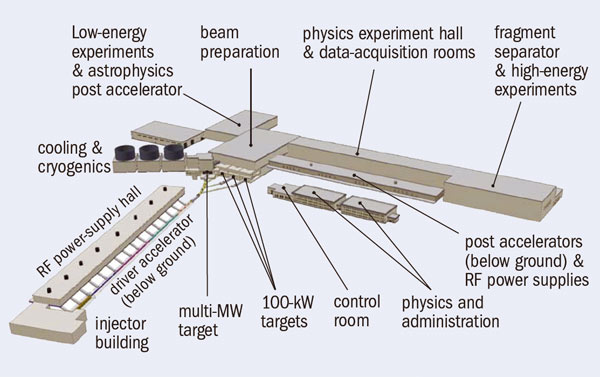
Multiuser capability is an essential ingredient of the EURISOL concept, which is based on a superconducting continuous-wave linac capable of accelerating 5 mA of H– ions to 1 GeV (5 MW beam power). The major part of the beam will be sent to a mercury converter-target where the neutrons produced will induce fission in six uranium-carbide targets surrounding the converter. An innovative magnetic beam-splitting system will create up to three additional 100 kW beams. These will impinge directly on solid targets to induce spallation reactions, which can populate the regions of the nuclear chart that are unattainable in fission reactions. After selection the radioactive beams can either be used at low energies or post accelerated in another superconducting linac with continuous energy variation up to 150 MeV/A for 132Sn, for example. The high-energy neutron-rich beams such as 132Sn, which will reach intensities of up to 1012 particles a second, can then be fragmented to produce high intensities of many otherwise inaccessible neutron-rich nuclei.
“A choice for the location for EURISOL will have to be made in the coming years,” says Blumenfeld, who led the EURISOL design study. “The natural course would be to choose one of the sites of the new ISOL facilities, but a green-field site could also be considered.”
While Europe is on its way towards combining efforts and converging on the EURISOL project, Japan and North America (the US and Canada) are also very active. Speakers from these countries presented their new facilities at EURORIB ’10 and, in some cases, even the first results. Seung-Woo Hong, at Sungkyunkwan University, Korea, for example, is leading the conceptual design project for a heavy-ion accelerator facility for producing RIBs using both the ISOL and the in-flight fragmentation techniques. “This shows that there is a lot of interest for this field all across the world, which is good news for our community,” comments Blumenfeld.
It is clear that nuclear physics is currently a lively field of research. This is easy to understand considering the many links it has with other disciplines and the variety of practical applications, which are becoming increasingly common. “Nuclear physics has a strong and direct link with astrophysics,” says Giovanni La Rana of the Italian National Institute of Nuclear Physics (INFN), describing one example. “Stars live because of nuclear reactions, and to understand how elements are synthesized in the stars scientists need information about nuclei involved in the reactions. Exotic nuclei are involved in the supernovae explosions and to study these processes, one needs masses, cross-sections and lifetimes of these nuclei. So far, the information is extrapolated from stable nuclei through theoretical models, but the new facilities should give us access to these new exotic nuclei.”
By contrast, Alexander Herlert, ISOLDE physics co-ordinator, cites applications closer to Earth. “Researchers implant radioactive nuclei into materials,” he says. “Observing the decay, they can study the properties of the materials. This technique, complementary to other solid-state techniques, allows them to understand the structure of semiconductors and new types of materials.” Nuclear-physics techniques also find application in the medical field, particularly in what is known as isotope harvesting. “Our facilities can produce all sorts of isotopes, basically anything,” says Ulli Köster of the Institut Laue-Langevin, who presented the future perspectives for the field at the conference. “If the doctors need to test new isotopes for medical imaging or treatment, then we can produce them.”
EURORIB ’10 certainly revealed the present vitality in nuclear physics. The talks and discussion sessions underlined the close scientific and technical collaboration between the different RIB facilities, which is propelling the field towards a unified European perspective.
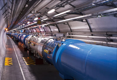
The LHC is probably the largest and most complex scientific instrument ever built. It relies on superconductivity, which plays a fundamental role because it allows magnetic fields in excess of 8 T to be reached. Combined with the radius of curvature of 2.804 km in the dipole (bending) magnets, this field enables proton beams to reach energies of 7 TeV, almost an order of magnitude higher than in previous accelerators. In total there are 1734 large, twin-aperture superconducting magnets, which include the backbone of 1232 main dipoles, each 15 m long. There are also 7724 smaller superconducting corrector magnets. To reach the design performance nearly all of the magnets are cooled with superfluid helium to 1.9 K. The total stored magnetic energy will be about 9000 MJ when running with the dipoles at 8.3 T and a beam energy of 7 TeV.
After 25 years from conception via R&D and construction to commissioning, the LHC started up in spectacular fashion on 10 September 2008. The success of this first commissioning with beam demonstrated the excellent field quality and geometry of the magnets, their precise alignment and good stability, the accuracy of the power supply and the successful operation of the highly complex 1.9 K cryogenic system. Only nine days later, however, in the course of hardware commissioning, a severe incident occurred in sector 3-4 during a ramp of the main dipole current to 9.3 kA (corresponding to a magnetic field of about 6.5 T). It was the final ramp before definitive commissioning of all eight sectors of the machine for operation at 8.6 kA and, hence, an energy of 5 TeV. Many magnets quenched and eventually helium was released into the tunnel and general power was lost in the sector. The incident led to a delay of more than a year before the physics programme began successfully in November 2009.
The first inspection of the LHC tunnel after the incident revealed considerable damage along a zone about 750 m long. There was deformation of connections, electrical faults, perforation of the helium vessel, local destruction of the beam tube with heavy pollution by debris including fragments of multilayer insulation, breakage or damage of cold support posts, breaches in the interconnection bellows, damage to the warm jacks that support the magnets and cracks in the tunnel floor. The pollution of the beam tubes from tiny confetti-like fragments of insulation extended much further, spanning the sector’s full 3 km-long arc. A task force led by Philippe Lebrun was immediately set up to analyse the incident and propose remedies. Within a month, CERN published the first interim report, followed by a more detailed second report in December 2008. The final report was published at the end of March 2009 (Bajko et al. 2009).
It soon became clear that the root of the incident lay with a single fault in an electrical connection between two adjacent magnets, which had led to extensive collateral damage. A defective joint had created a small resistive zone in a superconducting busbar designed to carry a maximum current of 13 kA. It was a small fault in a relatively low-tech system, but it had dramatic consequences, thanks to the subtleties of superconductivity.
Before discussing this in more detail, it is worth describing the magnet powering and the scheme designed to protect the magnets when a quench occurs. In a quench, a conductor rapidly changes from being superconducting (with no resistance) to being normally conducting (resistive). This transition creates a sudden heating effect in the resistive region. This needs to be controlled swiftly to avoid permanent damage to a magnet because the conductor can no longer sustain the high current, and the magnetic energy – about 7 MJ per dipole magnet – is converted into heat.
Busbars and splices
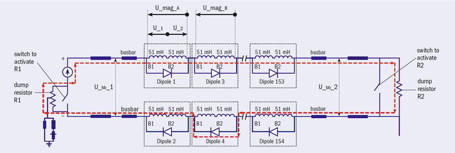
The main magnets of the LHC are connected electrically in a series via 13 kA superconducting busbars in eight main circuits, one per sector. Figure 1 shows a simplified version of the powering and protection scheme for one sector. The 154 dipoles in the sector are powered in series from one 13 kA power convertor – with a dump resistance connected in parallel. The quench-detection system (QDS) monitors for resistive transitions in a magnet by comparing the voltages across the two apertures. When the onset of a quench is detected the system switches in the dump resistor. The inductance, L, of the whole circuit and its resistance, R (determined by the current and maximum voltage), give a 1/e discharge time, L/R, of 104 s, which is far too long for the magnet to survive. Each magnet therefore has a cold bypass-diode and heaters on the coils. As soon as a resistive transition is detected the heaters are fired so as to quench the coils in less than 50 ms. The subsequent sudden rise in voltage turns on the diodes so that they conduct and the current in the quenched coils decays to almost zero in less than 1 s. Meanwhile, all of the unquenched magnets in the sector and the busbars that bypass the quenched coils continue to carry the full current.
The busbars, in which the diodes are inserted, not only bypass any quenched magnet(s) electrically but also serve as a connection between adjacent magnets. So during a magnet quench the busbars carry the overall circuit current, decaying with a time constant of 104 s at the interconnections as well as in the quenched magnet(s). These busbars consist of a superconducting cable that is thermally and electrically coupled to a copper stabilizer along its whole length. The copper cross-section of the stabilizer is designed to be sufficient to carry the current safely, with no damage to the busbar, for the 104-second long discharge even if its superconducting cable is driven into the normal state.
In the case of the incident on 19 September 2008, analysis revealed that a sudden increase of the voltage occurred in the main dipole circuit in sector 3-4, such that the power supply could not deliver the required current. This initiated a fast de-ramp of the magnets, discharging their energy in the dumping system. The discharge was faster than the nominal time constant of 104 s and the circuit quickly became divided into two branches, indicating the presence of a short-circuit. Several magnets quenched.
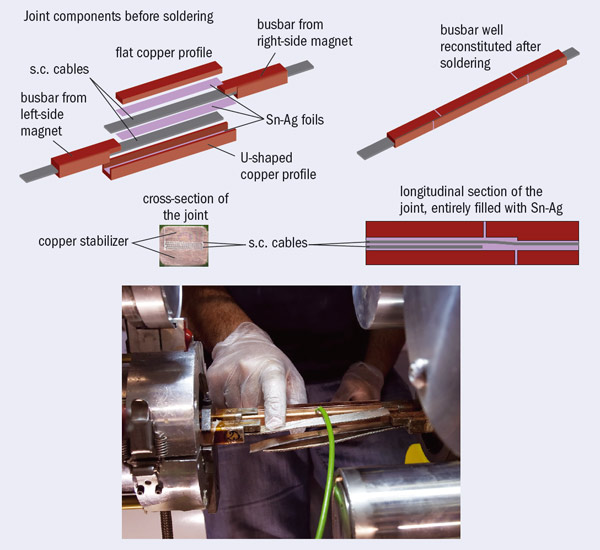
The basic fault appears to have been a defective joint in the 13 kA connection between superconducting cables in two adjacent magnets
The basic fault appears to have been a defective joint in the 13 kA connection between superconducting cables in two adjacent magnets. As figure 2 shows, soft soldering based on tin-silver alloy is used not only to splice the superconducting cable but also to connect the copper stabilizer of the interconnection to both the cable joint and the stabilizing copper of the busbar. When finished, the connection looks like a continuation of the busbars that run along the whole length of the magnet system. The splice between superconducting cables is specified to have a resistance below 0.6 nΩ at 1.9 K. The actual results on samples during production showed an average of 0.2 nΩ with a variance of less than 0.1 nΩ. The resistance of the splice that failed was later evaluated to have been around 220 nΩ.
As they are superconducting, the busbars also have a QDS. This did not intercept the fault, however, because it was not sensitive enough to detect the approximately 2 mV voltage of the resistive zone; the sensitivity was, in fact, 300 mV with an intervention threshold of 1 V. It was subsequently found that, during a current plateau at 7 kA the previous day, sensors on the magnet had indicated a small but distinct increase in temperature of 40 mK above 1.9 K. This was a clear sign of the existence of an abnormal heat dissipation of 10.7 ± 2.1 W, corresponding to a resistance of 180–260 nΩ. (We now know, a posteriori, that we can use this “calorimetric” technique to detect these types of faults.) Had the resistance remained as small as this there would have been no major problem. However, because the current was ramped up to 8.7 kA on 19 September, localized heating increased the resistance, leading to thermal runaway. The heat dissipation was nearly 9 kW by the time the quench-detection threshold of 1 V was reached. Within a second, an electrical arc developed, puncturing the helium enclosure. This led to a release of helium into the insulation vacuum of the cryostat and the subsequent collateral damage described above.
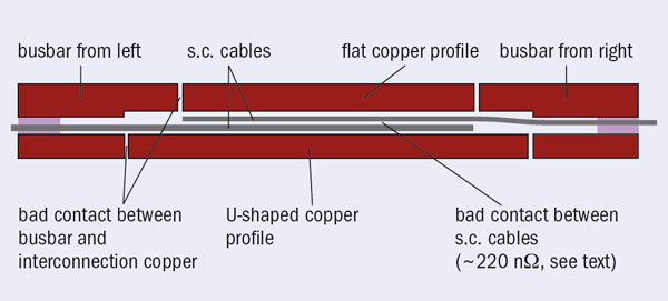
So what had happened? A thermoelectrical model was able to simulate the thermal runaway of the resistive zone in the splice at 8.7 kA, based on the hypothesis of a resistance of 220 nΩ together with a lack of contact between the superconducting cable and copper stabilizer at the joint, as well as the existence of a longitudinal gap in the stabilizer as in figure 3 (Verweij 2009). This discontinuity in the stabilizing copper is important because it impedes the sharing of current between cable and stabilizer. The time constant of the current decay in the busbar is 104 s and the copper there is designed to cope with the heat generated as the current decays in the whole circuit. By contrast, the copper matrix of the superconducting cable is of a size that is sufficient to withstand a discharge time in a resistive state of less than 1 s – the decay time for a single magnet. If there is a discontinuity in the copper stabilizer as well as no contact between the cable and stabilizer, the joint in the superconducting cable cannot sustain the 104 s-long discharge and it melts away.
A subtle enemy
Thus, while the incident was triggered by a bad splice – that is a bad superconductor-to-superconductor joint – the analysis revealed a more subtle possibility. Although the splice between superconducting cables may be good, the surrounding copper stabilizer may not be in contact with the cable, as shown in figure 4. In fact, if the stabilizer is in good contact with the superconducting cable and just has a short longitudinal gap – a few millimetres, say – there is no danger: in a quench of the joint the current can pass through the copper matrix of the superconducting cable and the small amount of heat generated can escape easily via conduction in helium or the busbar.
However, if this gap is coupled with a lack of tin-silver soldering, i.e. the cable at the splice-to-busbar transition is not in good contact with the stabilizing copper for a certain length, then the situation can diverge. The current has to flow through the cable for the whole distance that the cable is isolated and the heat may become too large to escape before a large rise in temperature occurs, initiating thermal runaway and rapidly reaching the melting point in a few seconds. An interconnection joint can be quenched by external heating, for example by warm helium coming from a nearby quenching magnet. The lack of stabilizer continuity could thus cause thermal runaway in the busbar and it turns out to be a more subtle enemy than a bad splice, because it is more difficult to detect.
The task force that investigated the incident proposed a number of remedies, mitigation measures and points to study to improve safety and reliability of the LHC. These included the implementation of a new QDS on the busbars and interconnection line, with a sensitivity threshold of 0.3 mV during a ramp. In a steady state the new QDS can detect a bad splice with a resistance above 1 nΩ. Indeed, the worst interconnection splices have turned out to be about 3 nΩ, far below the runaway threshold, which is estimated to lie well above 50 nΩ.
Moreover, while hunting for bad interconnection splices in October 2008, we realized that the “old” QDS can be used in a measuring mode (rather than the usual active mode) to detect bad splices inside magnets that are in a superconducting state (i.e. at 1.9 K). Although not precise, these (and calorimetric) measurements quickly revealed three magnets (two in the LHC and one in reserve) with defective internal splices of 100, 50 and 25 nΩ. The two installed magnets were replaced, an action that meant that four sectors in total had to be warmed up during the shutdown in 2008–2009. More precise, dedicated tests that were made during the last months with the QDS system in measuring mode found no further bad internal splices, although the system did find 12 dipoles with an internal resistance well above the specification but below 25 nΩ. Internal splices are much less dangerous than interconnection splices because they are covered by the QDS of the magnets, where the current is cut off in less than 1 s. Moreover, all internal splices had been checked during cold-acceptance tests of the magnets at 8.6–9.0 T
The danger of the lack of stabilizer continuity in the busbar required a separate diagnostic method. By measuring a busbar in its resistive state (i.e. warm) over a minimum length (two or three magnets, i.e. 30 or 45 m) one can infer if there is a zone or zones where the cable is not in contact with the stabilizer in conjunction with a gap in the stabilizer. So far this has been done for the four sectors that were warmed up during the long shutdown. In these, all of the bad joints where the defect was longer than 20–25 mm were fixed by resoldering. The other four sectors were measured at 80 K with much less accuracy. As a result one of these sectors was warmed up and three bad joints were repaired, although some defects of almost 40 mm remain, and will be fixed in future.
In the three sectors that were not warmed up, the inherent uncertainty in the cold measurements, means that defects up to 70 mm long have not been excluded. This limits the maximum safe current for powering the magnets with no risk of thermal runaway in the joints. Different studies based on different models have been made to evaluate the critical defect length, based on input from an experiment performed with a cable insulated from the busbar stabilizing copper for 50 mm. The results of these studies led to the decision to limit the field of the magnets to 4.5 T to begin with, and so allow commissioning with collisions at 3.5 TeV per beam, half of the maximum energy (Myers 2010). The LHC has been operating successfully in this manner since the end of March and will continue to do so throughout 2010 and 2011, allowing the experiments to gather significant amounts of data.
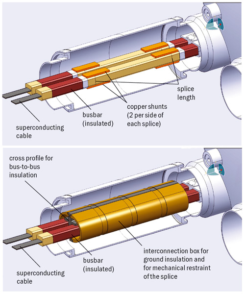
To exploit the full potential of the accelerator by pushing the magnets to 8.3 T, all bad interconnections with the cable detached from the stabilizer copper will have to be fixed. Experience with the sectors that were raised to room temperature during the shutdown suggests that around 10–15% of the joints will need to be resoldered. In addition, we have devised a system that will stabilize all of the interconnections. This involves a relatively simple copper shunt that will be soldered across all of the 10,000 or so interconnections (figure 5). This shunt will definitely cure the issue of the possible lack of continuity of the stabilizer. The aim is to ensure the complete electrical stability of the superconducting magnet system for the LHC’s foreseen lifetime of 25 years (Bertinelli et al. 2010). This will in turn allow the fullest possible returns in terms of new physics in a previously unexplored energy region.
• This article is based on the longer report, Superconductivity: its role, its success and its setbacks in the Large Hadron Collider of CERN (Rossi 2010).
By the end of June the LHC was making good progress towards delivering the first 100 nb–1 of integrated luminosity at an energy of 3.5 TeV per beam. This followed some two weeks devoted to beam commissioning, with the goal of achieving stable collisions at 3.5 TeV with the design intensity of 8 × 10¹¹ protons per bunch. The first days of July saw machine fills for physics with six bunches per beam at this nominal intensity, providing further boosts to the goal of reaching 1 fb–1 before the end of 2011.
The first collisions at 3.5 TeV between bunches at nominal intensity were achieved on 26 May, following earlier tests on ramping the energy with bunches at this intensity. However, to make progress towards further stable running, the accelerator team needed to perform a variety of commissioning studies to establish the appropriate baseline for operating the LHC in these conditions.
These studies involved establishing the optimal reference settings for both ramping the energy and for a “squeeze” to β* of 3.5 m, prior to bringing the beams into collision. (The squeeze reduces the beam size at the interaction points and is described by the parameter β*, which gives the distance from the interaction point to the place where the beam is twice the size.) The settings include the all-important collimator positions, a key part of the machine protection system, and this alone involved 108 setup operations.
The work also involved commissioning the transverse damper – basically, an electrostatic deflector – to subdue instabilities in the nominal bunches as they are ramped to 3.5 TeV.
By 26 June the teams were ready with a new sequence to ramp, squeeze and collapse the separation at the interaction points to bring three bunches per beam at nominal intensity into collision at 3.5 TeV. With a physics run at an instantaneous luminosity of 5 × 1029 cm–2 s–1, the integrated luminosity in the experiments since 30 March already doubled, rising to more than 30 nb–1. A few days later, on 7 July, the machine ran with seven bunches per beam at nominal intensity and achieved a new luminosity record of 1030 cm–2 s–1. This is one more step towards the goal for 2010 of 1032 cm–2 s–1, which will require 800 nominal bunches per beam.
“Physics at the LHC 2010”, which took place at DESY in Hamburg on 7–12 June, was the first large conference to discuss 7 TeV collision data from the LHC. Covering all fields of LHC physics, it attracted 270 participants, among them many young postdocs and students.
On the opening day, Steve Myers, CERN’s director for accelerators and technology, gave an overview of the LHC’s status and the steps required to increase the luminosity. The spokespersons of the four big experiments, Fabiola Gianotti (ATLAS), Guido Tonelli (CMS), Jurgen Schukraft (ALICE) and Andrzej Golutvin (LHCb) summarized the commissioning of their experiments and the progress in understanding the detectors, and also flashed up the first physics results.
The main message from these presentations was that the LHC is progressing well and that the experiments are well prepared. Data-taking is going smoothly, triggers and reconstruction are working well and detectors are rapidly being understood. Data processing on the LHC Computing Grid is also performing as expected.
There was special emphasis at the conference on the operation and performance of detectors and in the afternoon sessions young researchers reported on experiences in all of the experiments. The reports showed that many design performances have already been achieved or are within close reach. One by-product of understanding the detectors is a “detector tomography”, which has been performed using mainly photon conversions; this has allowed several shortcomings of the detector simulations to be identified and removed.
The pay-off for the years of hard work that led to this excellent knowledge of the detectors has been a quick turnaround time for physics results. After only a few weeks of high-energy data-taking at 7 TeV in the centre-of-mass with an integrated luminosity of about 16 nb–1 delivered to each experiment, all four collaborations have rediscovered almost the full Standard Model particle spectrum – except for the top quark, which is just round the corner.
Among the first LHC physics highlights are the observations of W and Z bosons, and of high-pT jets. In several presentations the audience was reminded of how long the community waited for single weak bosons to be produced in the early days of the SppS. Now, dozens of W and Z bosons have already been reported by ATLAS and CMS in different decay channels. However, there is still a long way to go to match the excellent work done in the electroweak sector by the experiments at Fermilab’s Tevatron.
The political support for the LHC in Germany was touched upon on the third day of the conference. In their messages, Georg Schütte, state secretary in the German Ministry for Education and Research, and Bernd Reinert, state secretary for science and research of the state of Hamburg, expressed the keen interest of the funding bodies for further support and exploitation of the LHC.
Looking at the prospects from the scientific point of view, Mike Lamont of CERN sketched the plans for the LHC and emphasized the goal of collecting 1 fb–1 proton-collision data per experiment at 7 TeV before the end of 2011 (plus two heavy-ion runs). With this integrated luminosity, the LHC will already compete with the Tevatron in a number of fields. It would be sensitive to W’ and Z’ bosons with masses up to 1.9 TeV and 1.5 TeV, respectively, and low-mass supersymmetry would also be in reach. However, the Higgs – if this is indeed nature’s choice – will most likely take longer to be discovered.
The last day of the conference was dedicated to overview talks from other fields (astroparticle physics, dark-matter physics) and concluded with an excellent experimental summary by CERN’s Peter Jenni and a visionary overview of theory by David Gross, the 2004 Nobel laureate in physics. Gross reflected on 20 predictions made in 1993 – a good fraction of which have already come true. There is reason to hope that at least a few others (among them the discoveries of the Higgs, supersymmetry and the origin of dark matter, and the transformation of string theory into a real predictive theory) will also come true. There are exciting times ahead.
Over the past 30 years, the Budker Institute of Nuclear Physics in Novosibirsk has developed many free-electron lasers (FELs). The most recent one, which has been in operation since 2003, is a continuous-wave terahertz FEL based on a single-orbit energy-recovery linac (ERL), which is the world’s most intense radiation source at terahertz wavelengths. The laboratory is now making progress in constructing a four-orbit 40 MeV electron ERL to generate radiation in the range 5–250 μm. Already operating with two orbits, this is the world’s first multiturn ERL.
FELs provide coherent radiation in the wavelength range from 0.14 nm to 1 mm. They use the phenomenon of stimulated radiation from relativistic electrons moving in an undulator – a special magnet that creates a periodic alternating field such that the electron trajectory remains close to a straight line (the undulator axis). Travelling through an undulator, electrons amplify a collinear electromagnetic wave if the last one has wavelength λ = d/(2γ2), where d is the undulator period, and γ is the particle’s total energy divided by its mass.
Unfortunately, the maximum electron efficiency of FELs is only about 1%, which makes energy recovery a desirable feature. The simplest realization of energy recovery for an FEL is to install it into a straight section of a storage ring. Such storage-ring FEL facilities exist now but the power of their radiation does not exceed a few watts. The intrinsic limitation of the power is caused by multiple interactions of the same electrons with light, which increases the energy spread of the beam. To achieve high light power, it is better to use a fresh beam, which is just what ERLs can do.
The Novosibirsk ERL has a rather complicated magnetic system, which makes use of a common accelerating structure (figure 1). This differs from other ERL-based FEL facilities in that it uses low-frequency (180 MHz) non-superconducting RF cavities, with continuous-wave operation. The existing terahertz FEL uses one orbit, which lies in the vertical plane. This FEL generates coherent radiation, tunable in the range 120–240 μm. It produces a continuous train of 40–100 ps pulses at a repetition rate of 5.6–22.5 MHz. The maximum average output power is 500 W, with a peak power of more than 1 MW. The minimum measured linewidth is 0.3%, which is close to the Fourier-transform limit. A beamline directs the radiation from the FEL in the accelerator hall to the user hall. It is filled with dry nitrogen and separated from the accelerator vacuum by a diamond window, and from the air by polyethylene windows. Radiation is delivered to six stations, two of which are used for the measurement of radiation parameters, and the other four by users, typically biologists, chemists and physicists.
The other four orbits of the final ERL lie in the horizontal plane. The beam is directed to these orbits by switching on two round magnets. The electrons will pass through the RF cavities four times, to reach 40 MeV. After the fourth orbit the beam will be used in an FEL, before being decelerated four times. A bypass with another FEL is installed at the second orbit (20 MeV). When the bypass magnets are switched on, the beam passes through this FEL. The length of the bypass has been chosen to provide the delay necessary in this case to give deceleration on the third pass through the accelerating cavities.
Two of the four horizontal orbits were assembled and commissioned in 2008. The electron beam was accelerated twice and then decelerated down to the low injection energy, thus successfully demonstrating the world’s first multiorbit ERL operation. The first lasing of the FEL at the bypass was achieved in 2009, providing radiation in the wavelength range 40–80 μm. At first a significant (several per cent) increase in beam loss occurred during lasing. Sextupole correctors were therefore installed in some of quadrupoles to make the 180° bends achromatic to second order. This increased the energy acceptance for the reused electron beam. The output power is about 0.5 kW at an ERL average current of 9 mA. The output of this new FEL is near 70 μm, so the power obtained is also the world record for this wavelength range.
The beamline to deliver radiation from the new FEL to existing user stations has been assembled and commissioned. Thus, the world’s first two-orbit ERL is now operating for a far infrared FEL. In the meantime, the assembly of the third and fourth ERL orbits is in progress.
The physics potential for QCD experiments with high-energy polarized antiprotons is enormous but until now many experiments have been impossible owing to the lack of a high-luminosity beam. This situation could change with the advent of a stored beam of polarized antiprotons and the realization of a double-polarized, high-luminosity antiproton–proton collider. The collaboration for Polarized Antiproton Experiments (PAX) has already formulated the physics programme that would be possible with such a facility (PAX collaboration 2006). Following studies with proton beams, it is now planning to make the first measurements with polarized beams at CERN’s Antiproton Decelerator (AD), which is currently the world’s only stand-alone antiproton storage facility.
The experimental approach adopted by the PAX collaboration to produce a beam of polarized antiprotons is based on spin filtering, a technique that exploits the spin dependence of the strong interaction (Oellers et al. 2009). The total cross-section, σ, depends on the relative orientation of the spins of the colliding particles, i.e. σ(↑↑)≠σ(↑↓). The method was shown to work in the 1990s with protons in a 23 MeV beam stored in the Heidelberg Test Storage Ring, which passed through a polarized hydrogen gas target (Rathmann et al. 1993).
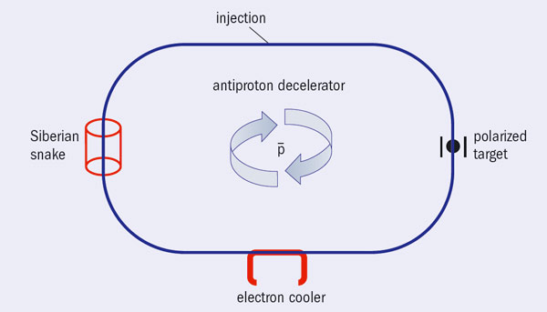
In contrast to the proton–proton system, the experimental basis for predicting the build-up of polarization in a stored antiproton beam by spin filtering is practically nonexistent. It is therefore a high priority to perform a series of dedicated spin-filtering experiments using stored antiprotons together with a polarized target, which the PAX collaboration is aiming to undertake at the AD ring at CERN (PAX collaboration 2009b). Figure 1 illustrates schematically the proposed experimental set-up.
Expected build-up
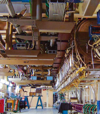
The AD is a unique facility at which stored antiprotons in the appropriate energy range are available with characteristics that meet the requirements for the first antiproton polarization build-up studies. In 2009, the European Research Council awarded an Advanced Grant to the Jülich group to pursue these studies at the AD. Once an experimental proton–antiproton data base is available, work can begin to design a dedicated polarized antiproton ring.
The Jülich group has made predictions for the spin-dependent cross-sections for the expected build-up of polarization in an antiproton beam (PAX collaboration 2009). In addition, a group from the Budker Institute for Nuclear Physics, Novosibirsk, has recently generated estimates on the basis of a Nijmegen proton–antiproton potential. These indicate that antiproton beam polarizations of 0.15–0.20 (spin filtering with transverse target orientation) and 0.35–0.40 (longitudinal) might be expected (Dmitriev et al. 2010).
For efficient commissioning of the equipment required for measurements at the AD, the PAX collaboration is preparing polarization build-up studies using stored protons at the Cooler Synchrotron (COSY) at Jülich (PAX collaboration 2009a). Because the spin-dependence of the proton–proton interaction is well known at energies where electron cooling is available at COSY (up to 130 MeV), details of the polarization build-up process can also be studied.
Beautiful techniques
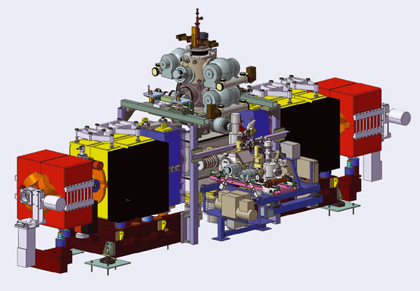
The polarized internal target (figure 2), consisting of an atomic beam source and a Breit-Rabi type target polarimeter, has been successfully operated with an openable storage cell. Such an openable cell constitutes an important development for the investigations with stored antiprotons at the AD: when the beam is injected into the AD with a momentum of around 3.5 GeV/c, any restriction of the machine acceptance reduces the number of stored antiprotons during the spin-filtering studies. Only after cooling and deceleration to the experimental energies of interest, around 50–500 MeV, would the storage cell be closed.
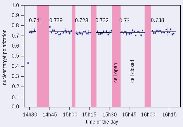
The storage-cell technique works beautifully, as figure 3 shows, with the target polarization unaffected by the opening and closing of the storage cell (Barschel 2010). This constitutes a major milestone because for the first time, both high polarization and density have been achieved with an openable storage cell. While this is crucial for investigations of the spin-dependence of the proton–antiproton interaction at the AD, many other experiments employing internal storage-cell targets can also benefit from this development.
The quadrupole magnets for the low-β insertion of PAX at COSY were installed during the summer shutdown in 2009. During beam-time in early 2010, the β-functions at the location of the PAX quadrupoles were measured for the non-zero dispersion setting, by varying the magnet currents. The calculated and measured values at the location of the quadrupoles match nicely, as figure 4 shows. The model calculations suggest that β-functions of βx around 0.38 m and βy around 0.36 m were reached. The measured beam lifetimes at COSY did not depend on whether the low-β section was powered on or not. More accurate values of βx and βy at the centre of the storage cell will be determined once the target chamber has been installed later this year.
In the second half of 2010, the PAX collaboration would like to perform machine studies at COSY to obtain a better insight into the actual limitations of the beam lifetime. The plan is then to carry out the first spin-filtering measurements at COSY with transversely polarized protons early in 2011.
The installation at the AD will consist of a set of additional quadrupole magnets, the internal target and a detection system surrounding the openable storage cell (figure 5). The PAX proposal for the AD is currently awaiting approval (PAX collaboration 2009b). It would be advantageous if the six additional quadrupole magnets could be installed without modification of the current AD lattice (i.e. while the central AD quadrupole magnet in that section remains in place). Subsequent machine studies to commission the low-beta section would ensure that the proposed experimental set-up for the spin-filtering studies is compatible with the other physics pursued at the AD. Once satisfactory operation of the equipment has been achieved, the first measurements of the polarization build-up in proton–antiproton scattering will be possible. A Siberian snake needs to be installed at a later stage, as figure 1 indicates, and the AD electron cooler upgraded to provide cooled antiproton beams with an energy of up to 500 MeV.
The weeks following the first collisions at 7 TeV in the centre of mass have seen the LHC pass important milestones in delivering higher instantaneous luminosity to the experiments. With days dedicated mainly to beam-commissioning studies and nights given over to the preparation and delivery of collisions for experiments, the progress is clear to see.
The weekend of 23–24 April saw not only a tenfold increase in instantaneous luminosity to above 1.1 × 1028 cm–2 s–1 in all four experiments but also a record physics fill, with the machine in “stable-beam” mode for 30 hours. This allowed the experiments to more than double the total number of events recorded at 7 TeV. The successful weekend had been preceded by work to commission the “squeeze” on the beams at an energy of 3.5 TeV per beam at all four interaction points. This process, one of the most complex stages in the operation of the accelerator, was followed by a number of collimation and beam-dump tests to ensure sufficient protection of the experiments. The first physics fill with squeezed-beam optics led to a factor of five improvement in luminosity. A new bunch scheme with three bunches per beam then provided a further improvement by another factor of two.
Sunday 2 May saw another major step towards higher intensities with the first fill with two bunches per beam at the nominal (design) intensity of 1 × 10¹¹ protons per bunch, at the injection energy of 450 GeV per beam. Within an hour of injection the team had removed the “separation bumps”, which keep the beams separated during the ramp, at all four interaction points simultaneously, thus providing collisions. After some further adjustments the operators were ready to prepare a second fill, this time with collisions in stable beam conditions, for the first time with bunches at nominal intensity.
The following two weeks saw further steps in a two-pronged approach to deliver higher luminosity to the experiments, either with more bunches or more protons per bunch. With two bunches per beam providing a total of up to 4 × 10¹⁰ protons per beam, the LHC was already delivering an instantaneous luminosity of 2 × 1028 cm–2 s–1 in some long periods of stable running at 3.5 TeV per beam on the weekend of 8–9 May.
After further tests, on the beam-dump system and aspects of machine protection, for example, on 14 May, a physics fill began with squeezed beams and four bunches per beam, giving a total of 8 × 10¹⁰ protons per beam. The next day, the first test took place to ramp a beam at nominal intensity at 3.5 TeV, with 60% of the beam surviving the ramp. This was followed by a long fill of stable beams for nearly 24 hours, now with six bunches per beam. It was then time to try ramping again with one bunch at nominal intensity and this eventually succeeded for beam 2, with 1.2 × 10¹¹ protons, in fact, 10% above nominal and without losses.
By the end of the long weekend of 14–16 May, the LHC had doubled the integrated luminosity previously delivered since the restart in March. Then, on the evening of 17 May, both beams were successfully ramped at nominal intensity, marking the passage of another milestone in the progress towards the final targets for the year.
Twenty years ago, an amateur scuba diver swimming off the coast of Oristano in Sardinia found a navis oneraria magna – a 36-m Roman ship dating back more than 2000 years, to between 80 and 50 BC – whose cargo consisted of a 1000 lead forms. These were recovered with help from Italy’s National Institute of Nuclear Physics (INFN), which at the time received 150 of the lead bricks. Now, INFN is to receive a further 120 bricks to complete the shielding for the Cryogenic Underground Observatory for Rare Events (CUORE), in INFN’s Gran Sasso National Laboratory (LNGS).
INFN has received the lead bricks from the National Archaeological Museum of Cagliari in Sardinia. The bricks, together with the ship that transported them, had remained in the sea for two millennia, during which time the albeit low original radioactivity of one of the radionuclides, 210Pb, decreased by approximately 100,000 times. The 210Pb, which has a half-life of 22 years, has by now practically disappeared from the ancient Roman lead.
The parts of the bricks that contain inscriptions will be removed and conserved, whereas the remainder will be cleaned of incrustations and melted to construct a shield for the international CUORE experiment. Moreover, researchers from INFN will perform precise measurements on the lead (and possibly on the copper that was also found on the ship) to study the materials used in the Bronze Age.
The lead bricks were made available as the result of a collaboration involving INFN, its facilities in Cagliari and the Archaeological Superintendency of Cagliari, as well as with the support of the General Directorate of Antiquity. As part of this joint operation 20 years ago the INFN contributed 300 million lira for the excavation of the ship and the recovery of its cargo.
The bricks, which weigh about 33 kg each and are 46 cm long and 9 cm wide, will be used to shield the CUORE experiment. This collaboration is seeking to discover the extremely rare process of neutrinoless double-beta decay, which would allow researchers not only to measure directly the mass of neutrinos but also to determine whether or not they are Majorana particles (i.e. particles and antiparticles are one and the same). The detector will be based on an array of nearly 1000 tellurium-dioxide bolometers, cooled to about 10 mK.
A meeting at GSI Darmstadt on 8–10 April provided a first opportunity to formulate a strategy on the laser technology needed to meet the challenge of future accelerators that will use or rely on lasers with very high average power. Hartmut Eickhoff, technical director of GSI, and Wim Leemans of Lawrence Berkeley National Laboratory opened the event. Leemans is chairman of the newly established Joint Task Force on Future Applications of Laser Acceleration, which operates under the umbrella of the International Committee for Future Accelerators (ICFA) and the International Committee on Ultra-High Intensity Lasers (ICUIL). The task force had invited experts on high-power laser technology and accelerator technology and their applications to this first meeting. Altogether, there were 47 participants from countries around the world, including China (1), France (4), Germany (18), Japan (4), Switzerland (2), the UK (4) and the US (14).
The main topics of discussion were the laser performance needed for accelerator technology to support the most challenging present and future needs, as well as questions of laser architecture, laser material and optical components. Representatives from accelerators and light sources outlined the top-level laser requirements for potential laser-based accelerator applications – that is, for colliders, light sources and medical applications.
The biggest challenge for laser technology is a laser-plasma e+e– collider with the goal of a top energy of 10 TeV. The consensus in the global high-energy physics community is that the next large collider after the LHC should be a tera-electron-volt-scale lepton collider. Options currently under study include an International Linear Collider (ILC) at 0.5–1 TeV, a Compact Linear Collider (CLIC) at up to 3 TeV and a muon collider at up to 4 TeV, all using RF technology. On the other hand, the very high gradients of around 10 GeV/m that are possible with laser acceleration, offer new avenues to reach even higher energy and more compact machines.
The workshop investigated the beam and laser parameters of a 1–10 TeV e+e– collider, with a luminosity of 1036 cm–2s–1, based on two different technologies – laser plasma acceleration and direct laser acceleration. The main challenges to the practical achievement of laser acceleration are high average power (around 100 MW), high repetition rate (kilohertz to megahertz), and high efficiency (around 40–60%) at a cost that ideally would be an order of magnitude lower than using technology based on RF. The workshop also studied the laser requirements for a 200 GeV γγ collider, proposed as the first stage of a full-scale ILC or CLIC. The laser systems required for such a collider may be within reach of today’s technology.
For light sources, lasers already play a significant role in existing facilities but they face new challenges with future projects that aim at much higher repetition frequencies. Ultrafast (femtosecond) lasers reaching levels of 1–10 kW will be required for use as “seed lasers” and for user-driven experiments. The third area of application is the use in medicine of laser acceleration of protons or ions and its potential to replace technology currently used in tumour therapy. Such lasers typically have very high peak-power (petawatt class) and require special pulse shapes with very high temporal contrast. Again, compact multi-kilowatt lasers will be needed.
Laser requirements for these applications are often many orders of magnitude beyond the capabilities of the lasers that are used in today’s scientific work, i.e. they require megawatts instead of tens of watts. Representatives from laser science at the meeting discussed and outlined how, with appropriate R&D, emerging 100-kW-class industrial lasers, 10-MW-class laser technologies for fusion energy and megawatt-class laser systems for defence work might be adapted to meet these challenging requirements.
Results from the workshop, including tables of the parameters required for laser technology and the goals, will be compiled in a report and submitted to ICFA and ICUIL for their approval, prior to public release.
To provide the best experiences, we use technologies like cookies to store and/or access device information. Consenting to these technologies will allow us to process data such as browsing behavior or unique IDs on this site. Not consenting or withdrawing consent, may adversely affect certain features and functions.
Functional
Always active
The technical storage or access is strictly necessary for the legitimate purpose of enabling the use of a specific service explicitly requested by the subscriber or user, or for the sole purpose of carrying out the transmission of a communication over an electronic communications network.
Preferences
The technical storage or access is necessary for the legitimate purpose of storing preferences that are not requested by the subscriber or user.
Statistics
The technical storage or access that is used exclusively for statistical purposes.The technical storage or access that is used exclusively for anonymous statistical purposes. Without a subpoena, voluntary compliance on the part of your Internet Service Provider, or additional records from a third party, information stored or retrieved for this purpose alone cannot usually be used to identify you.
Marketing
The technical storage or access is required to create user profiles to send advertising, or to track the user on a website or across several websites for similar marketing purposes.