Comsol -leaderboard other pages

Topics

Mission accomplished: a new hall for PETRA III

With a handover ceremony at the end of June, an exciting year of hard work on DESY’s new synchrotron radiation source, PETRA III, came to a successful conclusion for the construction team of general contractor Ed. ZÜBLIN and the DESY project team. They had completed the experimental hall within a year, exactly on schedule. As early as 7 April, DESY was able to take responsibility for the concrete slab on which the new part of the storage ring tunnel and the experiments are being set up. This latest project is the third reincarnation for the PETRA storage ring, which began life as a leading electron–positron collider in the 1980s and later became a pre-accelerator for HERA, the proton–electron collider. It will provide researchers at DESY with one of the most brilliant X-ray sources in the world.
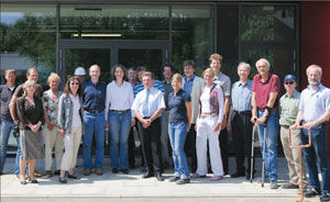
CCpet1_09_08

The PETRA III project comprises the reconstruction of the PETRA accelerator to form a dedicated third-generation synchrotron radiation source together with 14 independent beamlines serving up to 30 experimental stations. An eighth of the ring (288 m long) has been completely remodelled within a new hall that also houses the experiments, and the remainder of the ring (some 2 km) has been completely refurbished. The overall budget of the project was €225 million, shared between the German Federal Government (90%) and the City of Hamburg (10%).

High brilliance guaranteed

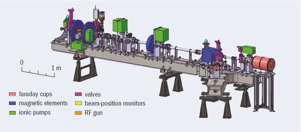
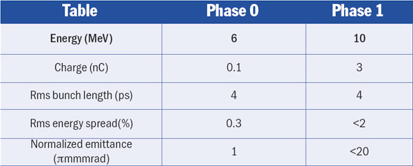
PETRA III will have the lowest emittance – 1 nm rad – of all the high-energy (6 GeV) storage rings in the world. This will be achieved by installing 80 m of damping wigglers in two of the long straight parts of the ring. The high brilliance will be assured by undulators, where periodic magnetic fields force the beam to oscillate and emit intense radiation in a narrow energy band. To free space for the undulators in the new arc, the classic FODO lattice (the basic combination of quadrupole and dipole magnets) has been replaced by a Chasman-Green lattice, which is better optimized for light sources. There the magnets are mounted on girders carrying either two quadrupoles and one dipole, or three quadrupoles.

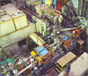
The project officially started in 2004 with the publication of the Technical Design Report (TDR). In the following years an increasing number of DESY staff worked on the detailed planning and preconstruction of accelerator and beamline components, and preparations for the construction activities on the DESY campus finally started in May 2007. However, disassembly of the old accelerator and preparation of the construction site could not start until 2 July 2007, after the last electrons and protons had been delivered to HERA. All the accelerator components had to be removed from the tunnel, an operation that was achieved in only three months. The magnets were refurbished, most of them receiving new coils, and magnetically characterized. They were then mounted again together with the new vacuum system, and in May 2008 the last dipole was installed in its old position. As the plan is for PETRA III to operate in top-up mode, where the storage ring current is kept almost constant with frequent injections of beam, the pre-accelerators and part of the general infrastructure also had to be refurbished.

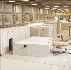
The old PETRA tunnel had to be completely removed in the arc where the new experimental hall was being built. In designing the new hall, extreme care was taken to ensure optimum stability, both for the storage ring and the future X-ray beamlines. The hall floor is cast as a monolithic 1 m thick concrete slab that will support all the components. This slab is mechanically isolated from its surroundings by soft vibration-damping material, and the framework of the hall is built on sleeved piles to minimize the influence it could exert through the ground on the floor of the hall.

CCpet2_09_08

The optimum design of the sleeved piles had to be tested by producing four prototype piles – in effect, the first experiment at PETRA III. Using bubble-wrap foil to sleeve the piles proved to be the most economic and efficient solution. Then for two months, a long procession of trucks removed the sand covering the old tunnel in the section where the new experimental hall was to be built before the remaining 95 piles could be lowered 20 m deep into the ground. At the same time, the 1 m-thick layer of recycled concrete material was brought into place and carefully densified (i.e. hardened). The layer forms the subsoil for the concrete slab. This period of construction ended with the foundation-stone ceremony on 14 September 2007.

It took only two months to erect the hall. By November 2007 the roof was closed and the teams celebrated with a topping-out ceremony attended by German research minister, Annette Schavan. The most exciting task followed in mid-December: the casting of the 1 m-thick base slab. Within 60 hours, 38 trucks brought 860 loads of concrete (some 6700 m3) to the DESY campus where it was pumped into the hall. Half of the concrete (i.e. the upper half of the plate) is reinforced by steel fibres to minimize the number of cracks. The crucial part was the setting of what is possibly the longest single piece of concrete ever cast. During cool-down it performed exactly as predicted, shrinking by 8.2 cm and forming only one crack, which was cured by injecting epoxy resin. Preliminary measurements of the vibration and deformation properties gave promising results. In quiet periods the rms value of the vibrational amplitude at frequencies of above 1 Hz is as low as 20 nm. Finally, by 30 June 2008 work on the façade and the interior of the laboratories and evaluation rooms had finished on schedule.

Meanwhile, the first DESY groups have begun work inside the hall. All the points for the determination of the eventual beam position have been marked along the particle and X-ray beamlines. The laying of the cooling water pipes has started, and shielding stones for the tunnel have been set up inside the hall. Installation of the optics enclosures for the beamlines began in mid-July, and the erection of lead hutches to accommodate the experiments started at the beginning of August.

Experiments, which are organized in nine sectors, have been selected by an international advisory board based on the proposals collected in the TDR. All make use of the high brilliance of the PETRA III beam. Sector 1 will be dedicated to inelastic scattering of a few milli-electron-volts and nuclear resonant scattering with an energy resolution of nano-electron-volts, offering simultaneously a spatial resolution in the few or even submicron range. Sector 2 will be shared by a hard X-ray beamline, with one fixed energy end-station for powder diffraction and one for extreme conditions experiments, and one beamline for micro- and nano-small angle X-ray scattering applications. Sector 3 will house a variable polarization soft X-ray beamline equipped with an Apple-II type undulator and a selection of dedicated end-stations. Sector 4 is the imaging sector with one beamline for tomography (operated by the GKSS Research Centre, Geesthacht) and a hard X-ray nanoprobe beamline dedicated to spatially resolved absorption spectroscopy and fluorescence analysis.

In sector 5 GKSS and DESY will jointly operate a beamline for very hard X-rays (above 50 keV), dedicated mainly to applications in materials science. Sector 6 focuses on diffraction experiments with a very-high-resolution diffraction and a resonant scattering end-station. In addition, a station for electron spectroscopy will be included. Sector 7 makes special use of the high brilliance of PETRA III to perform experiments using the coherent flux. Both X-ray photon correlation spectroscopy and coherent imaging experiments are foreseen. The last two sectors, 8 and 9, are dedicated to applications in life science, with four beamlines operated together with the Max Planck society, the Helmholtz Centre for Infection Research and, with the largest part of three experiments, the European Molecular Biology Laboratory. These beamlines will offer small angle scattering, macro-molecular crystallography and bio-imaging end-stations.

The schedule dictates that the technical commissioning of the machine will start in October, with the first beam expected at the beginning of 2009. During the commissioning of the beamlines, scheduled for spring and summer 2009, DESY will invite already “friendly” users to participate in the characterization of the experiments at this exciting new facility.

CLIC here for the future

CERN’s latest and foremost accelerator, the LHC, is set to provide a rich programme of physics at a new high-energy frontier over the coming years. From 2008 onwards, the LHC will probe the new “terascale” energy region. It should above all confirm or refute the existence of the Higgs boson of the Standard Model and will explore the possibilities for physics beyond the Standard Model, such as supersymmetry, extra dimensions and new gauge bosons. The discovery potential is huge and will set the direction for possible future high-energy colliders. Nevertheless, particle physicists worldwide have reached a consensus that the results from the LHC will need to be complemented by experiments at an electron–positron collider operating in the tera-electron-volt energy range.

The highest centre-of-mass energy in electron–positron collisions so far – 209 GeV – was reached at LEP at CERN. In a circular collider, such as LEP, the circulating particles emit synchrotron radiation, and the energy lost in this way needs to be replaced by a powerful RF acceleration system. In LEP, for example, each beam lost about 3% of its energy on each turn. The biggest superconducting RF system built so far, which provided a total of 3640 MV per revolution, was just enough to keep the beam in LEP at its nominal energy. Moreover, the energy loss by synchrotron radiation increases with the fourth power of the energy of the circulating beam. So it is clear that a storage ring is not an option for an electron–positron collider operating at an energy significantly above that of LEP, as the amount of RF power required to keep the beam circulating becomes prohibitive.

CCcli1_09_08

Linear colliders are therefore the only option for realizing electron–positron collisions at tera-electron-volt energies. The basic principle here is simple: two linear accelerators face each other, one accelerating electrons, the other positrons, so that the two beams of particles can collide head on. This scheme has certain inherent features that strongly influence the design. First, the linacs have to accelerate the particles in one single pass. This requires high electric fields for acceleration, so as to keep the length of the collider within reasonable limits; such high fields can be achieved only in pulsed operation. Secondly, after acceleration, the two beams collide only once. In a circular machine the counter-rotating beams collide with a high repetition frequency, in the case of LEP at 44 kHz. A linear collider by contrast would have a repetition frequency of typically 5–100 Hz. This means that the luminosity necessary for the particle physics experiments can be reached only with very small beam dimensions at the interaction point and with the highest possible bunch charge. As luminosity is proportional to beam power, the overall wall-plug to acceleration efficiency is of paramount importance.

Global collaborations are currently developing two different technologies for linear colliders, each with different energy reach. The International Linear Collider (ILC) collaboration is studying a machine with a centre-of-mass energy of 500 GeV and a possible future upgrade to 1 TeV. This study is based on an RF system using superconducting cavities for acceleration, with a nominal accelerating field of 31.5 MV/m and a total length of 31 km for a colliding-beam energy of 500 GeV. The Compact Linear Collider (CLIC) study is aiming at a nominal energy of 3 TeV, and foresees building CLIC in stages, starting at the lowest energy required by the physics, with successive energy upgrades. The CLIC scheme is based on normal conducting travelling-wave accelerating structures, operating at very high electric fields of 100 MV/m to keep the total length to about 48 km for a colliding-beam energy of 3 TeV. Such high fields require high peak power and hence a novel power source – an innovative two-beam system, in which a drive beam supplies energy to the main accelerating beam. Initiated at CERN, CLIC is now a joint effort by a collaboration of 26 institutes. Although the acceleration technologies for ILC and CLIC are quite different, the two studies share many R&D issues and have developed a solid collaboration on these topics.

The linac design for CLIC is based on travelling-wave accelerating structures operating at a frequency of 12 GHz. These structures are one of the most challenging items being developed for CLIC. They have to be able to withstand the very high accelerating fields of 100 MV/m in pulses 239 ns long without being damaged by unavoidable RF breakdowns and pulsed RF heating. The image below shows the best accelerating structure produced so far. It has been tested to fields of more than 100 MV/m at nominal pulse length and with an extremely low probability of RF breakdown of less than one in 107 pulses.

CCcli2_09_08

The peak RF power required to reach the electric fields of 100 MV/m amounts to about 275 MW per active metre of accelerating structure. With an active accelerator length for both linacs of 30 km out of the 48 km total length of CLIC, the use of individual RF power sources, such as klystrons, to provide such a high peak power is not really possible. Instead, the key innovative idea underlying CLIC is a two-beam scheme to produce and distribute the high peak RF-power. In this system, two beams run parallel to each other: the main beam, to be accelerated, and the drive beam to provide the RF power for the accelerating structures.

Providing the power

The drive beam is a high-current (100 A peak), low-energy (2.38 GeV) beam with a bunch repetition frequency of 12 GHz. It must contain all the energy required to accelerate the main beam, but how does it get this energy? In fact, the drive beam begins life as a long train of electron bunches (139 μs long) with large bunch spacing (60 cm). This is accelerated to an energy of 2.38 GeV using conventional klystron amplifiers at 1 GHz in a normal conducting linac. This acceleration can be made energy efficient, using the so-called fully-loaded acceleration mode, where a transfer efficiency from the RF to the beam of more than 95% has already been demonstrated in the CLIC test facility.

CCcli3_09_08

At this stage the drive beam contains all the energy necessary to accelerate one pulse of the main beam but with a beam current of 4.2 A. In order to get the high peak RF-power necessary for the main beam accelerating structures, the peak current of the drive beam has to be increased to 100 A. This occurs through bunch manipulations in a sequence of three rings that follow the linac: the delay loop and two combiner rings. Here, in one of the important novel features of CLIC, the bunches in 239 ns long sub-trains are interleaved between each other by injection using RF deflectors. This leads finally to bunches spaced by 2.5 cm (12 GHz) in bursts 239 ns long, with an average current during the burst of 100 A. In total, 24 such bursts follow each other, with 5.8 μs intervals between bursts.

The tunnel for CLIC will contain the elements for both the main beam and the drive beam running parallel to each other about 65 cm apart. Transfer lines to transport both beams from the injectors to the far ends of the two linacs can be installed in the same tunnel, under the ceiling.

CCcli4_09_08

To transfer the energy to the main beam, the drive beam passes through novel “power extraction and transfer structures” (PETS), where it excites strong electromagnetic oscillations, i.e. the beam loses its kinetic energy to electromagnetic energy. This RF energy is extracted from the PETS and sent via waveguides to the accelerating structures in the parallel main beam. The PETS are travelling-wave structures like the accelerating structures for the main beam, but with different parameters. One PETS with a different design has already been producing 30 GHz RF power in the CLIC test facility for three years.

CCcli5_09_08

A further challenge for CLIC, in common with the ILC, is to achieve the luminosity that the experiments demand. This requires beams of extremely small emittance. At CLIC, two damping rings in succession will provide the necessary reduction in each of the main beams. In the main linac itself, the RF accelerating structures have been carefully designed to control the wake fields induced by the bunches to avoid blow-up of the emittance. Finally, a sophisticated beam-delivery system focuses the beam down to dimensions of 1 nm rms size in the vertical plane and 40 nm horizontally. This requires the final focus quadrupoles to be stabilized to a vibration amplitude of less than 0.2 nm for oscillations above 4 Hz.

An important milestone will be the proof-of-principle demonstration that the major CLIC technologies are feasible. The CLIC Test Facility (CTF3), currently under construction, should demonstrate the main CLIC-specific issues by 2010.

CTF3 consists of a 150 MeV electron linac, followed by a series of two rings, the delay loop and the combiner ring. This part of CTF3 is a scaled-down version of the complex required to generate the CLIC drive beam. It will demonstrate the principle of the novel bunch-interleaving technique using RF deflectors to produce the compressed drive-beam pulses. In CTF3 the compressed beam is then sent into the CLIC Experimental Hall (CLEX). This houses several beam lines where the CLIC acceleration scheme will be tested, including the extraction of RF power from the drive beam and transfer of this RF power to the accelerating structure, which will accelerate a “probe beam” in a full demonstration of the CLIC acceleration principle.

CCcli6_09_08

Construction of CTF3 started after the closure of LEP in 2001, taking advantage of equipment from LEP’s pre-injector complex. Its installation is on schedule: the linac, delay loop and combiner ring have already been operated with beam, and further commissioning is on going. The new CLEX building is now ready, with most of the equipment installed, and it should see beam from August 2008 onwards.

CCcli7_09_08

The first major milestone towards CLIC will be in 2010 when the most important new technologies should be shown to be feasible, so that a conceptual design report can be published. A technical design phase will follow, including industrialization and cost optimization. Pending a decision based on physics results from the LHC, construction, which is estimated to last seven years from the moment of project approval, could then begin.

CCcli8_09_08

• The R&D work towards CLIC is done by an international collaboration organized like those for the large particle physics experiments at CERN. It is managed by a collaboration board with representatives from the collaborating institutes, each one responsible for work packages and providing the necessary resources. The collaboration currently consists of 26 members from 14 countries: Ankara University Group (Ankara and Gazi), Budker Institute of Nuclear Physics (BINP), CEA (IRFU Saclay), CERN, CNRS IN3P3 (LAL, LAPP, LURE), DAE India (RRCAT), DOE USA (Northwestern University, Illinois, SLAC, JLAB), Helsinki Institute of Physics (HIP), IAP Nizhny Novgorod, INFN Frascati, JINR Dubna, MEC Spain (CIEMAT Madrid, IFIC Valencia, UPC Barcelona), NCP Pakistan, Norwegian Research Council (Oslo University), PSI Switzerland, STFC UK (John Adams Institute, Royal Holloway London), Ukraine Nat. Acad. Sci (IAP NASU), Uppsala University.

THE NEXT CLIC WORKSHOP

The CLIC ’08 workshop will be held at CERN on 14–17 October 2008. It is an accelerator and physics workshop, which provides a forum for those already participating in CLIC, those who are interested in joining, and any others interested in the physics and technology of CLIC. It follows the successful first workshop of this kind held in October 2007.

CLIC ’08 will cover:

* The R&D towards CLIC feasibility demonstration and conceptual design in 2010. This includes items of ILC–CLIC common interest.

* Reflections on the R&D, facilities and engineering efforts needed in the period after 2010 to progress from a conceptual design to a technical design.

* Particle physics and detector issues of a multi-TeV linear collider.

* More information about CLIC ’08 is available at http://project-clic08-workshop.web.cern.ch/.

Polarization brings to light the accretion discs inside quasars

The extreme luminosity of quasars is thought to be generated by supermassive black holes accreting surrounding material at the heart of galaxies. If the accretion has a preferred rotation axis, the infalling gas and dust should eventually form an accretion disc round the black hole. An accretion disc is far too small for such distant objects to be seen in an image, but even its expected spectral characteristics have hitherto not been identified. A new study can now disentangle accretion-disc emission from that of dust, using infrared polarization measurements.

Quasars are the most luminous persistent sources of radiation in the universe. They radiate about 1000 times as much energy as all of the stars in their host galaxy. Such extreme luminosities can be achieved by the accretion of matter by a supermassive black hole. Gravitational accretion is indeed much more effective in radiating energy – typically about 10% of the accreted mass-energy – than the modest 0.7% yields of hydrogen fusion in stars. The accretion could be chaotic with no preferred direction, but the presence of jets stretching over millions of light-years in some quasars indicates a preferred direction, defined by the spin axis of the black hole and/or the rotation axis of an accretion disc (CERN Courier July/August 2006 p10).

Nikolay Shakura and Rashid Sunyaev derived the expected emission from an optically thick accretion disc back in 1973. The temperature gradient from the hot inner disc regions to the cooler external parts is expected to emit a spectrum characterized by a spectral index of +1/3 (Fν ∝ ν+1/3), whereas the optical-ultraviolet spectra of quasars have an observed slope in the –0.2 and –1.0 range. This excess of emission in the red part of quasar spectra remained a puzzle for 35 years. Although it was usually ascribed to additional dust emission, it prevented astronomers from finding evidence for the accretion-disc origin of the dominant optical-ultraviolet emission of quasars.

An international team of astronomers led by Makoto Kishimoto from the Max-Planck-Institut für Radioastronomie in Bonn and the Royal Observatory of the University of Edinburgh, has now found the characteristic spectral signature of an accretion disc in six quasars. It discovered a spectral slope consistent with the expected +1/3 index in the polarized near-infrared emission of these quasars. The team argues that the emission of the accretion-disc is revealed in polarized light because it is scattered by free electrons in the near vicinity of the black hole, whereas the emission of surrounding dust clouds is not scattered and thus not polarized. The infrared polarization observations have been made with the infrared polarimeter mounted on the UK Infrared Telescope on Mauna Kea in Hawaii.

These results provide evidence that the controversial accretion disc is truly there in quasars and has the expected properties in its outer regions where the observed infrared emission is thought to originate. The optical-ultraviolet emission from the inner regions of the disc closer to the black hole is, however, not yet well understood.

Cryogenic jets defy Rayleigh’s theory

Many technical and scientific applications, such as experiments with internal targets at particle accelerators, require the transport into an interaction zone of substances that are gaseous at room temperatures. At the same time, the pressure in the surrounding vacuum chamber must be kept as low as possible. One solution to this technological challenge are the so-called frozen-pellet targets, which provide fluxes of solid pellets produced from H2, N2, Ar or Xe, for example, with diameters in the 10 μm range. A new development not only provides more stable, narrow jets but also reveals some new phenomena in the process.

CCnew10_09_08

The central part of such a target is a “triple-point chamber”, where a jet of a cryogenic liquid is injected through a nozzle (with diameter roughly equal to the pellet diameter) into the same gaseous material close to triple-point conditions. Periodic excitation of the nozzle imposes oscillations along the jet’s surface; the jet then disintegrates into drops downstream of the nozzle when the perturbation amplitude becomes equal to the radius of the jet. The drops then pass through a thin tube into vacuum. As they do so, they cool by surface evaporation to below melting point, producing a regular flux of stable frozen pellets.

To produce narrow (diameters well below 1 mm), stable fluxes of pellets of the same size (monodisperse), the drop-production process must be carefully optimized and the production of satellite drops of varying size suppressed. Now a group from Forschungszentrum Jülich, Moscow’s Institute for Theoretical and Experimental Physics, and the Moscow Power Engineering Institute has done just this with a patented cooling method that suppresses unwanted nozzle vibrations.

The team’s technique has led to some surprising new findings. The breakup of jets of H2 and N2 reveals deviations from linear behaviour, indicating that Rayleigh’s well established theory formulated in 1878 is not appropriate for thin jets that exchange energy and/or mass with the surrounding medium. Another new phenomenon, for which there is not even a rudimentary theoretical explanation, are jet modes where the axial symmetry of the dynamics is lost (see figure 1).

PHIL: a new test facility for LAL

A new linac test facility is under construction at the Laboratoire de l’Accélérateur Linéaire (LAL), Orsay. The primary goal of the accelerator, called PHIL, is for testing photo-injection as part of research and development of advanced RF guns. The size of the machine is modest in comparison with the Photo Injector Test Facility at DESY Zeuthen (PITZ) or the CLIC Test Facility (CTF3) at CERN. However, PHIL will also be used to train students and engineers, and the facility will be open to physics experiments that need low-energy, well-defined electron beams for detector calibration.

CCnew8_09_08

As civil engineering was required to reinforce the existing shielding to comply with current radiation safety requirements, the machine has been delayed and is now being constructed in two phases. Phase 0 consists of an RF gun with a copper photocathode, vacuum chambers, pump system, all magnetic elements, a dipole to analyse the energy distribution, and standard instrumentation. It uses a temporary 2.5 cell RF gun fed by a co-axial “doorknob” coupler. This is a copy of the gun constructed by LAL for the ALPHA-X accelerator at the University of Strathclyde in the UK.

For Phase I the laboratory will install a booster to bring the beam energy to 10 MeV and increase the diagnostic facilities. In parallel, a new RF gun will be constructed with a high-efficiency caesium-telluride photocathode prepared in situ in a special vacuum chamber. This will be directly derived from the type IV gun for CTF3.

CCnew9_09_08

The photocathodes in the new facility are illuminated by a Nd:YLF picosecond mode-locked laser, which delivers a single pulse at 5 or 10 Hz and is used on the fourth harmonic at 262 nm wavelength. The laser pulse-to-pulse stability is close to 1% for approximately eight hours. The optical path length is approximately 17 m and the laser light is injected at nearly normal incidence on the photocathode. Different spot sizes are obtained by changing the position of the last lens.

The table above summarizes the technical specifications for PHIL; in addition, the RF frequency is 2.998 MHz and the repetition rate limited to 10 Hz. A dedicated area of 20 m2 for physics experiments has been planned at the downstream end of the accelerator.

All the infrastructure, water cooling, cabling, magnetic elements, RF gun, RF network and RF source are now ready and commissioned for Phase 0, and the control room is available and the software is in the process of completion. The main task remaining is the installation of the laser line optics. RF tests and conditioning should take place just after the summer shut down. The French radiation authority (Autorité de sûreté nucléaire) has authorized LAL to produce a first test beam run and, after a radiation control, the laboratory should obtain the permanent authorization for routine operations before the end of the year.

GDE looks at proposed ILC site in Russia

JINR, Dubna, was host to the latest in the general meetings of the Global Design Effort (GDE) for a future International Linear Collider (ILC). The workshop on ILC Conventional Facilities and Siting (CFS) took place between 4–7 June 2008. It provided the opportunity for GDE members to take a look at the potential site near Dubna, first proposed in 2006.

The meeting focused on issues surrounding conventional facilities, such as water cooling and other cost drivers, which in turn depend on the eventual siting of a high-energy linear collider. (The conventional facilities account for about a third of the total estimated cost.) Parallel sessions at the workshop aimed at understanding the potential impact on the cost of various solutions, both for the current ILC Reference Design and alternative scenarios. The workshop also included discussions of CFS issues for a Compact Linear Collider, to try and identify common cost-effective solutions for both machines.

CCnew7_09_08

In preparing the reference design report issued in 2007, the GDE considered a deep site, about 100 m below ground. To proceed with the reference design, the GDE had asked the regional subgroups for “sample sites” in the three regions: the Americas, Asia and Europe; all three were deep. By contrast, the proposal submitted for the GDE’s consideration by Grigory Shirkov, ILC project leader and chief engineer at JINR, is for a shallow site, requiring the construction of only one tunnel instead of two. This plan, which resulted from the joint discussions between JINR and the State Specialized Design Institute in Moscow, has a tunnel 20 m below ground in a thick layer of dry soil (loam). The collider infrastructure can be installed at or near the surface, avoiding the need for a second service tunnel. The region is seismically stable within almost 50 km of the site proposed for the collider and is practically uninhabited. The participants of the meeting had a chance to look at the suggested area from a helicopter, offered by the governor of the Moscow region, Boris Gromov.

While at Dubna, GDE members also met with representatives of the Russian State Project Institute, Moscow, which has a long history of designing and constructing nuclear power stations, nuclear centres and scientific accelerator centres, including those at JINR and at the Institute for High Energy Physics in Protvino. Discussions are now under way on work towards more detailed studies, including drilling a 1.6 m borehole near the proposed location of the interaction region. In addition to the Dubna site, the GDE plans to study other possible shallow sites, for example in a desert, and to study further the engineering options in deep sites, with a view to minimizing costs.

BEPC II celebrates the first collision events

Champagne-bottle corks popped early on the morning of 20 July, as researchers at the Institute of High Energy Physics (IHEP) in Beijing celebrated the observation of the first particle collisions in the upgraded Beijing Electron Positron Collider (BEPC II) and the new Beijing Spectrometer, BES III. Although BEPC II and BE III had already been carefully tested separately, this was the first time that they had operated together.

CCnew5_09_08

The first collisions, occurring late the previous afternoon, represent a new milestone for the project, which was nearly four years in planning and took another four and half years to construct. When fully operational, the BEPC II/BES III complex will be the world’s premier facility for studying properties of charmed mesons and τ leptons.

BEPC II is a major upgrade of IHEP’s previous e+e collider, BEPC. The major change has been the addition of a second ring of magnets that allows the electron and positron beams to be stored separately. In the original machine, the electrons and positrons shared the same vacuum tube in a single ring of magnets, which limited the intensities of each beam and, therefore, the luminosity. The two separate rings of BEPC II will allow 93 bunches of electrons to collide with 93 bunches of positrons, with an expected increase in collision rate of more than 100-fold. Other improvements include a more powerful injection linac for electrons and positrons, and extensive use of superconducting technology, both for the RF-accelerating cavities and for the magnetic final focusing of the stored beams as they enter the interaction region.

CCnew6_09_08

The linac upgrade was finished in late 2004 and quickly reached its design goals. With the exception of the conventional focusing magnets in the interaction region, construction of the double rings was completed in October 2006. Beams were first stored the following month and synchrotron radiation running commenced soon after. The first collisions using conventional final-focus magnets were produced in March 2007 and collisions with the superconducting final-focus magnets followed in November, achieving 500 mA on 500 mA beam–beam collisions with a luminosity higher than 1 × 1032 cm–2s–1.

The assembly of the BES III detector was completed in January 2008 and it was moved into the interaction region in early May. A major improvement in this detector over its predecessor, BES II, is the huge superconducting solenoid magnet with a central field of 1 T. This magnet – the most powerful magnet in China – was built at IHEP by the laboratory’s research staff. Together with the new helium gas-based tracking chamber, it provides a factor of five improvement in charged-particle momentum resolution over BES II. In addition, BES III contains an array of 6240 caesium iodide crystals to measure the energies of high-energy electrons and gamma rays. The crystal calorimeter provides more than a factor of 10 improvement in the precision of measurements of electromagnetic shower energies.

To handle the huge, LHC-scale data rates expected when BES III operates at the J/ψ peak, the team has developed a specialized state-of-the-art, high-speed data-communication system. The figure shows an event display of the first candidate charmed-meson pair event in BES III, demonstrating that the detector and its associated software are performing well.

During the Saturday-night/Sunday-morning test run, operation of BEPC II proved stable, with a luminosity that hovered around 1030 cm–2s–1, about a factor of 1000 times below the project’s ultimate design goal of 1033 cm–2s–1. This was partly because the operators used a 1-bunch-on-1-bunch collision mode to limit the intensity of the beam currents, avoiding possible damage to the sensitive detection elements of the BES III spectrometer, while the team also made sure that everything worked as expected. The next day, 20-bunch-on-20-bunch operation was quickly established, with a much higher luminosity. So far the beam-associated radiation background in the detector is manageable, even with the increased currents. During the coming months the intensity of the beams will be gradually increased while BES III’s 2000 detection elements will be carefully adjusted and calibrated. When this process is completed, sometime in the early autumn, the BES III research programme will begin.

• BES III is run by a team from China, Hong Kong, Germany, Japan, Russia and the US.

BaBar gets right to the bottom

The BaBar collaboration, working at SLAC has observed the ground state of the bottomonium family, the ηb meson. Bottomonium particles are bound states of a bottom quark and its antiquark. The first such state, the Υ(1S), was discovered 30 years ago and revealed the existence of the bottom quark. Physicists have been searching for the lowest-energy state of the system ever since.

CCnew4_09_08

The ηb was observed in the energy distribution of the photons produced in the radiative decay of the Υ(3S). The two-body decay, Υ(3S) → γηb, produces a monochromatic line with an energy that can be used to determine the ηb mass. The crucial point of the analysis was to understand the photon backgrounds, especially those that form peaks in the spectrum. These include photons emitted in radiative processes such as e+e → γΥ(1S), which produces photons with energies close to the expected ηb signal, and transitions to intermediate bottomonium states, χbJ(2P).

The team used more than 100 million Υ(3S) events produced from e+e collisions recorded with the BaBar detector at the PEP-II accelerator. These data were recorded in the final data-collection run of the experiment in 2008. After the analysis selection, approximately 19,000 ηb candidates were identified as forming a peak in the photon-energy spectrum at 921.2 MeV. The significance of this peak is 10 σ.

The corresponding mass of the ηb is 9388.9+3.1-2.1±2.7 MeV/c2, giving a hyperfine mass splitting of 71.4+2.3–3.1±2.7 MeV/c2 between the Υ(1S) and the ηb. This measurement represents the first experimental data on hyperfine mass-splittings in the heaviest meson system, and will allow for more precise tests of the role of spin–spin interactions in QCD.

The BaBar collaboration expects to release further results on bottomonium spectroscopy in the near future.

D0 snares last rare boson pair

The D0 collaboration at Fermilab has announced the observation of pairs of Z bosons produced in proton–antiproton collisions. This is the final and rarest state in the series of gauge boson pairs observed and studied by D0 and the CDF experiment at the Tevatron: Wγ, Zγ, WW, WZ and ZZ. Earlier this year CDF published evidence for ZZ production, but the D0 results presented on 25 July showed for the first time sufficient significance to rank as an observation.

CCnew2_09_08

D0 observed ZZ production in 2.7 fb–1 of data with a combination of two analyses that look for Z decays into different final states. One analysis looked for a Z decaying into two electrons or two muons, the other for a Z decaying into neutrinos. The neutrino signature is challenging experimentally, but worthwhile to pursue because it occurs relatively frequently, although even this decay signature is predicted to occur less than once every 1012 collisions. The process of both Zs decaying to either electrons or muons is an even rarer process. In this analysis, three candidate events were observed with an expected background of less than 0.2 events. The statistical significance of the combined analysis is 5.7 σ, which firmly establishes the discovery of ZZ production at the Tevatron.

D0 measured a cross section for ZZ production of 1.5±0.6 pb, which is in excellent agreement with the prediction of the Standard Model. This is important as Z bosons in the Standard Model do not couple directly to one other. A higher rate would have implied anomalous self-couplings.

CCnew3_09_08

The observation of ZZ is connected with the search for the Higgs boson in several ways. The next rarest diboson production processes after ZZ are those involving Higgs bosons; seeing ZZ is an essential step in demonstrating the ability of an experiment to see the Higgs. Pairs of Z bosons also constitute one of the backgrounds to Higgs searches. At small values of the Higgs mass, ZZ can mimic the signature for a Higgs boson produced in association with a Z boson. At large values of the Higgs mass, the Higgs can decay into WW or ZZ. In more ways than one, ZZ observation is an essential prelude to finding, or excluding, the Higgs boson at the Tevatron.

LHC: countdown to beam begins

As the cool-down phase of commissioning the LHC came towards a successful conclusion at the beginning of August, CERN announced that the first attempt to circulate a beam in the LHC will be made on 10 September. The announcement was soon followed by the first sight of protons – albeit a small number – in the LHC during tests to synchronize the LHC’s clockwise beam transfer system.

The LHC is unlike any other particle collider, being the first to have two beams of particles travelling in opposite directions in separate channels within the same magnetic structure, and it is the first to operate with superfluid helium at 1.9 K. It truly is its own prototype.

CCnew1_09_08

Starting up a machine like this is not as simple as flipping a switch. Commissioning is a long process that starts with the cooling down of each of the machine’s eight sectors. This is followed by electrical testing of the 1600 superconducting magnet systems, and their individual powering to nominal operating current. Once these steps are completed, the powering together of all the circuits of each sector can begin. Only then can the eight independent sectors be powered up in unison to operate as a single machine.

There are around 1400 tests of varying complexity to be performed on each sector after it reaches 1.9 K. These include: electrical quality assurance to check that all the wiring is in place after the magnets have contracted during cool down; individual testing of protection systems; and power testing. These tests are done by the Operations Group together with teams of equipment experts from the Accelerators and Beams, Accelerator Technology and Technical Support Departments. A dedicated hardware commissioning team coordinates this effort.

After all these tests have been completed, the sectors are then handed over to the Operations Group to commence “dry runs”, where the machine is run as it would be with the beam. There are also safety tests that must be done before the beam can circulate, to prevent people from being in the tunnel at the same time as the beam.

By the end of July, this work was approaching completion, with the whole machine fully loaded with 130 tonnes of liquid helium for the first time, and the final commissioning of the hardware progressing apace. All eight sectors were at or close to the operating temperature of 1.9 K required to reach the high magnetic-field strengths necessary to bend the beams at 7 TeV.

The next phase in the process is the synchronization of the LHC with the SPS accelerator, which forms the last link in the LHC’s injector chain. Timing between the two machines has to be accurate to within a fraction of a nanosecond. The synchronization of the LHC’s clockwise beam-transfer system was successfully achieved on the weekend beginning 8 August, when a single bunch of protons was taken down the transfer line from the SPS accelerator to the LHC. After a period of optimization, one bunch was kicked up from the transfer line into the LHC beam pipe and steered about 3 km around the LHC itself on the first attempt. The following day, the test was repeated several times to optimize the transfer before the Operations Group handed the machine back for hardware commissioning to resume. The anti-clockwise synchronization systems will be tested over the weekend of 22 August.

These tests will prepare the LHC for the first circulating beam on 10 September at the injection energy of 450 GeV. Once stable circulating beams have been established they will be brought into collision, and the final step will be to commission the LHC’s acceleration system to boost the energy to 5 TeV per beam – the target energy for 2008. The decision to run the LHC at 5 TeV rather than 7 TeV this year is related to the need to re-train the superconducting magnets in the tunnel to reach the nominal field after some “de-training” occurred during transport and installation.

bright-rec iop pub iop-science physcis connect