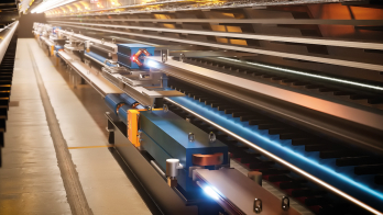
The Compact Linear Collider study aims for the high-energy frontier.
CERN’s latest and foremost accelerator, the LHC, is set to provide a rich programme of physics at a new high-energy frontier over the coming years. From 2008 onwards, the LHC will probe the new “terascale” energy region. It should above all confirm or refute the existence of the Higgs boson of the Standard Model and will explore the possibilities for physics beyond the Standard Model, such as supersymmetry, extra dimensions and new gauge bosons. The discovery potential is huge and will set the direction for possible future high-energy colliders. Nevertheless, particle physicists worldwide have reached a consensus that the results from the LHC will need to be complemented by experiments at an electron–positron collider operating in the tera-electron-volt energy range.
The highest centre-of-mass energy in electron–positron collisions so far – 209 GeV – was reached at LEP at CERN. In a circular collider, such as LEP, the circulating particles emit synchrotron radiation, and the energy lost in this way needs to be replaced by a powerful RF acceleration system. In LEP, for example, each beam lost about 3% of its energy on each turn. The biggest superconducting RF system built so far, which provided a total of 3640 MV per revolution, was just enough to keep the beam in LEP at its nominal energy. Moreover, the energy loss by synchrotron radiation increases with the fourth power of the energy of the circulating beam. So it is clear that a storage ring is not an option for an electron–positron collider operating at an energy significantly above that of LEP, as the amount of RF power required to keep the beam circulating becomes prohibitive.
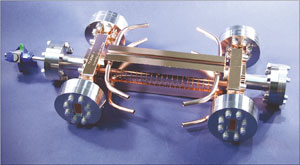
Image credit: SLAC.
Linear colliders are therefore the only option for realizing electron–positron collisions at tera-electron-volt energies. The basic principle here is simple: two linear accelerators face each other, one accelerating electrons, the other positrons, so that the two beams of particles can collide head on. This scheme has certain inherent features that strongly influence the design. First, the linacs have to accelerate the particles in one single pass. This requires high electric fields for acceleration, so as to keep the length of the collider within reasonable limits; such high fields can be achieved only in pulsed operation. Secondly, after acceleration, the two beams collide only once. In a circular machine the counter-rotating beams collide with a high repetition frequency, in the case of LEP at 44 kHz. A linear collider by contrast would have a repetition frequency of typically 5–100 Hz. This means that the luminosity necessary for the particle physics experiments can be reached only with very small beam dimensions at the interaction point and with the highest possible bunch charge. As luminosity is proportional to beam power, the overall wall-plug to acceleration efficiency is of paramount importance.
Global collaborations are currently developing two different technologies for linear colliders, each with different energy reach. The International Linear Collider (ILC) collaboration is studying a machine with a centre-of-mass energy of 500 GeV and a possible future upgrade to 1 TeV. This study is based on an RF system using superconducting cavities for acceleration, with a nominal accelerating field of 31.5 MV/m and a total length of 31 km for a colliding-beam energy of 500 GeV. The Compact Linear Collider (CLIC) study is aiming at a nominal energy of 3 TeV, and foresees building CLIC in stages, starting at the lowest energy required by the physics, with successive energy upgrades. The CLIC scheme is based on normal conducting travelling-wave accelerating structures, operating at very high electric fields of 100 MV/m to keep the total length to about 48 km for a colliding-beam energy of 3 TeV. Such high fields require high peak power and hence a novel power source – an innovative two-beam system, in which a drive beam supplies energy to the main accelerating beam. Initiated at CERN, CLIC is now a joint effort by a collaboration of 26 institutes. Although the acceleration technologies for ILC and CLIC are quite different, the two studies share many R&D issues and have developed a solid collaboration on these topics.
The linac design for CLIC is based on travelling-wave accelerating structures operating at a frequency of 12 GHz. These structures are one of the most challenging items being developed for CLIC. They have to be able to withstand the very high accelerating fields of 100 MV/m in pulses 239 ns long without being damaged by unavoidable RF breakdowns and pulsed RF heating. The image below shows the best accelerating structure produced so far. It has been tested to fields of more than 100 MV/m at nominal pulse length and with an extremely low probability of RF breakdown of less than one in 107 pulses.
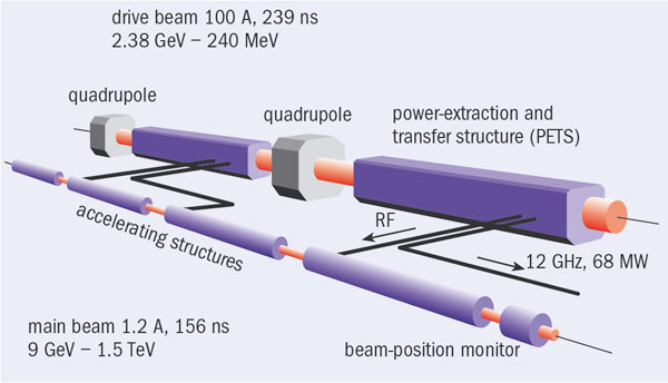
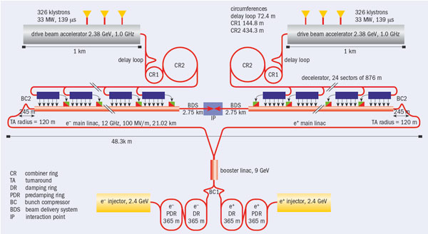
The peak RF power required to reach the electric fields of 100 MV/m amounts to about 275 MW per active metre of accelerating structure. With an active accelerator length for both linacs of 30 km out of the 48 km total length of CLIC, the use of individual RF power sources, such as klystrons, to provide such a high peak power is not really possible. Instead, the key innovative idea underlying CLIC is a two-beam scheme to produce and distribute the high peak RF-power. In this system, two beams run parallel to each other: the main beam, to be accelerated, and the drive beam to provide the RF power for the accelerating structures.
Providing the power
The drive beam is a high-current (100 A peak), low-energy (2.38 GeV) beam with a bunch repetition frequency of 12 GHz. It must contain all the energy required to accelerate the main beam, but how does it get this energy? In fact, the drive beam begins life as a long train of electron bunches (139 μs long) with large bunch spacing (60 cm). This is accelerated to an energy of 2.38 GeV using conventional klystron amplifiers at 1 GHz in a normal conducting linac. This acceleration can be made energy efficient, using the so-called fully-loaded acceleration mode, where a transfer efficiency from the RF to the beam of more than 95% has already been demonstrated in the CLIC test facility.

At this stage the drive beam contains all the energy necessary to accelerate one pulse of the main beam but with a beam current of 4.2 A. In order to get the high peak RF-power necessary for the main beam accelerating structures, the peak current of the drive beam has to be increased to 100 A. This occurs through bunch manipulations in a sequence of three rings that follow the linac: the delay loop and two combiner rings. Here, in one of the important novel features of CLIC, the bunches in 239 ns long sub-trains are interleaved between each other by injection using RF deflectors. This leads finally to bunches spaced by 2.5 cm (12 GHz) in bursts 239 ns long, with an average current during the burst of 100 A. In total, 24 such bursts follow each other, with 5.8 μs intervals between bursts.
The tunnel for CLIC will contain the elements for both the main beam and the drive beam running parallel to each other about 65 cm apart. Transfer lines to transport both beams from the injectors to the far ends of the two linacs can be installed in the same tunnel, under the ceiling.
To transfer the energy to the main beam, the drive beam passes through novel “power extraction and transfer structures” (PETS), where it excites strong electromagnetic oscillations, i.e. the beam loses its kinetic energy to electromagnetic energy. This RF energy is extracted from the PETS and sent via waveguides to the accelerating structures in the parallel main beam. The PETS are travelling-wave structures like the accelerating structures for the main beam, but with different parameters. One PETS with a different design has already been producing 30 GHz RF power in the CLIC test facility for three years.
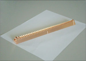
Image credit: CLIC.
A further challenge for CLIC, in common with the ILC, is to achieve the luminosity that the experiments demand. This requires beams of extremely small emittance. At CLIC, two damping rings in succession will provide the necessary reduction in each of the main beams. In the main linac itself, the RF accelerating structures have been carefully designed to control the wake fields induced by the bunches to avoid blow-up of the emittance. Finally, a sophisticated beam-delivery system focuses the beam down to dimensions of 1 nm rms size in the vertical plane and 40 nm horizontally. This requires the final focus quadrupoles to be stabilized to a vibration amplitude of less than 0.2 nm for oscillations above 4 Hz.
An important milestone will be the proof-of-principle demonstration that the major CLIC technologies are feasible. The CLIC Test Facility (CTF3), currently under construction, should demonstrate the main CLIC-specific issues by 2010.
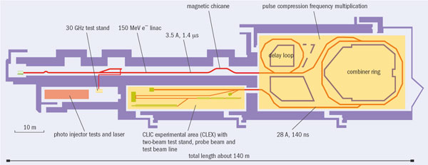
CTF3 consists of a 150 MeV electron linac, followed by a series of two rings, the delay loop and the combiner ring. This part of CTF3 is a scaled-down version of the complex required to generate the CLIC drive beam. It will demonstrate the principle of the novel bunch-interleaving technique using RF deflectors to produce the compressed drive-beam pulses. In CTF3 the compressed beam is then sent into the CLIC Experimental Hall (CLEX). This houses several beam lines where the CLIC acceleration scheme will be tested, including the extraction of RF power from the drive beam and transfer of this RF power to the accelerating structure, which will accelerate a “probe beam” in a full demonstration of the CLIC acceleration principle.
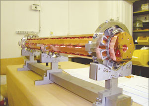
Image credit: CLIC.
Construction of CTF3 started after the closure of LEP in 2001, taking advantage of equipment from LEP’s pre-injector complex. Its installation is on schedule: the linac, delay loop and combiner ring have already been operated with beam, and further commissioning is on going. The new CLEX building is now ready, with most of the equipment installed, and it should see beam from August 2008 onwards.
The first major milestone towards CLIC will be in 2010 when the most important new technologies should be shown to be feasible, so that a conceptual design report can be published. A technical design phase will follow, including industrialization and cost optimization. Pending a decision based on physics results from the LHC, construction, which is estimated to last seven years from the moment of project approval, could then begin.
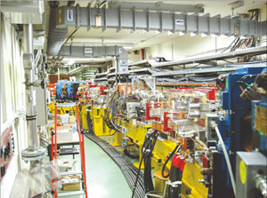
Image credit: CLIC.
• The R&D work towards CLIC is done by an international collaboration organized like those for the large particle physics experiments at CERN. It is managed by a collaboration board with representatives from the collaborating institutes, each one responsible for work packages and providing the necessary resources. The collaboration currently consists of 26 members from 14 countries: Ankara University Group (Ankara and Gazi), Budker Institute of Nuclear Physics (BINP), CEA (IRFU Saclay), CERN, CNRS IN3P3 (LAL, LAPP, LURE), DAE India (RRCAT), DOE USA (Northwestern University, Illinois, SLAC, JLAB), Helsinki Institute of Physics (HIP), IAP Nizhny Novgorod, INFN Frascati, JINR Dubna, MEC Spain (CIEMAT Madrid, IFIC Valencia, UPC Barcelona), NCP Pakistan, Norwegian Research Council (Oslo University), PSI Switzerland, STFC UK (John Adams Institute, Royal Holloway London), Ukraine Nat. Acad. Sci (IAP NASU), Uppsala University.
THE NEXT CLIC WORKSHOP
The CLIC ’08 workshop will be held at CERN on 14–17 October 2008. It is an accelerator and physics workshop, which provides a forum for those already participating in CLIC, those who are interested in joining, and any others interested in the physics and technology of CLIC. It follows the successful first workshop of this kind held in October 2007.
CLIC ’08 will cover:
* The R&D towards CLIC feasibility demonstration and conceptual design in 2010. This includes items of ILC–CLIC common interest.
* Reflections on the R&D, facilities and engineering efforts needed in the period after 2010 to progress from a conceptual design to a technical design.
* Particle physics and detector issues of a multi-TeV linear collider.
* More information about CLIC ’08 is available at http://project-clic08-workshop.web.cern.ch/.


