At 2.00 a.m. on 13 December 2008, the commissioning team at the ALICE facility of the UK’s Daresbury Laboratory and Cockcroft Institute successfully demonstrated “energy recovery” from a relativistic electron beam at 11 MeV back into the microwave source that powers the linear accelerator. Although the FEL facility and the CEBAF at Jefferson Lab in the US recently demonstrated energy recovery, this is a first for a European team.
ALICE is designed to produce ultrabright and ultrashort pulses of electrons, coherent-synchrotron radiation, FEL and tailored Compton-scattered light, which can be used – in conjunction with modern ultrafast lasers – in cutting-edge experiments in physical and life sciences. At the same time, accelerator research at the facility could revolutionize the way that high-energy particle accelerators, colliders and accelerator-based photon- and neutron-research facilities are designed in the future. A major design goal is to achieve efficient energy recovery (i.e. the repeated exchange and recycling of energy between particles and microwaves). This is a critical requirement for both the scientific reach in beam brightness and the economic viability and affordability of future high-power, high-energy particle accelerators. High-energy beams from ALICE will also be used to explore technology for new cancer treatments in a linked demonstration project known as EMMA.
After more than four years of planning and construction, ALICE achieved its first high-energy beam at 12.54 a.m. on 24 October in the 4 MeV booster. This consists of a superconducting accelerator cavity fed by a photoinjector. The photoinjector is a high-brightness electron gun capable of generating extremely short pulses of electrons, which are fired into the booster at a rate of 81 million shots a second.
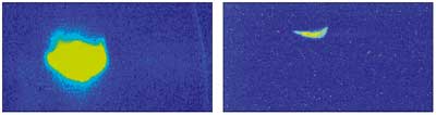
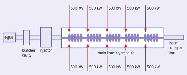
At 5.00 p.m. on 7 December, after the booster had accelerated the high-quality electron beam from the photoinjector to 4 MeV, the commissioning team took the beam from the booster up to relativistic energies of 11 MeV in a linear superconducting microwave accelerator (figure 1). The stage was then set for the final act, where the beam is threaded through 360° of beam-transport systems back to the start of the same linac. By recirculating in the opposite microwave phase, the beam undergoes deceleration to achieve energy recovery, where the energy used to accelerate the beam can be recovered and reused after each circuit of the machine.
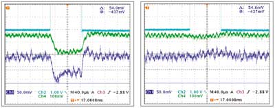
Less than a week later, at 2.00 a.m. on 13 December, the superconducting linac accelerated electrons to a total energy of 11 MeV and the beam was successfully sent round the total circuit, demonstrating energy recovery for the first time outside the US. At 10.50 p.m. on 20 December, energy recovery was achieved at 20.8 MeV (figure 2).
The next stage will be to commission the facility to its full operating energy of 35 MeV.
• ALICE is financed by the UK’s Science and Technology Facilities Council with seed funding from the North West Development Agency. It is operated by the ASTeC team within the Cockcroft Institute which is developing its advanced accelerator-research programme.
In late 2007, owing to an extended shutdown of Canada’s National Research Universal (NRU) reactor at Chalk River, North America experienced a critical shortage of the medical isotope molybdenum-99 (99Mo). Currently some 80–85% of the 40 million nuclear-medicine procedures worldwide each year use 99Mo. The NRU reactor, which has been operating since 1957, produces about half of the world’s supply. A second reactor in the Netherlands produces the balance. It too has suffered from age-related shutdowns.
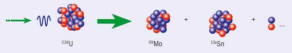
The 99Mo isotope has traditionally been manufactured using nuclear reactors to irradiate highly enriched uranium targets because high neutron fluxes are available. Now, in the light of advances in accelerators – particularly in superconducting RF (SRF) cavities that enable high beam power (Superconducting RF success) – TRIUMF, Canada’s national laboratory for particle and nuclear physics, has led a study of alternative techniques for producing 99Mo. The North American study group that was convened by TRIUMF included physics and chemistry experts, as well as clinical professionals representing industry.
The most favoured approach uses photons from a high-power electron linear accelerator to produce 99Mo from natural uranium. The researchers concluded that significant quantities of 99Mo can be produced using this method, although several laboratory experiments will be needed to establish efficiencies, equivalency of products, reliability of operation and capacity. A single multimegawatt machine could supply the entire Canadian market or 5–7% of the total North American market. The radiochemistry needed to recover and refine the 99Mo generated through photofission from natural uranium targets is likely to resemble that which is currently in use for reactors using highly enriched uranium targets. The similarity of the initial 99Mo-recovery step will depend on the volume of the target for photofission, which relies in detail on the optimization of design and performance parameters. The study group recommended the formation of a steering group, which would oversee laboratory demonstrations of the entire process, ultimately leading to a full-scale design process.
The study has attracted widespread interest in Europe, Asia and North America, with each region investigating options for securing a reliable supply of 99Mo. In many cases, however, these are highly dependent on the future plans for nuclear power, because manufacturers of power plants are likely to construct and operate their own research reactors. Canada’s five-year plan for TRIUMF (2010–2015) already includes the construction and operation of a high-power electron linear accelerator using SRF. This machine could be an important testbed for the proposed 99Mo technology because it will operate at similar power densities.
An international team led by the California Institute of Technology (Caltech), with partners from Michigan, Florida, Tennessee, Fermilab, Brookhaven, CERN, Brazil, Estonia, Korea and Pakistan, set new world records for sustained data transfer among storage systems during the successful SuperComputing 2008 (SC08) conference held in Austin, Texas, in November.
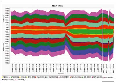
Caltech’s exhibit at SC08 by the High-Energy Physics (HEP) group and the Center for Advanced Computing Research (CACR) demonstrated new applications and systems for globally distributed data analysis for the LHC at CERN, together with Caltech’s global monitoring system, MonALISA, and its collaboration system, Enabling Virtual Organizations. A highlight of the exhibit was the HEP team’s record-breaking demonstration of storage-to-storage data transfers. This achieved a bidirectional peak throughput of 114 Gbit/s and a sustained data flow of more than 110 Gbit/s among clusters of servers on the show floor and at Caltech, Michigan, CERN, Fermilab, Brazil (Rio de Janiero, São Paulo), Korea, Estonia and locations in the US LHCNet network in Chicago, New York, Geneva and Amsterdam.
The team used a small fraction of the global LHC Grid to transfer data between the Tier-1, Tier-2 and Tier-3 facilities at the partners’ sites and between a Tier-2-scale computing and storage facility that the HEP and CACR team had constructed on the exhibit floor in fewer than two days. Rates of more than 40 Gbit/s were sustained in both directions for several hours (and up to 71 Gbit/s in one direction). One of the key elements in this demonstration was Fast Data Transfer (FDT), an open-source Java application based on TCP developed by the Caltech team in close collaboration with colleagues at Politechnica Bucharest. FDT works dynamically with Caltech’s MonALISA system to monitor the capability of the storage systems, as well as the network path, in real time. It also sends data out to the network at a rate that is matched to the capacity of long-range network paths.
A second major milestone was achieved by the HEP team working together with Ciena Corporation, which had just completed its first OTU4-standard optical link carrying a 100 Gbit/s payload over a single wavelength with forward-error correction. The teams used a fibre-optic cable with 10 fibre-pairs to link their neighbouring booths together; Ciena’s system to multiplex and demultiplex ten 10 Gbit/s links onto the single OTU4 wavelength running on an 80 km fibre loop; and some of the Caltech nodes used in setting the wide-area network records, together with FDT. Thanks to the system’s high throughput capabilities and the error-free links between the booths, the teams managed to achieve a maximum of 199.90 Gbit/s bidirectionally (memory-to-memory) within minutes, and an average of 191 Gbit/s during a 12 hour period that logged the transmission of 1.02 PB overnight.
More than 200 guests and 100 collaboration members celebrated the inauguration of the Pierre Auger Observatory at its southern site in Malargüe, Argentina, on 14 November. The event marked the completion of the first phase of the observatory construction and the beginning of the project’s second phase, which includes plans for a northern-hemisphere site in Colorado, US. Also planned are several enhancements to the southern-hemisphere site.
The Pierre Auger Collaboration began construction of its Southern Observatory in 2000. This consists of an array of 1600 detectors spread over 3000 km2 in Argentina’s Mendoza Province. Surrounding the array is a set of 24 fluorescence telescopes that view the faint ultraviolet light emitted by the cosmic-ray shower particles as they cascade through the atmosphere. More than 40 funding agencies are contributing to the observatory, which cost approximately $53 million to construct.
Guests at the inauguration ceremony included Julio Cobos, the vice-president of Argentina, Celso Jaque, the governor of Mendoza, several ambassadors, many high-level officials from funding agencies, the directors of CERN and Fermilab, and research officers from universities associated with the project. In addition to a symposium, guests enjoyed a dusty two-hour ride across the Pampa Amarilla to inspect some of the 1600 particle detectors.
Civil engineering work has started on Linac 4, a major new renovation project for the CERN accelerator complex. It will replace Linac 2 as the first link in the proton-injector chain after commissioning is completed, which is scheduled for 2013.
Linac 4 is the first project to be built in the framework of the programme of new initiatives approved by CERN Council in June last year, with additional resources amounting to SFr240 million for the period 2008–2011. The consolidation and upgrade of the LHC and its injectors figure among the initiatives and include the construction of Linac 4 and design studies for other injectors to be built in a second phase.
Linac 2 has recently celebrated 30 years of service and its replacement is an essential component of the future LHC upgrade. This aims to extend the physics reach of the machine with a gradual increase in the luminosity beyond its nominal value. The existing injector chain is the main impediment to an increase in luminosity. In addition, although of excellent and proven reliability, the injection complex is beginning to show signs of ageing: the PS will be celebrating its 50th anniversary next year.
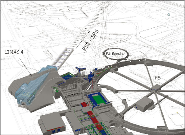
With a length of 80 m, Linac 4 will supply beams at an energy of 160 MeV, as compared with the 50 MeV beams from the 36 m long Linac 2. The new linac will feed the PS Booster, which in turn feeds the PS and then the SPS, before the particles finally enter the LHC. It will enable the PS Booster to deliver twice the beam intensity and contribute to increasing the LHC’s luminosity. Moreover, it has been designed with future upgrades in mind. In a second phase, the PS Booster will be replaced by the Superconducting Proton Linac and the venerable PS by a new machine known as PS2.
Linac 4 will use four types of accelerating structure with different focusing devices, each adapted to the beam energy. As in Linac 2, the particles are initially accelerated and focused by a RF quadrupole, and then by a drift tube linac (DTL). The DTL houses 120 specially designed permanent magnets that are smaller and more reliable than the electromagnets of Linac 2. These two initial structures will be followed by another type of linac: a cell-coupled drift tube linac, where quadrupoles are interleaved with accelerating cells. Pi-mode structures – accelerating structures similar to the copper cavities used in LEP – will provide the final boost of acceleration. Linac 4’s hardware will also include a chopper line to cut up the beam at the same frequency as that of the PS Booster (i.e. 1 MHz). Synchronizing the frequencies of the two accelerators substantially reduces the particle losses at the injection point into the PS Booster.
The Linac 4 project is part of an international collaboration. The R&D work is being undertaken as part of a European project, notably involving institutes in France, India, Italy, Russia, Pakistan and Saudi Arabia. However, in the grand tradition of CERN, some components will be recycled. For instance, the RF power will be provided by reconditioned klystrons from LEP.
Nearly a half-century ago, researchers at Stanford University began investigating superconducting RF (SRF) acceleration. They would not have been surprised to learn that by 1994, SRF had come into large-scale use in Jefferson Lab’s Continuous Electron Beam Accelerator Facility, or that by 2008 it was planned as the enormous, ultra-cold, dynamic-but-delicate heart of the proposed International Linear Collider (ILC). Nor would they be surprised to learn that this complex technology’s challenges nevertheless continue to vex accelerator builders. In my view, it’s time for the accelerator community to go back to where the pioneers at Stanford began, hit the pause button, and take a careful look at more than four decades of SRF R&D.
Such a renewed learning effort is needed because SRF technology is not only complex and vexing, it’s vital and expensive. Some 16,000 SRF accelerating cavities will be made for the ILC from hundreds of tons of the soft, ductile metal niobium, which becomes superconducting when refrigerated to nearly absolute zero. This is a major component of the ILC’s immense cost.
Niobium-based SRF is also in use or in planning at other projects – for example, Oak Ridge National Laboratory’s Spallation Neutron Source, Fermilab’s Project X, the Facility for Rare Isotope Beams, compact accelerators for university laboratories, accelerator-driven systems for nuclear power production in India, DESY’s XFEL, and energy-recovering linear accelerators driving fourth-generation light sources, such as Jefferson Lab’s free-electron laser.
Though condensed-matter physicists participated when the field began at Stanford, SRF has long since become highly specialized – maybe even too highly specialized. SRF scientists devote careers to the study of elaborate cavity design and preparation processes. Much effort has gone into development and assessment of techniques that have become standard in SRF, such as buffered chemical polishing, electropolishing and high-pressure rinsing of niobium surfaces. Much effort has been expended to overcome or circumvent the contamination problems introduced in pumping to attain the stringent vacuum conditions needed for superconducting operation.
Many of these efforts have involved, or have even begun with, the issue of the purity of the niobium material. Yet if you look back, you find that during the 1960s, Stanford’s pioneers used niobium of a purity that was not even known. The metal was electron-beam melted into the ingots from which cavities were machined. Without even addressing the purity issue, those early researchers demonstrated high performance and very high quality factors in one type of SRF cavity, the X-band pillbox cavity.
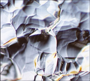
Later, to reduce the cost of larger L-band SRF cavities, researchers at Stanford switched to fine-grain niobium sheets, using 1800 °C annealing to increase the grain size – that is, to enlarge the crystals giving structure to the metal. By reducing the availability of cracks between grain boundaries, this enlargement crucially reduced the potential for hydrogen inclusion in those cracks. Hydrogen, both in the cracks and directly on the material surface, is recognized today as SRF’s major performance limiter.
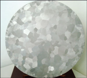
The use of high-purity niobium was not specified until later, although in the 1970s Siemens in Germany used fine-grain niobium of low purity, and demonstrated state-of-the-art peak surface magnetic fields – at levels that would still be impressive today. Researchers at Siemens enlarged the fine-grain structure with 1400 °C annealing, which led to a grain size so large as to have visible boundaries – and thus led also to a reduction in the grain-boundary inclusion of performance-degrading hydrogen.
Thanks to empirical results on three continents, it has now become apparent that SRF can progress using niobium ingot slices of merely moderate purity – that is, niobium with relaxed purity specifications, quite similar to the ingot niobium used originally at Stanford. Optimized and streamlined processes can eliminate or reduce the surface-included hydrogen, resulting in high-performance accelerator structures at reduced cost. This could mean savings of perhaps as much as a few tens of percent on ILC’s SRF cavities, and substantial operational cost savings too.
In other words, SRF’s efforts have now come full circle. The SRF researchers who followed Stanford’s original initiative have done fine work. They have made astute choices based on what they could see. But we now have a half-century of work that we can survey. The time has come to re-assess this entire R&D history. Anything less will fail to do justice to the future of accelerators – and to the future of physics itself.
With the exception of the European Synchrotron Radiation Facility, which serves an international community, all existing synchrotron light sources in Europe are located to the north of an imaginary straight line going from Paris to Trieste. To the south, Spain has only a few accelerators and these have been “turnkey” products, mainly in the medical sector; none belongs to a “big” laboratory. For these reasons, in the early 1990s the Autonomous Government of Catalonia began to consider the construction of a new, third-generation synchrotron light source.
The Generalitat de Catalunya and the Spanish Government signed a first collaboration agreement in 1995 and then took a final decision in March 2002 to create CELLS, a consortium for the construction, equipping and operation of a synchrotron light laboratory. The aim was to establish a third-generation synchrotron light source in the municipality of Cerdanyola del Vallès, in a technology area to be built next to the campus of the Autonomous University of Barcelona, some 20 km from the city. CELLS came into being at the end of 2003 with the objective of constructing the ALBA light source. The initial plan, based on an existing preliminary design study, was for a storage ring of 3 GeV with five beamlines in the first phase. This was scheduled to start up at the end of 2008, for a total cost of €164 m shared between the two administrations on a 50:50 basis.
Studies of underground characteristics, which took more than a year, led to final agreement on the 60,000 m2 site for ALBA. This was followed by project approval for the building and conventional installations, thereby guaranteeing mechanical, electrical and thermal stability. Then in 2006 the governing board of CELLS decided to extend the construction phase to the beginning of 2010, to accept two more beamlines (bringing the total to seven) and to increase the total budget to the end of 2009 to €201 m.
The facility occupies a main building of some 18,500 m2. This will host the accelerators and the experimental stations, so it must respect restrictive vibration conditions. It is built on a hard floor floating on a bed of gravel 2 m deep. There will also be peripheral auxiliary laboratories, a technical services building of 7600 m2 (including an auxiliary storage building) and an administrative building of 4000 m2.
A high-quality 12 MW power supply will be provided by a natural gas power plant that provides thermal and electrical energy, backed up by a dedicated transformer connected to a 220 kV supply line. A system of static and dynamic uninterruptible power supplies will guarantee the supply to the most critical parts of the facility.
The main elements of ALBA will be a 100 MeV linac working at a frequency of 3 GHz with a repetition rate of 3 Hz; a booster synchrotron of four-fold symmetry with an energy of 3 GeV, a circumference of 249.6 m and less than 20 nm rad emittance; and a storage ring of 268.8 m circumference located in the same tunnel as the booster. The design of the accelerators is based on the latest, but well proven, technologies. To provide as much space as possible for the installation of insertion devices and diagnostics, the design includes an extremely compact double-bend achromatic lattice of 16 cells with four-fold symmetry. It will consist of 16 pairs of combined dipole and quadrupole magnets with a central field of 1.42 T and a central gradient of 5.9 T/m, located on large girders. The lattice will be complemented by 128 quadrupole magnets and 120 sextupole magnets with more than 100 correctors installed in the sextupoles. The light source will have an emittance of 4.3 nm rad, a current of 400 mA and a critical energy of about 4.8 keV.
ALBA’s ultra-high vacuum system is made of stainless steel. To cope with the synchrotron radiation, there are antechambers all around, where water-cooled copper and Glip Cop absorbers stop the synchrotron radiation so as to avoid heating the vacuum chamber.
The radiofrequency (RF) system is based on inductive output tube (IOT) amplifiers, running at 80 kW with 67% efficiency. There will be 13: one in the booster to feed a five-cell PETRA-type cavity; and 12 in the storage ring to feed six higher-order, mode-free cavities. A new cavity combiner designed for ALBA will combine the power of the IOTs.
To obtain submicron beam stability there will be a diagnostic system based on 120 beam-position monitors and digital electronics distributed around the storage ring. In addition, synchrotron radiation monitors, current transformers, fluorescent and optical-transition-radiation screens, strip lines and annular electrodes will determine the characteristics of the electron beam. In general, standardization, modularity and robustness have been the main concerns in achieving an accelerator with high reliability and easy maintenance.
The ring will have a capacity for more than 30 beamlines. There will be 16 of these in bending magnets, three in insertion devices in long (8 m) straight sections, 12 in medium (4.4 m) straight sections and two in short (2.6 m) straight sections. The remaining straight sections will be dedicated to injection and RF.
The Asociación de Usuarios de Sincrotrón de España proposed the first phase of beam lines, seven of which CELLS accepted after consultation with the Scientific Advisory Committee. These beamlines, which are now under construction, will be dedicated as follows: one to non-crystalline diffraction and one to macromolecular crystallography, both based on in-vacuum undulators; one to photoemission spectroscopy and microscopy and one to X-ray circular magnetic dichroism, both based on normal undulators; one to X-ray absorption spectroscopy based on a multipole wiggler; one for high-resolution powder diffraction based on a superconducting wiggler; and one for X-ray microscopy based on a bending magnet. A call for a second phase of beamlines is now under way and is scheduled for approval by the end of 2009.
At present, the ALBA project is developing roughly according to budget and schedule, with a delay of only a few months, mainly owing to problems related to civil engineering and conventional services. The linac has been installed and its commissioning has finished. The civil engineering and the conventional installations will be completed in December this year. Almost all of the accelerator components have been designed, produced, tested and delivered, and installation will start soon in the main tunnel. The commissioning phase of the booster will start at the beginning of the second half of 2009 and the storage ring and beamlines will start commissioning progressively in spring 2010. By the second half of the same year the first beam lines of ALBA should be open to users.
At a little before 10.30 a.m. on 10 September, two dots on a colour screen in the CERN Control Centre (CCC) marked the successful first complete turn of protons clockwise round the LHC. It was less than an hour since the operations team began injecting Beam 1 into the machine – under the watchful eyes of the world. Lyn Evans, LHC project leader, was more than satisfied: “It was beyond my wildest dreams to get beam so quickly.”
By the end of the day, not only had the anticlockwise beam, Beam 2, also completed its first circuit but it had made some 300 turns of the machine. It was a heady experience, which was followed by a few more days of steady progress, until a breakdown in a magnet interconnection brought commissioning to a halt until next spring. However, those few days have already demonstrated that, in Evans’ words, “the machine works beautifully”.
The operations team had been preparing the SPS for injection since 8.00 a.m. and the start-up procedure with Beam 1 began promptly. At 9.30 a.m. they were ready to start, turning on the kickers to direct the beam onto a beam stop just before the interaction point at Point 2. The plan was to send in the beam one bunch at a time and open up the LHC ring step by step. At each of the four points occupied by the LHC experiments, the beam would initially be stopped by closed collimators to allow corrections to be made, if necessary. The collimators would then be opened to allow the subsequent beam shots to proceed through the detector and farther round the ring.
The sequence worked like clockwork: beam to collimators, collimators open, beam to next collimators and so on. Each of the major LHC detectors – ALICE (Point 2), CMS (Point 5), LHCb (Point 8) and ATLAS (Point 1) – lit up in turn with the first beam-related particles as bunches in Beam 1 hit the nearby collimators, creating particle “debris”.
The procedure with Beam 2 (in the anticlockwise direction) was almost as smooth. Minor problems with cryogenics delayed the start until 1.30 p.m. and slowed progress from injection at Point 8 to Point 6, where beam arrived at 1.55 p.m. Small difficulties with the beam meant that it did not reach CMS at Point 5 for another 30 minutes. However, Beam 2 had made its first complete turn by 3 p.m.
After a well deserved pause, to let the day’s achievements sink in and to gather thoughts, at 4 p.m. work in the CCC turned to the more earnest matters of studying the properties of Beam 2, and setting it up for multiple turns. Measurements over the next few hours of the kick response and dispersion showed a truly well behaved beam. By 9.30 p.m., Beam 2 orbited the LHC for at least 300 turns, just 12 hours after the first injection with Beam 1.
As the start-up of 10 September came to a close, the real work for the operations team was only just beginning. A bunch of particles travelling round the ring is a major step. However, for an accelerator the key lies in capturing the particles with the RF system that provides the accelerating electric fields – and keeping the bunches in time with the RF on the thousands of turns per second that occur during normal operation.
An essential step on the day after first beam was to turn on the RF and investigate the bunch lifetime. This was, according to Evans, one of the many worries that he had from the days when CERN gained valuable experience with its pioneering conversion of the SPS into a proton–antiproton collider. Noise from the klystrons that provide the RF power can propagate and debunch the particles.
The first tests on 11 September showed that Evans need not have worried, because the so-called “mountain range” plot revealed clearly the effects on an individual bunch on successive turns in Beam 2. Without the RF, the bunch simply broadens as particles stray from the perfect orbit round the machine; the mountain range rapidly broadens and flattens out. With the RF at the correct phase and frequency, the bunches are captured and the mountain range becomes a long, continuous narrow ridge as turn after turn the whole bunch of particles passes the same point at the right time. The result by the end of the day was what Evans called the “real champagne moment” – a perfect longitudinal bunch profile, only a day after first beam.
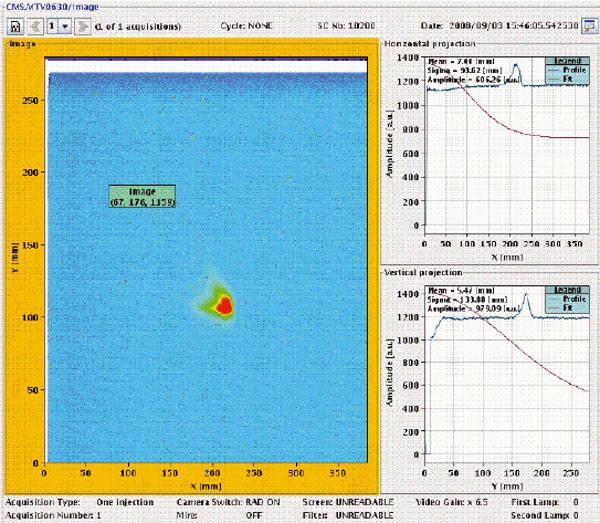
The Compact Linear Collider (CLIC) study collaboration has for the first time sent beam right to the end of the drive beamline in the CLIC Test Facility (CTF3). Early in the afternoon of 3 September, all eyes in the CTF3 control room were fixed on the camera display that showed a small beam-profile screen installed at the far end of their accelerator complex. A few minutes later the first bunch of electrons was lighting up this monitor.
Building on this success, a major effort will now go into commissioning the whole CTF3 complex to reach nominal beam parameters. CLIC’s accelerating principle is based on a two-beam scheme: a drive beam provides power for the accelerating structures, which accelerate the main beam. The programme for CTF3 foresees bringing the linac into operation for initial acceleration of the main beam, then installing and testing a first decelerating structure in the drive-beam line.
Commissioning of the LHC came to an abrupt halt at midday on 19 September, when an incident occurred in sector 3-4 that resulted in a large helium leak in the LHC tunnel. The time necessary for the investigation and repairs precludes a restart before CERN’s obligatory winter-maintenance period, pushing the date for restart of the accelerator complex to early spring 2009.
The incident occurred only nine days after the successful “first-beam” day (LHC first beam: a day to remember). During a period with no beam, owing to the replacement of a faulty transformer, the commissioning team was completing work to allow the machine to run at 5 TeV per beam, originally planned for later this year. All but one of the eight sectors had already been commissioned to 5.5 TeV before start up, and it was while bringing the magnets in sector 3-4 up to the appropriate field strengths that the incident happened. Indeed, it was the last circuit to be tested, and it had reached a current equivalent to just higher than 5 TeV.
Preliminary investigations indicate that the most likely cause of the problem was a faulty electrical connection between two magnets, which probably melted at high current, leading to a rupture of the helium vessel and the release of high-pressure gas into the cyrostat. The gas then discharged into the tunnel through the pressure-relief valves designed for this purpose. At the same time, the quench-protection circuits on some 100 magnets fired, all working perfectly to protect the magnets as foreseen. A sector consists of 154 main superconducting dipoles plus straight sections with 40 main quadrupoles and various other magnets. CERN’s strict safety regulations ensured that at no time was there any risk to people.
The LHC, like other major particle accelerators, has been built at the cutting edge of technology but with unprecedented complexity, owing to its unique two-in-one superconducting magnet system. No fewer than 123,000 interconnections were needed for the 27 km ring, including 65,000 electrical connections with superconducting cables. All the other circuits had passed their tests to 9000 A with flying colours.
A full investigation of the incident is underway, but the whole sector must be warmed up to room temperature and the magnets involved opened up for inspection before this can be completed. Only at this stage will the extent of collateral damage caused by the sudden release of helium be fully known. The warm up is expected to be completed towards the end of October.
To provide the best experiences, we use technologies like cookies to store and/or access device information. Consenting to these technologies will allow us to process data such as browsing behavior or unique IDs on this site. Not consenting or withdrawing consent, may adversely affect certain features and functions.
Functional
Always active
The technical storage or access is strictly necessary for the legitimate purpose of enabling the use of a specific service explicitly requested by the subscriber or user, or for the sole purpose of carrying out the transmission of a communication over an electronic communications network.
Preferences
The technical storage or access is necessary for the legitimate purpose of storing preferences that are not requested by the subscriber or user.
Statistics
The technical storage or access that is used exclusively for statistical purposes.The technical storage or access that is used exclusively for anonymous statistical purposes. Without a subpoena, voluntary compliance on the part of your Internet Service Provider, or additional records from a third party, information stored or retrieved for this purpose alone cannot usually be used to identify you.
Marketing
The technical storage or access is required to create user profiles to send advertising, or to track the user on a website or across several websites for similar marketing purposes.