Image credit: M Brice.
The Antiproton Decelerator (AD) facility at CERN, which has been operational since 2000, is a unique source of antimatter. It delivers antiprotons with very low kinetic energies, enabling physicists to study the fundamental properties of baryonic antimatter – namely antiprotons, antiprotonic helium and antihydrogen – with great precision. Comparing the properties of these simple systems to those of their respective matter conjugates therefore provides highly sensitive tests of CPT invariance, which is the most fundamental symmetry underpinning the relativistic quantum-field theories of the Standard Model (SM). Any observed difference between baryonic matter and antimatter would hint at new physics, for instance due to the existence of quantum fields beyond the SM.
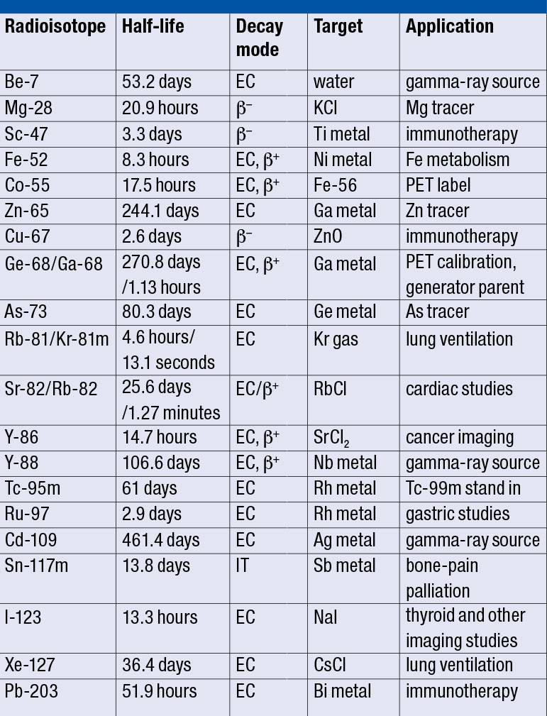
In the case of matter particles, physicists have developed advanced experimental techniques to characterise simple baryonic systems with extraordinary precision. The mass of the proton, for example, has been determined with a fractional precision of 89 parts in a trillion (ppt) and its magnetic moment is known to a fractional precision of three parts in a billion. Electromagnetic spectroscopy on hydrogen atoms, meanwhile, has allowed the ground-state hyperfine splitting of the hydrogen atom to be determined with a relative accuracy of 0.7 ppt and the 1S/2S electron transition in hydrogen to be determined with a fractional precision of four parts in a quadrillion – a number that has 15 digits.
ELENA will lead to an increase by one to two orders of magnitude in the number of antiprotons captured by experiments
In the antimatter sector, on the other hand, only the mass of the antiproton has been determined at a level comparable to that in the baryon world (see table). In the late 1990s, the TRAP collaboration at CERN’s LEAR experiment used advanced trapping and cooling methods to compare the charge-to-mass ratios of the antiproton and the proton with a fractional uncertainty of 90 ppt. This was, among others, one of the crucial steps that inspired CERN to start the AD programme. Over the past 20 years, CERN has made huge strides towards our understanding of antimatter (see panel). This includes the first ever production of anti-atoms – antihydrogen, which comprises an antiproton orbited by a positron – in 1995 and the production of antiprotonic helium (in which an antiproton and an electron orbit a normal helium nucleus).
CERN has decided to boost its AD programme by building a brand new synchrotron that will improve the performance of its antiproton source. Called the Extra Low ENergy Antiproton ring (ELENA), this new facility is now in the commissioning phase. Once it enters operation, ELENA will lead to an increase by one to two orders of magnitude in the number of antiprotons captured by experiments using traps and also make new types of experiments possible (see figure). This will provide an even more powerful probe of new physics beyond the SM.
Combined technologies
The production and investigation of antimatter relies on combining two key technologies: high-energy particle-physics sources and classical low-energy atomic-physics techniques such as traps and lasers. One of the workhorses of experiments in the AD facility is the Penning trap. This static electromagnetic cage for antiprotons serves for both high-precision measurements of the fundamental properties of single trapped antiprotons and for trapping large amounts of antiprotons and positrons for antihydrogen production.
The AD routinely provides low-energy antiprotons to a dynamic and growing user community. It comprises a ring with a circumference of 182.4 m, which currently supplies five operational experiments devoted to studying the properties of antihydrogen, antiprotonic helium and bare antiprotons with high precision: ALPHA, ASACUSA, ATRAP, AEgIS and BASE (see panel). All of these experiments are located in the existing experimental zone, covering approximately one half of the space inside the AD ring. With this present scheme, one bunch containing about 3 × 10⁷ antiprotons is extracted roughly every 120 seconds at a kinetic energy of 5.3 MeV and sent to a particular experiment.

Although there is no hard limit for the lowest energy that can be achieved in a synchrotron, operating a large machine at low energies requires magnets with low field strengths and is therefore subject to perturbations due to remanence, hysteresis and external stray-field effects. The AD extraction energy of 5.3 MeV is a compromise: it allows beam to be delivered under good conditions given the machine’s circumference, while enabling the experiments to capture a reasonable quantity of antiprotons. Most experiments further decelerate the antiprotons by sending them through foils or using a radiofrequency quadrupole to take them down to a few keV so that they can be captured. This present scheme is inefficient, however, and less than one antiproton in 100 that have been decelerated with a foil can be trapped and used by the experiments.
The ELENA project aims to further decelerate the antiprotons from 5.3 MeV down to 100 keV in a controlled way. This is achieved via a synchrotron equipped with an electron cooler to avoid losses during deceleration and to generate dense bunches of antiprotons for users. To achieve this goal, the machine has to be smaller than the AD; a circumference of 30.4 metres has been chosen, which is one sixth of the AD. The experiments still have to further decelerate the beam either using thinner foils or other means, but the lower energy from the synchrotron makes this process more efficient and therefore increases the number of captured antiprotons dramatically.
With ELENA, the available intensity will be distributed to several (the current baseline is four) bunches, which are sent to several experiments simultaneously. Despite the reduction in intensity, the higher beam availability for a given experiment means that a given experiment will receive beam almost continuously 24 hours per day, as opposed to during an eight-hour-long shift a few times per week, as is the case with the present AD.
The ELENA project started in 2012 with the detailed design of the machine and components. Installations inside the AD hall and inside the AD ring itself began in spring 2015, in parallel to AD operation for the existing experiments. Installing ELENA inside the AD ring is a simple cost-effective solution because no large additional building to house a synchrotron and a new experimental area had to be constructed, plus the existing experiments have been able to remain at their present locations. Significant external contributions from the user community include a H– ion and proton source for commissioning, and very sensitive profile monitors for the transfer lines.
Low-energy challenges
Most of the challenges and possible issues of the ELENA project are a consequence of its low energy, small size and low intensity. The low beam energy makes the beam very sensitive to perturbations such that even the Earth’s magnetic field has a significant impact, for instance deforming the “closed orbit” such that the beam is no longer located at the centre of the vacuum chamber. The circumference of the machine has therefore been chosen to be as small as possible, thus demanding higher-field magnets, to mitigate these effects. On the other hand, the ring has to be long enough to install all necessary components.

For similar reasons, magnets have to be designed very carefully to ensure a sufficiently good field quality at very low field levels, where hysteresis effects and remanence become important. This challenge triggered thorough investigations by the CERN magnet experts and involved several prototypes using different types of yokes, resulting in unexpected conclusions relevant for any project that relies on low-field magnets. The initially foreseen bending magnets based on “diluted” yokes, with laminations made of electrical steel alternated with thicker non-magnetic stainless steel laminations, were found to have larger remnant fields and to be less suitable. Based on this unexpected empirical observation, which was later explained by theoretical considerations, it has been decided that most ELENA magnets will be built with conventional yokes. The corrector magnets have been built without magnetic yoke to completely suppress hysteresis effects.
Electron cooling is an essential ingredient for ELENA: cooling on an intermediate plateau is applied to reduce emittances and losses during deceleration to the final energy. Once the final energy is reached, electron cooling is applied again to generate dense bunches with low emittances and energy spread, which are then transported to the experiments. At the final energy, so-called intra beam scattering (IBS) caused by Coulomb interactions between different particles in the beam increases the beam “emittances” and the energy spread, which, in turn, increases the beam size. This phenomenon will be the dominant source of beam degradation in ELENA, and the equilibrium between IBS and electron cooling will determine the characteristics of the bunches sent to the experiments.
Another possible limitation for a low-energy machine such as ELENA is the large cross-section for scattering between antiprotons and the nuclei of at-rest gas molecules, which leads to beam loss and degradation. This phenomenon is mitigated by a carefully designed vacuum system that can reach pressures as low as a few 10–12 mbar. Furthermore, ELENA’s low intensities and energy mean that the beam can generate only very small signals and therefore makes beam diagnostics challenging. For example, the currents of the circulating beam are less than 1 μA, which is well below what can be measured with standard beam-current transformers and therefore demands that we seek alternative techniques to estimate the intensity.
An external source capable of providing 100 keV H– and proton beams will be used for a large part of the commissioning. Although this allows commissioning to be carried out in parallel with AD operation for the experiments, it means that commissioning starts at the most delicate low-energy part of the ELENA cycle where perturbations have the most impact. Another advantage of ELENA’s low energy is that the transfer lines to the experiments are electrostatic – a low-cost solution that allows for the installation of many focusing quadrupoles and makes the lines less sensitive to perturbations.
CERN's AD facility opens new era of precision anitmatter studies

CERN’s Antiproton Decelerator (AD) was approved in 1997, just two years after the production of the first antihydrogen atoms at the Low Energy Antiproton Ring (LEAR), and entered operation in 2000. Its debut discovery was the production of cold antihydrogen in 2002 by the ATHENA and ATRAP collaborations. These experiments were joined by the ASACUSA collaboration, which aims at precision spectroscopy of antiprotonic helium and Rabi-like spectroscopy of the antihydrogen ground-state hyperfine splitting. Since then, techniques have been developed that allow trapping of antihydrogen atoms and the production of a beam of cold antihydrogen atoms. This culminated in 2010 in the first report on trapped antihydrogen by the ALPHA collaboration (the successor of ATHENA). In the same year, ASACUSA produced antihydrogen using a cusp trap, and in 2012 the ATRAP collaboration also reported on trapped antihydrogen.
TRAP, which was based at LEAR and was the predecessor of ATRAP, is one of two CERN experiments that have allowed the first direct investigations of the fundamental properties of antiprotons. In 1999, the collaboration published a proton-to-antiproton charge-to-mass ratio with a factional precision of 90 ppt based on single-charged-particle spectroscopy in a Penning trap using data taken up to 1996. Then, published in 2013, ATRAP measured the magnetic moment of the antiproton with a fractional precision of 4.4 ppm. The BASE collaboration, which was approved in the same year, is now preparing to improve the ATRAP value to the ppb level. In addition, in 2015 BASE reported on a comparison of the proton-to-antiproton charge-to-mass ratio with a fractional precision of 69 ppm. So far, all measured results are consistent with CPT invariance.
The ALPHA, ASACUSA and ATRAP experiments, with the goal of performing precise antihydrogen spectroscopy, are challenging because they need antihydrogen first to be produced and then to be trapped. This requires the accumulation of both antiprotons and positrons, in addition to antihydrogen production via three-body reactions in a nested Penning trap. In 2012, ALPHA reported on a first spectroscopy-type experiment and published the observation of resonant quantum transitions in antihydrogen (see figure) and, later, ASACUSA reported in 2014 on the first production of a beam of cold antihydrogen atoms. The reliable production/trapping scheme of ALPHA, meanwhile, enabled several high-resolution studies, including the precise investigation of the charge neutrality of antihydrogen with a precision at the 0.7 ppb level.
The ASACUSA, ALPHA and ATRAP collaborations are now preparing their experiments to produce the first electromagnetic spectroscopy results on antihydrogen. This is difficult because ALPHA typically reports on about one trapped antihydrogen atom per mixing cycle, while ASACUSA detects approximately six antihydrogen atoms per shot. Both numbers demand for higher antihydrogen production rates, and to further boost AD physics, CERN built the new low-energy antiproton synchrotron ELENA. In parallel to these efforts, proposals to study gravity with antihydrogen were approved. This led to the formation of the AEgIS collaboration in 2008, which is currently being commissioned, and the GBAR project in 2012.
Towards first beam
As of the end of October 2016, all sectors of the ELENA ring –except for the electron cooler, which has temporarily been replaced by a simple vacuum chamber, and a few transfer lines required for the commissioning of the ring – have been installed and baked to reach the very low rest-gas density required. Following hardware tests, commissioning with beam is under way and will be resumed in early 2017, only interrupted for the installation of the electron cooler some time in spring.
ELENA will be ready from 2017 to provide beam to the GBAR experiment, which will be installed in the new experimental area (see panel). The existing AD experiments, however, will be connected only during CERN’s Long Shutdown 2 in 2019–2020 to minimise the period without antiprotons and to optimise the exploitation of the experiments. GBAR, along with another AD experiment called AEgIS, will target direct tests of the weak-equivalence principle by measuring gravitational acceleration based on antihydrogen. This is another powerful way to test for any violations between the way the fundamental forces affect matter and antimatter. Although the first antimatter fall experiments were reported by the ALPHA collaboration in 2013, these results will potentially be improved by several orders of magnitude using the dedicated gravity experiments offered by ELENA.
ELENA is expected to operate for at least 10 years and be exploited by a user community consisting of six approved experiments. This will take physicists towards the ultimate goal of performing spectroscopy on antihydrogen atoms at rest, and also to investigate the effect of gravity on matter and antimatter. A potential discovery of CPT violation will constitute a dramatic challenge to the relativistic quantum-field theories of the SM and will potentially contribute to an understanding of the striking imbalance of matter and antimatter observed on cosmological scales.