The recent Future Circular Collider (FCC) workshop, held online from 9 to 13 November, brought together roughly 500 scientists, engineers and stakeholders to prepare a circular-collider-oriented roadmap towards the realisation of the vision of the European strategy for particle physics: to prepare a Higgs factory followed by a future hadron collider with sensitivity to energy scales an order of magnitude higher than at the LHC.
The meeting combined the fourth FCC physics week with the kick-off event for the EU-funded Horizon 2020 FCC Innovation Study (FCCIS). A successor to the previous EuroCirCol project, which was completed in 2019 and supported the preparation of the FCC conceptual design report (CDR), it will support the preparation of a feasibility study of a 100 km-circumference collider that could host an intensity- frontier electron–positron Higgs and electroweak factory (FCC-ee), followed by a 100 TeV energy-frontier hadron collider (FCC-hh) – an integrated scheme that EuroCirCol showed to be doable “in principle”. Key advantages of the FCC design are the multiple interaction points, high beam luminosities and long-term science mission covering both precision and energy frontiers over several decades (see FCC-ee: beyond a Higgs factory). The design must now be validated. “The feasibility study of FCC is particularly challenging and will require the hard work, dedication and enthusiasm of the full FCC community,” noted CERN Director-General Fabiola Gianotti.
Unprecedented capabilities
The main goal of the study, said FCC-study project-leader Michael Benedikt, is to demonstrate the practical feasibility of delivering the unprecedented luminosities and precise energy-calibration capabilities of the proposed electroweak factory in a modular fashion. The study will also incorporate a socio-economic impact analysis and an implementation plan for an infrastructure that could fit in the global research landscape, he said. The feasibility study – a “CDR++” – will be prepared by 2025/2026, in time for the next strategy update.
A key consideration for FCC-ee that was discussed at the meeting is the development of a complete collider design with full beam-dynamic simulations and a complete injector. Continuous top-up injection, from a full-energy booster ring installed next to the collider, will lead to stable operation and maximum integrated luminosity, offering availability for physics runs of more than 80%. A series of tests in research facilities around Europe, including at PETRA-III (DESY), KARA (KIT), DAΦNE (Frascati), and potentially other facilities such as VEPP-4M (BINP), will provide the opportunity to validate the concepts. Developing a staged superconducting radio-frequency system is another major challenge. Multi-cell 400 MHz Nb/Cu cavities required for the Higgs-factory operation mode will be available within five years, alongside a full cryomodule. A mock-up of a 25 m-long full-arc half-cell of the FCC-ee is expected for 2025. Such cells will cover about 80 km of FCC-ee’s 100 km circumference.
Physics-analysis questions were also at the forefront of participants’ minds. “We are confronted with three deep and pressing questions when we observe our universe,” noted ECFA chair Jorgen D’Hondt. “What is the mechanism responsible for the transition from massless to massive particles? What are the processes that lead to the breaking of symmetry between particles and antiparticles? And how is the observed universe connected to what remains invisible to us?” Theorist Christopher Grojean (DESY) showed that electroweak, Higgs and flavour data from FCC-ee, in conjunction with astrophysical and cosmological observations, have the potential to break through the armour of the Standard Model and begin to tackle these questions. Discussions explored the need to halve theoretical uncertainties and hone detector designs to match the high statistical precision offered by the FCC-ee, and the possibility of complementing FCC-ee with a linear collider such as the proposed International Linear Collider, which could access higher energies.
Strong message
The November FCC workshop paved the way for progress beyond the state-of-the-art in a variety of areas that could ensure the sustainable and efficient realisation of a post-LHC collider. A strong message from the workshop was that the FCC feasibility study must be a global endeavour that attracts industrial partners to co-develop key technologies, and inspires the next generation of particle physicists.
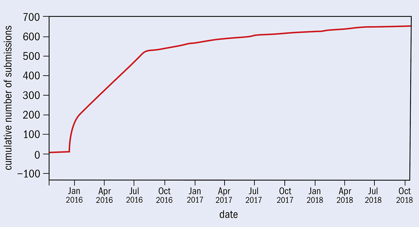
In June 2020, the CMS collaboration submitted a paper titled “Observation of the production of three massive gauge bosons at √s= 13 TeV” to the arXiv preprint server. A scientific highlight in its own right, the paper also marked the collaboration’s thousandth publication. ATLAS is not far from reaching the same milestone, currently at 964 publications. With the rest of the LHC experiments taking the total number of papers to 2852, the first ten years of LHC operations have generated a bumper crop of new knowledge about the fundamental particles and interactions.
The publication landscape in high-energy physics (HEP) is very exceptional due to a long-held preprint culture. From the 1950s paper copies were kept in the well-known red cabinets outside the CERN Library (pictured), but since 1991 they have been stored electronically at arXiv.org. Preprint posting and actual journal publication tend to happen in parallel, and citations between all types of publications are compiled and counted in the INSPIRE system.
Particle physics has been at the forefront of the open-science movement, in publishing, software, hardware and, most recently, data. In 2004, former Director-General Robert Aymar encouraged the creation of SCOAP3 (Sponsoring Consortium for Open Access Publishing in Particle Physics) at CERN. Devoted to converting closed access HEP journals to open access, it has grown extensively and now has over 3000 libraries from 44 different countries. All original LHC research results have been published open access. The first collaboration articles by the four main experiments, describing the detector designs, and published in the Journal of Instrumentation, remain amongst the most cited articles from LHC collaborations and — despite being more than a decade old — are some of the most recently read articles of the journal.
Closer analysis
Since then, along with the 2852 publications by CERN’s LHC experiments, a further 380 papers have been written by individuals on behalf of the collaboration, and another 10,879 articles (preprints, conference proceedings, etc.) from the LHC experiments that were not published in a journal. However, this only represents part of the scientific relevance of the LHC. There were tens of thousands of papers published over the past decade that write about the LHC experiments, use their data or are based on the LHC findings. The papers published by the four experiments received on average 112 citations per paper, compared to an average of 41 citations per paper across all experimental papers indexed in INSPIRE and even 30 citations per paper across all HEP publications (4.8 million citations across 163,000 documents since 2008). Unsurprisingly, the number of citations peaks with the CMS and ATLAS papers on the Higgs discovery, with 10,910 and 11,195 citations respectively, which at the end of 2019 were the two most cited high-energy physics papers released in the past decade.
Large author numbers are another exceptional aspect of LHC-experiment publishing, with papers consistently carrying hundreds or even thousands of names. This culminated in a world record of 5,154 authors on a joint paper between CMS and ATLAS in 2015, which reduced the uncertainty on the measurement of the Higgs-boson mass to ±0.25%.
Teasing fluctuations
Ten years of LHC publications have established the Standard Model at unprecedented levels of precision. But they also reveal the hunger for new physics, as illustrated by the story of the 750 GeV diphoton ‘bump’. On 15 December 2015, ATLAS and CMS presented an anomaly in data that showed an excess of events at 750 GeV in proton collisions, fueling rumours a new particle could be showing itself. While the significance of the excess was only 2σ and 1.6σ respectively, theorists were quick to respond with an influx of hundreds of papers (see “750 shades of model building”). This excitement was however damped by the release of the August 2016 data, where there was no further sign of the anomaly, and it became commonly recognised as a statistical fluctuation – part and parcel of the scientific process, if ruining the fun for the theorists.
With the LHC to continue operations to the mid-2030s, and only around 6% of its expected total dataset collected so far, we can look forward to thousands more publications about nature’s basic constituents being placed in the public domain.
The significant increase in luminosity targeted by the high-luminosity LHC (HL-LHC) demands large-aperture quadrupole magnets that are able to focus the proton beams more tightly as they collide. A total of 24 such magnets are to be installed on either side of the ATLAS and CMS experiments in time for HL-LHC operations in 2027, marking the first time niobium-tin (Nb3Sn) magnet technology is used in an accelerator.
Nb3Sn is a superconducting material with a critical magnetic field that far exceeds that of the niobium-titanium presently used in the LHC magnets, but once formed it becomes brittle and strain-sensitive, which makes it much more challenging to process and use.
The milestone signals the end of the prototyping phase for the HL-LHC quadrupoles
Giorgio Apollinari
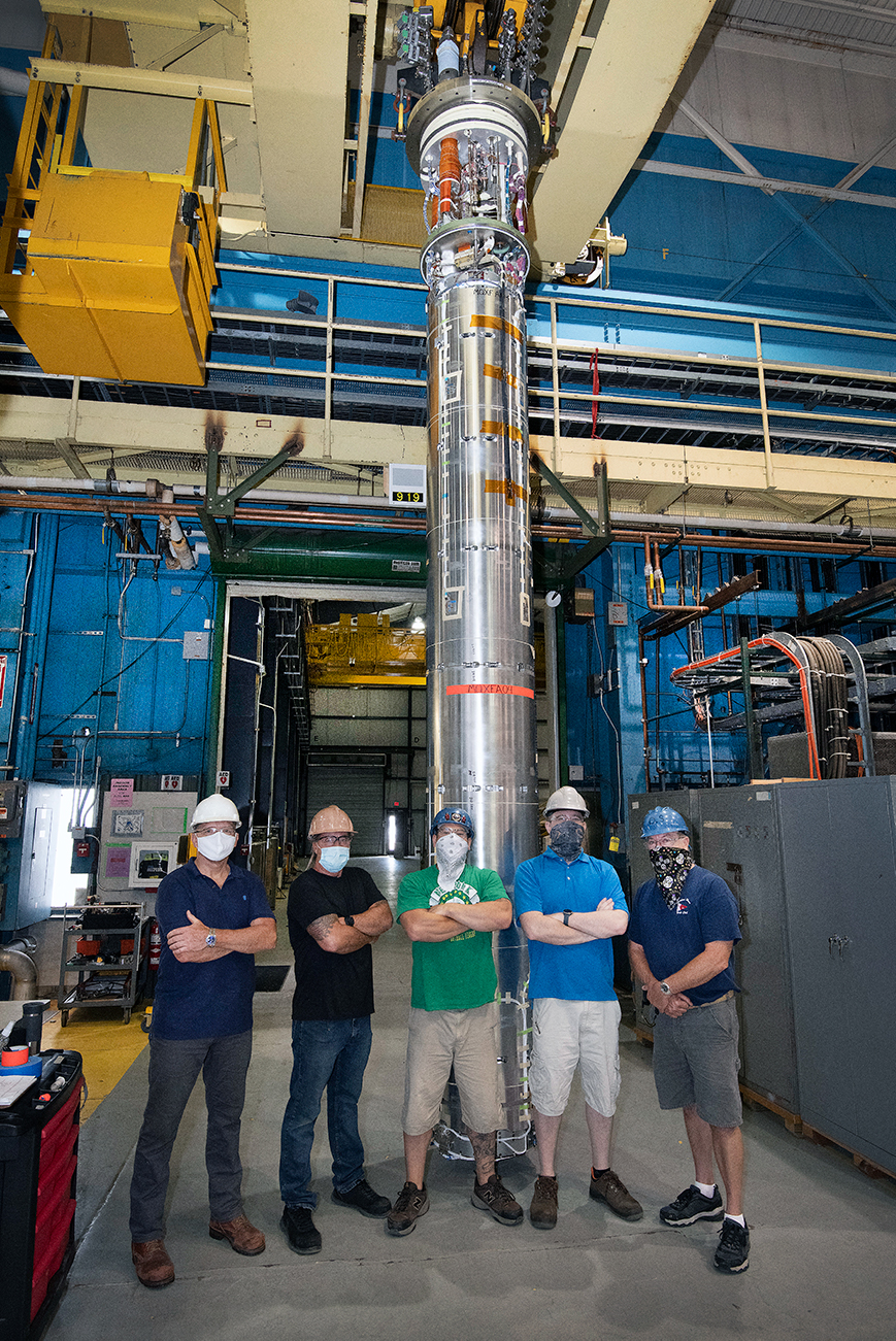
Following the first successful test of a US-built HL-LHC quadrupole magnet at Brookhaven National Laboratory (BNL) in January last year—attaining a conductor peak field of 11.4 T and exceeding the required integrated gradient of 556 T in a 150 mm-aperture bore—a second quadrupole magnet has now been tested at BNL at nominal performance. Since the US-built quadrupole magnets must be connected in pairs before they can constitute fully operational accelerator magnets, the milestone signals the end of the prototyping phase for the HL-LHC quadrupoles, explains Giorgio Apollinari of Fermilab, who is head of the US Accelerator Upgrade Projects (AUP). “The primary importance is that we have entered the ‘production’ period that will make installation viable in early 2025. It also means we have satisfied the requirements from our funding agency and now the US Department of Energy has authorised the full construction for the US contribution to HL-LHC.”
Joint venture
The design and production of the HL-LHC quadrupole magnets are the result of a joint venture between CERN, BNL, Fermilab and Lawrence Berkeley National Laboratory, preceded by the 15 year-long US LHC Accelerator Research Program (LARP). The US labs are to provide a total of ten 9 m-long helium-tight vessels (eight for installation and two as spares) for the HL-LHC, each containing two 4.2 m-long magnets. CERN is also producing ten 9 m-long vessels, each containing a 7.5 m-long magnet. The six magnets to be placed on each side of ATLAS and CMS – four from the US and two from CERN – will be powered in series on the same electrical circuit.
The synergy between CERN and the US laboratories allowed us to considerably reduce the risks
Ezio Todesco
“The synergy between CERN and the US laboratories allowed us to considerably reduce the risks, have a faster schedule and a better optimisation of resources,” says Ezio Todesco of CERN’s superconductors and cryostats group. The quadrupole magnet programme at CERN is also making significant progress, he adds, with a short-model quadrupole having recently reached a record 13.4 T peak field in the coil, which is 2 T more than the project requirements. “The full series of magnets, sharing the same design and built on three sites, will also give very relevant information about the viability of future hadron colliders, which are expected to rely on massive, industrial production of Nb3Sn magnets with fields up to 16 T.”
Since the second US quadrupole magnet was tested in October, the AUP teams have completed the assembly of a third magnet and are close to completing the assembly of a fourth. Next, the first two magnets will be assembled in a single cold mass before being tested in a horizontal configuration and then shipped to CERN in time for the “string test” planned in 2023.
“In all activities at the forefront of technology, like in the case for these focusing Nb3Sn quadrupoles, the major challenge is probably the transition from an ‘R&D mentality’, where minor improvements can be a daily business, to a ‘production mentality’, where there is a need to build to specific procedures and criteria, with all deviations being formally treated and corrected or addressed,” says Apollinari. “And let’s not forget that the success of this second magnet test came with a pandemic raging across the world.”
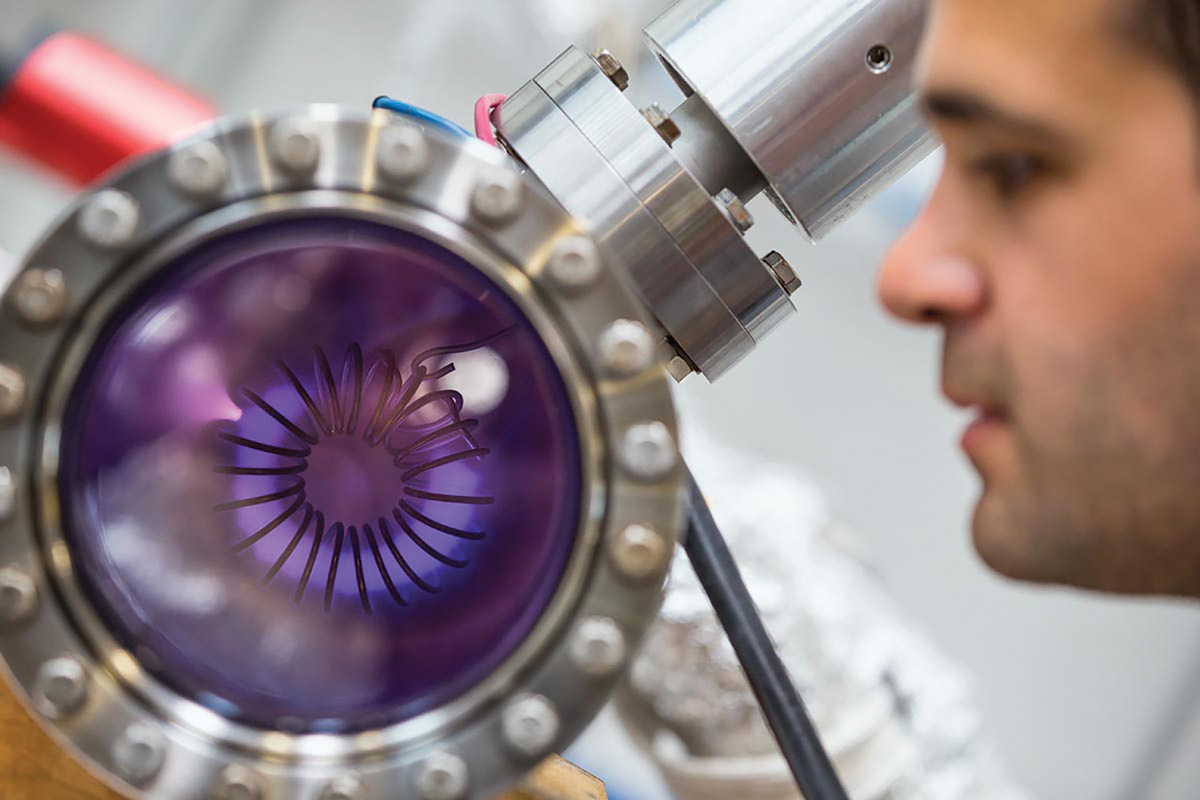
After seven years of construction at the Joint Institute for Nuclear Research (JINR) in Dubna, Russia, the Booster synchrotron at the brand-new NICA (Nuclotron-Based Ion Collider Facility) Complex has accelerated its first beam. On 19 December helium ions were injected into the synchrotron and a stable circulation of the beam was obtained at an energy of 3.2 MeV. The milestone marks an important step in establishing the NICA facility, which is estimated to be completed by 2022.
At this energy, ordinary matter and the quark-gluon plasma coexist in a mixed phase
The NICA accelerator complex will allow studies of the properties of nuclear matter in the region of maximum baryonic density. By colliding heavy gold ions at energies corresponding to the deconfinement phase transition (4.5 GeV), NICA will access the transition of the quark-gluon plasma (QGP) into hadrons. At this energy, ordinary matter and the QGP are able to exist in a so-called mixed phase – complementing studies at higher energy colliders such as the LHC.
The NICA booster is a 211 m circumference superconducting synchrotron which will accelerate beams to 500 MeV. It uses 2.2 m-long dipole and quadrupole magnets made up of a window frame iron yoke and a winding made of a hollow niobium-titanium superconducting cable cooled with a two-phase helium flow. Beams will then be transported to a separate ring surrounding the booster, the “nuclotron”, and accelerated to the GeV range. The nuclotron was originally built between 1987 and 1992 as part of the Dubna “syncrophasotron modernisation” programme, and was Europe’s first superconducting accelerator of heavy ions to high energies. Finally, beams will be injected into two identical 503 m storage rings, which will collide the beams at two detectors: the Multi-Purpose Detector (MPD) and the Spin-Physics Detector (SPD). The MPD facility is designed to study dense baryonic matter, while SPD will study collisions between polarised beams of protons and deuterons.
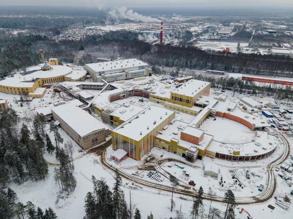
The complex is one of six Russian “megascience” facilities that are part of the CREMLIN project, which aims to use large-scale science facilities to improve and strengthen relations and networks between European and Russian research infrastructures. The CREMLIN consortium comprises 19 European and Russian research infrastructures, including CERN, and DESY. Other “megascience” facilities included in this project are the Super-Charm-Tau Factory at the Budker Institute of Nuclear Physics, and the Special-purpose Synchrotron-Radiation Source (SSRS-4) at the NRC Kurchatov Institute.
“This is a historical moment for our Laboratory and a great milestone in realization of our flagship megascience project – we have to thank the grant programme CREMLIN helping us in these challenges,” says Vladimir Kekelidze, the NICA project leader. “The final step before the physical launch of the Booster will be the adjustment of the beam acceleration mode, which will then allow focus to switch to the construction of the beam transport systems from the Booster to the Nuclotron.”
Materials exposed to the high-energy beams in a particle accelerator must fulfil a demanding checklist of mechanical, electrical and vacuum requirements. While the structural function comes from the bulk materials, many other properties are ascribed to a thin surface layer, sometimes just a few tens of nanometres thick. This is typically the case for the desorption caused by electron, photon and ion collisions; Joule-effect heating induced by the electromagnetic field associated with the particle beams; and electron multipacting phenomena (see “Collaboration yields vacuum innovation”). To deliver the required performance, dedicated chemical and electrochemical treatments are needed – and more often than not mandatory – to re-engineer the physical and chemical properties of vacuum component/subsystem surfaces.
The bigger drivers here are the construction and operation of the Large Hadron Collider (LHC) and the High-Luminosity LHC upgrade – projects that, in turn, have driven impressive developments in CERN’s capabilities and infrastructure for surface chemistry and surface modification. The most visible example of this synergy is the new Building 107, a state-of-the-art facility that combines a diverse portfolio of chemical and electrochemical surface treatments with a bulletproof approach to risk management for personnel and the environment. Operationally, that ability to characterise, re-engineer and fine-tune surface properties has scaled dramatically over the last decade, spurred by the recruitment of a world-class team of scientists and engineers, the purchase of advanced chemical processing systems, and the consolidation of our R&D collaborations with specialist research institutes across Europe.
Chemistry in action
Within CERN’s Building 107, an imposing structure located on the corner of Rue Salam and Rue Bloch, the simplest treatment to implement – as well as the most common – is chemical surface cleaning. After machining and handling, any accelerator component will be contaminated by a layer of dirt – mainly organic products, dust and salts. Successful cleaning requires the right choice of materials and production strategy. A typical error in the design of vacuum components, for example, is the presence of surfaces that are hidden (and so difficult to clean) or holes that cannot be rinsed or dried fully. Standard cleaning methods to tackle such issues are based on detergents that, in aqueous solution, will lower the surface tensions and so aid the rinsing of foreign materials like grease and dust.
Successful cleaning requires the right choice of materials and production strategy
The nature of the accelerator materials means there are also secondary effects of cleaning that must be considered at the design phase – e.g. removal of the oxide layer (pickling) for copper and etching for aluminium alloys. To improve the cleaning process, we apply mechanical agitation via circulation of cleaning fluids, oscillation of components and ultrasonic vibration. The last of these creates waves at a frequency higher than 25 kHz. In the expansion phase of the liquid waves, microbubbles of vapour are generated (cavitation), while in the compression phase the bubbles implode to generate pressures of around 1000 bar at the equipment surface – a pressure so high that the material can be eroded (though the higher the frequency, the smaller the gas bubbles and the less aggressive the surface interaction).
Chemical fine-tuning
An alternative cleaning method is based on non-aqueous solvents that act on contamination by dilution. Right now, modified alcohols are the most commonly used solvents at CERN – a result of their low selectivity and minimal toxicity – with the cleaning operation performed in a sealed machine to minimise the environmental impacts of the volatile chemicals. While the range of organic products on which solvents are effective is usually wider than that of detergents, they cannot efficiently remove polar contaminants like salt stains. Another drawback is the risk of contaminants recollecting on the component surface when the liquid does not flow adequately.
Ultimately, the choice of detergent versus solvent relies on the experience of the operator and on guidelines linked to the type of vacuum component and the nature of the contamination. In general, the coating of components destined for ultrahigh-vacuum (UHV) applications will require a preliminary cleaning phase with detergents. Meanwhile, solvents are the optimum choice when there are no stringent cleanliness requirements – e.g. degreasing of filters for cryoplants or during the component assembly phase – and for surfaces that are prone to react with or retain water – e.g. steel laminations for magnets, ceramics and welded bellows. (It is worth noting that trapped water is released in vacuum, compromising the achievement of the required pressure, while wet surfaces are seeds for corrosion in air.)
After rinsing and drying, the components are then ready for installation in the accelerator or for ongoing surface modification. In the case of the latter, the chemical treatments aim to generate a thinner, more compact oxide layer and/or a smoother surface – essential for subsequent plating processes. As such, the components can undergo etching, pickling and passivation (to reduce the chemical reactivity of the surface). Consider the copper components for the LHC’s current-lead support: before brazing (a joining process using a melted filler metal), these components are pickled in hydrochloric acid and passivated in chromic acid. Similarly, the aluminium contacts of busbars (for local high-current power distribution) must be pickled by caustic soda and/or a mixture of nitric and hydrofluoric acid before silver coating. Another instructive example is found in the LHCb’s Vertex Locator (VELO) detector, in which the aluminium RF-box window is thinned down to 150 microns by caustic soda.
Safety-critical thinking is hard-wired into the operational DNA of CERN’s Building 107, underpinning the day-to-day storage, handling and large-scale use of chemical products for surface treatments. That safety-first mantra means the 5000 m2 facility is able to confine all hazards inside its walls, such that risks for the surrounding neighbourhood and environment are negligible. Among the key features of Building 107:
• There are retention basins that allow containment of the liquid from all surface-treatment tanks (plus, even in the unlikely case of a fire, there is enough retention capacity for the water pumped by the firefighting teams).
• The retention basins have leak detection sensors, pumping systems, buffer tanks and a special coating that’s able to withstand more than 100 types of chemical for several days in the event of a leak.
• Toxic and corrosive vapours are extracted continuously from the tanks and washed in dedicated scrubbers, while any escaped solvents are adsorbed on active carbon filters.
• A continuous spray of alkaline solution transfers toxic products (liquid phase) for decontamination at CERN’s wastewater treatment plant.
• In terms of fire prevention, all plastics used for the treatment tanks and extraction ducts are made of self-extinguishing polypropylene – removing the source of energy to sustain the flames.
• The safety of technicians is ensured by strict operating procedures (including regulated building access), enhanced air extraction and the storage of incompatible products in separate retention zones.
• State-of-the-art sensors provide permanent monitoring of critical airborne products and link to local and fire-brigade alarms.
Frequently, chemical or electrochemical polishing are required in addition to cleaning. Polishing removes the damaged subsurface layer generated by lamination and machining – essentially a tangle of voids, excess dislocations and impurities. In this context, it is worth highlighting the surface treatments for RF acceleration cavities. Best practice dictates that materials for such applications – essentially niobium and copper – must undergo chemical and/or electrochemical polishing to remove a surface layer of 150 micron thickness. As such, the final state of the material’s topmost layer is flawless and without residual stress. (Note that while mechanical polishing can achieve lower roughness, it leaves behind underlayer defects and abrasive contaminations that are incompatible with the high-voltage operation of RF cavities.) A related example is the niobium RFD crab cavity for the HL-LHC project. This complex-shaped object is treated by a dedicated machine that can provide rotation while chemically polishing with a mixture of nitric, hydrofluoric and phosphoric acids. In this chemical triple-whammy, the first acid oxidises niobium; the second fluorinates and “solubilises” the oxide; and the last acts as a buffer controlling the reaction rate.
Another intriguing opportunity is the switch from wet to dry chemistry for certain niche applications
The final set of treatments involves plating the component with a functional material. In outline, this process works by immersing the accelerator component (negatively biased) into an electrolytic solution containing the functional metal ions. The electrolytic solution is strongly acid or basic to ensure high electrical conductivity, with deposition occurring via reduction of the metallic ions on the component surface – all of which occurs in dedicated tanks where the solution is heated, agitated and monitored throughout.
At CERN, we have extensive experience in the electroplating of large components and can plate with copper, silver, nickel, gold and rhodium. Copper is by far the most common option and its thickness is frequently of the order of hundreds of microns (while gold and rhodium are rarely thicker than a few microns). Current capacity varies from 7 m-long pipes (around 10 cm diameter) to 3.5 m-long tanks (up to 0.8 m diameter). It is worth noting that these capabilities are also used to support other big-science facilities – including a recent implementation for the Drift Tube Linac tanks of the European Spallation Source (ESS) in Lund, Sweden.
Chemical innovation
Notwithstanding the day-to-day provision of a range of surface treatments, the Building 107 chemistry team is also tasked with driving process innovation. As safety is our priority, the main focus is on the replacement of toxic products with eco- and personnel-friendly chemicals. A key challenge in this regard is to substitute chromic acid and cyanate baths, and ideally limit the current extensive use of hydrofluoric acid – a development track inextricably linked to the commercialisation of new products and close cooperation with our partners in industry.
Elsewhere, the chemistry team has registered impressive progress on several fronts. There’s the electroforming of tiny vacuum chambers for electron accelerators and RF cavities with seamless enclosure of flanges at the extremities. This R&D project is supported by CERN’s knowledge transfer funds and has already been proposed for the prototyping of the vacuum chamber of the Swiss Light Source II. A parallel line of enquiry includes production of self-supported graphite films for electron strippers that increase the positive charge of ions in beams – with the films fabricated either by etching the metallic support or by electrochemical delamination (a technique already proposed for the production of graphene foils).
Another intriguing opportunity is the switch from wet to dry chemistry for certain niche applications. A case in point is the use of oxygen plasmas for surface cleaning – a technique hitherto largely confined to industry but with one notable exception in accelerator science. The beryllium central beam pipes of the four main LHC experiments, for example, were cleaned by oxygen plasma before non-evaporable-getter coating, removing carbon contamination without dislodging atoms of the hazardous metal. Following on from this successful use case, we are presently studying oxygen plasmas for in situ decontamination and cleaning of radioactive components, a priority task for the chemistry team as the HL-LHC era approaches.
The future of surface chemistry at CERN looks bright – and noticeably greener. The Building 107 team, for its part, remains focused on developing chemical surface treatments that are, first and foremost, safer and, in some cases, drier.
Tom Kammermeier is an industrial physicist in a hurry. Hardly surprising given that the commercial roadmap he’s following points to a multibillion-dollar opportunity for vacuum equipment makers – an opportunity that, in turn, promises to transform ground-based mass-transportation of people and goods over the coming decades using energy-efficient hyperloop technologies.
Put simply: if technology hype translates into commercial reality, today’s proof-of-principle hyperloop test facilities will, ultimately, scale up to enable the transit of passenger and freight capsules from A to B through steel tubes (roughly 4 m in diameter) maintained at partial vacuum (typically less than 1 mbar). The end-game: journeys of several hundred kilometres at speeds in excess of 1000 km/h – Los Angeles to San Francisco, Mumbai to Chennai, Montreal to Toronto are just some of the high-demand routes on the drawing board – with maglev technologies teed up to provide the required propulsion, acceleration and deceleration along the way.
The end-game for hyperloop is journeys of several hundred kilometres at speeds in excess of 1000 km/h
While the journey to commercial hyperloop deployment is only just beginning, a thriving and diverse innovation ecosystem is already hard at work, with heavily financed technology start-ups and dozens of academic groups and established manufacturers coalescing into a nascent hyperloop supply chain. As Leybold’s global application development manager (industrial vacuum), Kammermeier is front-and-centre in the German manufacturer’s efforts to establish itself as the “go-to” vacuum technology partner for the hyperloop development community. Here he talks to CERN Courier about the trade-offs, challenges and near-term benefits of playing the long game on technology strategy.
How does your application development team support technical and commercial outcomes within Leybold?
I coordinate a team of 20 application specialists worldwide who handle what we call third-level product support – essentially any unique or non-standard technical requests that get referred to us by our regional sales and field engineering colleagues. In each case, we’ll work closely with Leybold’s product engineering and R&D teams to come up with solutions, ensuring that any new learning and insights are shared across the organisation through a structured programme of knowledge dissemination – online webinars, tutorial videos and the like. Our remit also includes the investigation and development of new vacuum applications. This work is informed by emerging customer needs in markets where Leybold already has an established presence – for example, surface coatings, semiconductors, solar technology and food and drink – as well as evaluation of longer-range commercial applications like hyperloop transportation.
What’s the back-story to Leybold’s engagement with the hyperloop community?
The hyperloop opportunity was initially championed at Leybold back in 2015 by my colleague Carl Brockmeyer, who at the time was head of new business development (and is now president of Leybold’s scientific vacuum division). While Carl articulated the long-term commercial vision, my team focused on initial simulations and high-level requirements-gathering for the enabling vacuum technologies. At the outset, we worked closely with pioneering development companies such as Hyperloop Transportation Technologies (HTT) in the US and Virgin Hyperloop (US), while subsequent collaborations include TransPod (Canada) and the EuroTube Foundation (Switzerland).
I’m a physicist by training and, from the off, it was evident to me that there are no insurmountable technical barriers to hyperloop transportation. As such, it seems clear that the large-scale deployment of hyperloop systems will ultimately be driven by policy-makers and by commercial factors such as capital/operational costs versus return on investment.
Hyperloop represents a long-term commercial opportunity for Leybold. Are there any near-term upsides?
The calculus is simple: in the absence of volume orders, we invest time and resources in early-stage R&D collaborations with leading hyperloop companies in return for the publicity, benefits of association and the acquisition of technical and commercial domain knowledge. The work is bursty and comes in waves – essentially an R&D programme and reciprocal learning exercise at this stage. More widely, we’re seeing some payback in our established market sectors, where the hyperloop activity has opened doors with new customers who might not know Leybold so well. What we see is that hyperloop is a great topic for our sales teams to talk about – it’s very relatable.
What do these hyperloop collaborations typically involve?
Our approach is project-led, bringing together ad hoc teams of engineering, simulation and application specialists to address a range of customer requirements. Most of our collaborations to date have kicked off with simulation studies – a relatively cheap way to test the water and build a fundamental understanding of hyperloop vacuum systems and their core technologies.
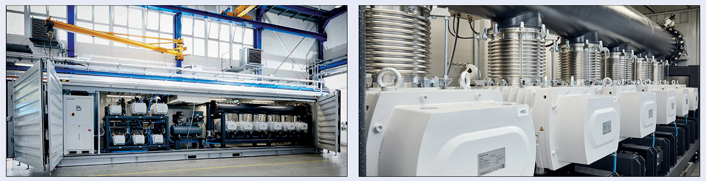
It wasn’t long, however, before our systems group began supplying one-off hardware orders, including a large-scale vacuum pumping unit for Virgin Hyperloop’s DevLoop test facility in the Nevada desert. While this is a custom installation, it’s
based on existing commercial pumping units that we sell into steel degassing applications, though with several modifications to the programmable controller.
There’s been lots of hype about hyperloop over the last five years. How do you see the market trajectory right now?
My take is that hyperloop R&D and commercialisation activities are gathering pace, as evidenced by the first successful demonstration of human travel in a hyperloop pod at Virgin Hyperloop’s DevLoop test site back in October. This represents a significant breakthrough after more than 400 previously unoccupied test-runs at DevLoop. Elsewhere, we recently sold another big pumping system into HTT for its work-in-progress test-track near Toulouse, France. We’re frequently in contact with them regarding simulation or engineering considerations, with safety-critical aspects very much to the fore as HTT also plans to transport human passengers in the near future.
What sort of technical challenges is Leybold being asked to address by hyperloop developers?
Pumping down a hyperloop vacuum tube over hundreds of kilometres is a non-trivial engineering challenge. From a vacuum perspective, you need to think carefully about the spacing of your pumping stations along the tube; optimisation of each pumping system; what happens in case of tube failures or accidents; and how the distributed pumping network can provide back-up pumping capacity and compensation (see “Hyperloop: rewriting the rules of large-scale vacuum”).
Hyperloop: rewriting the rules of large-scale vacuum
“Pumping down a hyperloop vacuum tube over hundreds of kilometres is a non-trivial engineering challenge,” notes Leybold’s Tom Kammermeier in our accompanying interview. Here he outlines some of the key design and engineering considerations for hyperloop vacuum systems.
Location, location, location
The aspect ratio (diameter/length) of a hyperloop system is enormous – 1/1000,000 is easily within reach – and imposes inescapable design constraints in terms of vacuum pumping capability. A single-site pumping station, while minimising capital outlay, would result in some odd pressure distributions and gradients along the hyperloop track. During pump-down, for example, the operator might register the target base pressure at one end of the pipe while the other end is still at atmospheric pressure. What’s needed instead is an intelligent distribution of pumping capacity along the track – crucial for compensation of any leaks and pump failures, and doubly so in terms of reducing capital/operational expenditure (as every additional pumping site means more outlay in terms of enclosures, power supply, water supply and associated infrastructure).
Smart strategies for leak management
A vacuum system can be defined along a number of coordinates, not least in terms of its pump-down requirements and target operating pressure (where the total pumping speed equals the inleak flow rate). The higher the permissible operating pressure, the lower the pumping speed, and the greater the aggregate energy savings over time. A large-scale hyperloop system will therefore require a smart pumping network to optimise the distribution of pumping speed dynamically versus local inleak flow conditions – a capability that, in turn, will yield significant (and recurring) operational savings. It’s also worth noting that an understanding of the pumping-speed distribution (essentially a granular map of pressure along the tube) will enable efficient leak detection without recourse to a conventional and time-consuming leak search.
Gearing up, pumping down
Peak energy consumption for any hyperloop vacuum system will occur during end-to-end pump-down along the track. With this in mind, Leybold is working to optimise its multistage Roots pumping systems for the very long pump-downs (of the order of 12–24 hours) that will be required in large-scale hyperloop tubes. Roots pumps are an excellent option for high-volume flows at low pressures – i.e. the usual operating regime of hyperloop systems – but their efficient use for an extended pump-down from atmospheric pressure is problematic. Issues can include overheating due to gas compression; overload of the motor; or exceeding temperature limits due to low heat dissipation at low gas pressures. The answer is to employ variable-speed drives, which basically “know” the thermodynamics of each individual pump and enable optimised use. In this way, the programmable logic controller of the pumping system is able to orchestrate the individual pumps to yield the highest possible pumping speed during a pump-down – equating to some millions of m3/h for a 1000 km track.
What lessons have you learned from Leybold’s engagement with the hyperloop community?
A lot of the learning here has been around the simulation of large-scale distributed vacuum systems – because no-one has ever built a vacuum system on the scale necessary to support commercial hyperloop transportation. We’ve had plenty of discussions to date regarding our models and whether they’re still valid over distances of several hundred kilometres, while our technology roadmap focuses on what an optimised pumping system will look like for future “live” hyperloop deployments. To date, because the market is still not mature enough, we’ve created smart hyperloop pumping systems by adapting our existing product lines – specifically, units that we’ve developed for steel-industry applications.
Is cost a big driver of your hyperloop R&D priorities?
Always. Cost-of-ownership calculations feature prominently in discussions with all our hyperloop customers. We’ve given a lot of input, for example, on required pumping speed versus leak flow rate versus operating pressure. Fundamental studies like this help our partners to evaluate whether it’s worth focusing more of their investments on a leak-tight pipe or on the vacuum pumping systems. Another priority for developers is energy consumption, so our system-level simulations provide vital insights for the accurate calculation of pump-down time and vacuum performance versus energy budget. In this context, it’s worth noting that Leybold’s DRYVAC Energy Saver – which reduces the energy consumption of our dry compressing screw pumps and systems by as much as 50% – is emerging as a potential game-changer for the large-scale pumping systems that will underpin hyperloop installations.
Are vacuum equipment makers ready if hyperloop’s technology push translates into market pull?
If hyperloop transportation really takes off, it will represent a massive growth market for the vacuum industry. Even a mid-size hyperloop project will require significant focus and scale-up from suppliers like Leybold. The biggest challenge will be developing, then bringing to market, a new generation of application-specific pumping systems – at the required scale and the right price-points.
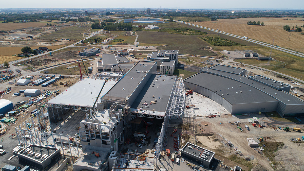
Neutron science 2.0 is evolving from concept to reality as construction progresses on the European Spallation Source (ESS), a €1.84 billion accelerator-driven neutron source in Lund, Sweden. ESS will deliver first science in 2023 and will, when in full operation, be the world’s most powerful neutron research facility – between 20 and 100 times brighter than the Institut Laue-Langevin (ILL) in Grenoble, France, and up to five times more powerful than the Spallation Neutron Source (SNS) in Oak Ridge, Tennessee, US.
This industrial-scale endeavour represents an amalgam of the most powerful linear proton accelerator ever built; a two-tonne, rotating tungsten target wheel (which produces neutrons via the spallation process); a reference set of 22 state-of-the-art neutron instruments for user experiments (of which 15 are under construction); and a high-performance data management and software development centre (located in Copenhagen). Here, Marcelo Juni Ferreira, vacuum group leader at ESS, tells CERN Courier how vacuum technologies are equally fundamental to the ESS’s scientific programme.
What does your role as ESS vacuum group leader involve?
I head up a 12-strong multidisciplinary team of engineers, scientists, designers and technicians who manage the international network of stakeholders developing the vacuum infrastructure for the ESS. Many of our partners, for example, make “in-kind” contributions of equipment and personnel rather than direct cash investments from the ESS member countries. As such, the ESS vacuum group is responsible for maintaining the facility’s integrated vacuum design approach across all of these contributions and all of our vacuum systems – the proton accelerator, target section, neutron beamlines and the full suite of neutron instruments that will ultimately support user experiments (see “ESS science, funding and partnership”).
In terms of specifics, what is meant by integrated vacuum design?
The integrated approach to vacuum design works on several levels. Cost reduction is a fundamental driver for ESS. The use of standard industry components where possible reduces maintenance and training requirements, minimises the need for expensive product inventory and, through a single framework agreement covering our in-kind partners and industry suppliers, we can work at scale to lower our overall procurement costs.
Another motivation is to help the vacuum group support the diverse vacuum requirements across the neutron instruments. The goal in each case is to ensure sustainable, economical and long-term operation of each instrument’s vacuum plant to minimise downtime and maximise research output. To make this possible, each of the neutron instruments (and associated beamlines) has its own “vacuum interface” document summarising key technical specifications and performance requirements – all ultimately aligned with the ESS Vacuum Handbook, the main reference source promoting the use of common vacuum equipment and standards across all aspects of the project.
So, standardisation is a big part of your vacuum strategy?
Absolutely. It’s all about a unified approach to our vacuum equipment as well as the procurement policy for any major hardware/software purchases for the accelerator, the target and the neutron instruments. Another upside of standardisation is that it simplifies the interfaces between the ESS vacuum infrastructure and the ESS safety and control plant – for example, the personnel protection, machine protection and target safety systems.
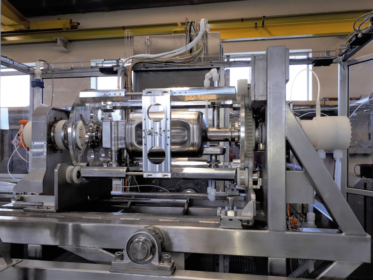
ESS recently took delivery of the Target Monolith Vessel (TMV), one of the facility’s main vacuum sections. What is the TMV and who built it?
The TMV represents the core building block of the ESS target station and was assembled by our in-kind partners at ESS Bilbao, Spain, working in collaboration with local manufacturers such as Cadinox and AVS. When ESS goes online in 2023, the TMV will enclose all of the target subsystems – the target wheel, moderator, reflector plugs and cryogenic cooling – in a vacuum atmosphere and, with the help of 6000 tonnes of stainless-steel shielding, also confine any activated materials and ionising radiation in case of a highly unlikely event, such as an earthquake or accident (see “ESS operational highlights”).
The monolith is an impressive and complex piece of precision engineering in its own right. The vessel requires exacting and repeatable alignment tolerances (±25 μm) for the target wheel, the moderator and reflector assemblies relative to the incident proton beam as well as the neutron-beam extraction system. Ahead of shipping, ESS Bilbao successfully completed the leak and vacuum tests on the TMV with satisfactory measurements of dew-point temperature, pressure rise and leak detection. The final pressure obtained was 1 × 10⁻⁶mbar with a leakage < 1 × 10⁻⁸ mbar.l/s.
In terms of the TMV, how does your team design and build for maximum uptime?
The focus on project risk is a collective effort across all support functions and is framed by the ESS Strategic Installation and Test Strategy. With the TMV, for example, our design choices seek to minimise service interruptions to the scientific experiments at ESS. Put another way: each vacuum component in the TMV must offer the longest “time before failure” available on the market. In the case of the rough vacuum pumps, for example, this comes from Kashiyama Industries of Japan through ESS’s supplier Low2High Vacuum in Sweden – offering a dry vacuum pump that’s capable of 24/7, maintenance-free operation for up to three years. We’ve actually tested six of these units running at the laboratory for more than five years and none of them have required any intervention.
ESS science, funding and partnership
• Large-scale neutron facilities are routinely used by academic and industrial researchers to understand material properties on the atomic scale, spurring advances across a spectrum of scientific discovery – from clean energy and environmental technology to pharma and healthcare, from structural biology and nanotech to food science and cultural heritage.
• ESS is a pan-European project with 13 European nations as members: the Czech Republic, Denmark, Estonia, France, Germany, Hungary, Italy, Norway, Poland, Spain, Sweden, Switzerland and the UK.
• Significant in-kind contributions of equipment and expertise – from more than 40 European partner laboratories – are expected to finance more than a third of the overall construction costs for ESS.
• ESS will deliver its first science in 2023, with up to 3000 visiting researchers expected every year once the lab is fully operational.
Smart choices like this add up and result in less maintenance, reduced manual handling of active materials (e.g. pump oil) and lower cost per unit life-cycle. Similar thinking informs our approach regarding the TMV’s vacuum “plumbing”. The use of aluminium gaskets and clamps, for example, streamlines installation (compared with CF flanges) and takes into account their low neutron activation in the case of maintenance removal and reassembly ahead of resumed operations (with hands-on manipulation being faster and simpler in each case).
What are the biggest operational challenges in terms of preparing the TMV for high-reliability vacuum performance?
The major effort on the vessel was – and still is – to qualify all in-vacuum parts and connections in terms of their leak rates, pressure-code requirements and surface finishing. This includes the water-cooled shielding blocks, hydrogen-cooled moderator/deflector, and the helium cooling unit for the rotating tungsten target wheel (which employs a ferrofluidic sealing system). It’s a huge collective effort in vacuum: there are more than 1000 flanges, around 20,000 bolts and 6000 tonnes of load in the fully configured TMV (which measures 6 m internal diameter and 11 m high).
There will be two possible modes of TMV operation, with the target residing in either high vacuum or helium at slightly below atmospheric pressure. What’s the rationale here?
One of the high-level design objectives for ESS states that the TMV should be built to last for 50 years of operation while satisfying all performance and safety criteria. Our initial simulations showed that “cleanliness” of the volume surrounding the collisions of the proton beam and the tungsten target wheel will be essential for slowing material degradation and therefore delivering against this objective. What’s more, the specification of a 5 MW proton beam means that secondary gamma and neutron radiation will be produced as a side-effect of the spallation process, further emphasising the need for a controlled environment as well as appropriate cooling of the shielding blocks to counter radiation-induced heating effects.
• At the heart of the ESS is a linear accelerator that produces up to a 5 MW beam of 2 GeV protons, with the bulk of the acceleration generated by more than 100 superconducting radio-frequency (RF) cavities.
• These accelerated protons strike a rotating tungsten target wheel (2.6 m diameter) to produce a beam of neutrons via nuclear spallation – i.e. the impact on the tungsten nuclei effectively “spalls” off free neutrons.
• The target wheel rotates at 23.3 rpm and is cooled by a flowing helium gas system interfaced with a secondary water system.
• The spalled neutrons pass through water premoderators, a supercritical hydrogen moderator (cooled to about 17 K) and a beryllium-lined reflector – all of which are housed in a replaceable plug – to slow the neutrons to useful energies before distribution to a suite of 15 neutron-science instruments.
• The TMV has an Active Cells Facility to perform remote handling, disassembly and storage of components that are taken out of the monolith after reaching the end of their lifetime; steel shielding blocks prevent the escape of neutron/gamma ionising radiation.
TMV vacuum considerations
• The TMV is designed to accommodate various leak-rate loads, including: outgassing of vacuum components; air leaks into the vacuum vessel; water leaks from internal piping plus humidity and condensation present during operations and pump down; and helium leaks from the target wheel.
• Total gas in-leakage is critical and, in conjunction with the capacity of the turbomolecular pumping system, will determine not only the TMV operating pressure but also the refrigeration capacity for the cryo-condensing coil for pumping of potential water leaks.
• In vacuum mode, TMV pressures < 10–4 mbar will be required for interfacing with the UHV environment of the proton accelerator (i.e. to keep gas flows into the accelerator section to an acceptable level).
• TMV vacuum components (including polymer seals) must be compatible with operation up to 35 °C in harsh gamma/neutron radiation environments.
Operationally, the optimal mode of operation will be high vacuum (< 10–4 mbar), which will negate the need for a proton beam window between the proton accelerator and the target. This, in turn, will lower the annual operating costs. Other advantages include up to 1% improved neutronic performance, reduced beam scattering on the TMV components (and therefore less heat load and radiation damage), as well as a cleaner image for the beam imaging diagnostics.
Nevertheless, we will design and build a proton beam window, so that it is ready to install for operation under helium should an unanticipated issue arise with the TMV vacuum. Worth noting that in this “helium mode” a pump-and-purge capability is provided to ensure high helium purity (> 99.9%).
What lessons can other big-science facilities learn from your experiences with the ESS vacuum project?
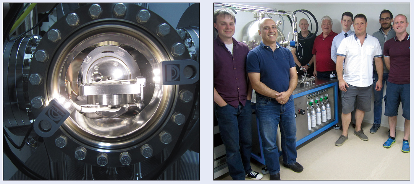
With ESS we are entering new territory and the reliability of all our components – vacuum and otherwise – requires close collaboration as well as consistent communication on all levels with our equipment vendors and in-kind partners. Operationally, there’s no doubt that the TMV and the other ESS vacuum systems have benefited from our dedicated vacuum laboratory – one of the first in-kind hardware shipments back in 2015 – and our efforts to recruit and build a skilled team of specialists in those early days of the project. The laboratory includes test facilities for vacuum integration, gauge calibration and materials outgassing studies – capabilities that allow us to iterate and optimise field solutions in good time ahead of deployment. All of which ultimately helps us to minimise project risk, with technical decisions informed by real-world testing and not just prior experience.
Vacuum represents a core enabling technology in particle accelerators. Without the required degree of vacuum, the rate of interaction between circulating particles and residual gas molecules would generate several adverse conditions. Particle beams would increase in size and so decrease in luminosity at the interaction points. Beam instability and the rate of particle loss would grow, endangering instrumentation and increasing the background noise in physics experiments. Induced radioactivity and bremsstrahlung radiation would increase risks for personnel and cause damage to the accelerator hardware. What’s more, vacuum is crucial for avoiding electrical breakdown in high-voltage equipment, as well as for thermal insulation of cryogenic fluids, reducing heat “inleaks” to acceptable levels.
Operationally, the level of vacuum required for particle accelerators spans a large range of residual gas densities – from high vacuum (HV, 10–3 to 10–9 mbar) through ultrahigh vacuum (UHV, 10–9 to 10–12 mbar) to extreme high vacuum (XHV, usually defined as 10–12 mbar and lower). Applications in thermal insulation, for example, require a gas-molecule density 10 million times lower than sea-level atmospheric pressure – i.e. less than 10–4 mbar. On the other hand, a modern synchrotron facility requires UHV residual gas densities of ≤ 10–9 mbar, while some antimatter experiments impose a rarefaction requirement in the region of 10–15 mbar. In the most challenging experiments, vacuum is an enclosed space where only several gas molecules per cm3 persist in their random motion, bouncing from one wall of the vacuum vessel to another and able to travel thousands of millions of km before striking another peer (roughly equivalent to the distance from the Sun to Jupiter).
Writ large, it is no surprise that, with more than 125 km of beampipes and liquid-helium transfer lines, CERN is home to one of the world’s largest vacuum systems – and certainly the longest and most sophisticated in terms of particle accelerators. From HV to the UHV/XHV regimes, the complexity of vacuum systems for the particle accelerators at CERN, and other big-science laboratories like it, stems largely from the interaction between particle beams and the surfaces that surround them.
Beam interactions
This “beam–surface dialogue” induces gas desorption from the vacuum system walls, an interaction that can be the dominant source of gas. Indeed, if atmospheric gas is evacuated rapidly from the vacuum system, with no in-leakage of air, it is possible to attain UHV conditions in just a few hours for chamber volumes of the order of a cubic metre. Although the vacuum-system walls release gases spontaneously – mainly water vapour and hydrogen – the choice of suitable materials and thermal treatments reduces the outgassing rates to an acceptable level before accelerator operation. As such, beam-induced gas desorption remains the biggest headache – and this effect, of course, arises only when the particle beams are in circulation.
Beam losses on the chamber walls can be a direct source of gas in the accelerator vacuum system. For the most part, however, beam-induced gas desorption occurs indirectly via the emission of synchrotron light and the beam-induced acceleration of electrons and ions created, for example, by residual gas ionisation. The synchrotron-light-induced desorption is mediated by surface–electron quantum transitions leading to the extraction of photoelectrons, which can desorb residual gas molecules in two ways – initially when leaving the chamber wall, also when striking the wall subsequently. This effect is by far the main source of gas in circular high-energy electron accelerators and plays a significant role in the Large Hadron Collider (LHC), where the critical energy of the emitted photons is around 40 eV (i.e. large enough to extract photoelectrons and induce desorption).
It’s worth noting, though, that there’s no “instant fix” for excessive gas desorption. Even with appropriate chemical surface treatments, accelerator vacuum systems (particularly those for electrons) cannot cope with full beam performance on day one of commissioning. Instead, it is necessary to ramp up the performance of the vacuum system while the beam current is increased in a stepwise fashion. In this way, the dose of particles hitting the surfaces of the vacuum vessel increases (though without excessive beam losses), while desorption yields are reduced via surface cleaning and chemical modification. In the jargon, this optimisation of surface conditioning is known as a “scrubbing run”.
The time taken for surface conditioning can be cut dramatically with the help of nonevaporable getter (NEG) coatings, a concept developed at CERN in the late 1990s. Put simply: the beampipe walls are coated with a micrometre-thick film of Ti–Zr–V alloy that, once heated for a few hours in the accelerator at about 200 °C, provides a clean metal surface that also acts as a pump (i.e. gas molecules are adsorbed by chemical reaction at the surface). During heating, the main reservoir of gas is eliminated as the oxide passivation layer dissolves into the film; after which the cycle repeats whenever adsorption of gas molecules saturates the surface or air venting is necessary.
This NEG capability is deployed at scale by CERN. The 6 km-long beam lines of the LHC’s room-temperature straight sections, for example, are coated entirely with NEG materials, while uptake in several synchrotron research facilities is now envisaged after a pioneering implementation in MAX IV, the Swedish synchrotron. In summary: NEG coatings combine distributed, high-speed pumping with negligible space requirements – a win–win for small-diameter beampipes in the current generation of electron accelerators.
Another significant component of the beam–surface dialogue within particle accelerators is the heating of materials exposed to the circulating beams. One of two possible tracks for the transfer of thermal power is the interaction between the electromagnetic field generated by the beams with the surrounding materials, a process that induces electrical currents on the beam-facing surfaces.
Support for projects like the HL-LHC requires full cognisance of some pretty harsh operating environments
These currents may in turn give rise to Joule heating, typically mitigated by using a good electrical conductor (like copper) as the material of choice for the beampipes or as a layer deposited on stainless steel, usually via electrolytic techniques. Geometrical discontinuities of the vacuum chambers may also result in resonant interaction with the beam, creating enhanced local power dissipation in trapped modes – a problem that can be solved through optimised design of the vacuum chambers and their transitions.
Taken together, these mitigation measures have another highly beneficial side-effect. Beam-induced surface currents generate electromagnetic fields which, in turn, interact back with the beam, potentially disrupting its characteristics or its long-term stability in the accelerator. As such, the overall drive to reduce the impedance of the vacuum system (and of all in-vacuum components) results in longer beam lifetimes and preserved beam emittance, ultimately leading to higher collision rates in physics experiments.
The heat is still on
Ongoing innovation will be essential, however. In the next generation of high-energy proton accelerators operating with superfluid helium – the proposed Future Circular Collider (FCC-hh) is a case in point – the impedance of the beampipes could prove detrimental for the global heat-load balance of the cryogenic system. To counter this heat source, CERN has initiated an ambitious feasibility study in which the inner walls of vacuum chambers are coated with high-temperature superconductors (HTS). Owing to the much-reduced electrical losses of superconductors versus normal metals, successful use of HTS promises to yield a considerable impedance reduction. It’s early days, but initial results with HTS rare-earth barium copper oxide (ReBCO) test coatings are extremely encouraging.
At the same time, synchrotron radiation and electrons hitting the walls of the vacuum system also convey part of the beam power to the surrounding vessels. The multiplication of impinging electrons by the surface and their acceleration by the beam – a process known as electron multipacting – is of concern for cryogenic systems. In the LHC, for example, the heat load is intercepted by an intermediate wall that’s maintained at a temperature of 10–20 K rather than 1.9 K (which is the temperature of the cold bore – i.e. the chamber in tight contact with the magnet). Underpinning this arrangement is the insertion into the cold bore of an additional pipe – the so-called beam screen – which is made of copper-colaminated stainless-steel and cooled by a dedicated helium circuit. The beam screen and cold bore in turn communicate through pumping slots so that gas molecules are cryoadsorbed on the coldest surface.
The evolution of vacuum technology and engineering at CERN is strictly aligned versus accelerator operation and priorities; the organisation’s fundamental science programme; and, at a high level, the 2020 update of the European Strategy for Particle Physics. As the restart of the LHC physics programme approaches (slated for early 2022), the reliability of the CERN vacuum system is our primary focus – especially after a shutdown that will have run to more than two years.
For sure, 2021 will be an intense period for the CERN vacuum team. An immediate concern is the restart of beam circulation in vacuum systems that were open to the air for planned interventions and modification – sometimes for several days or weeks. The heat load generated by the beams in the LHC’s arcs will be under the spotlight as well as the performance of the upgraded LHC’s injector chain. There is no doubt that our nights will be filled with worries – worries that will hopefully dissipate as new science breakthroughs are announced for the LHC’s beams and detectors.
Maintaining momentum
In parallel, we will maintain the pace of the HL-LHC programme, implementing vacuum innovations elaborated in the past five years. Chief among them are the new beam screens for the triplet magnets of the two high-luminosity experiments – CMS and ATLAS. This advanced concept integrates a carbon coating (as electron multipacting suppressor) and tungsten blocks (to absorb collision debris before it interacts with the magnets). Design optimisation required several iterations and the running of multiphysics programs. The vacuum team subsequently evaluated the mechanical stability of the HL-LHC beam screen during the electromagnetic and thermal transient generated by magnet quench (i.e. a sudden loss of superconducting properties). Experimental investigations of the vacuum performance – via measurement of adsorption isotherms – allowed us to choose 60 K as the operational temperature for the new beam screen.
Another notable HL-LHC achievement is the vacuum module installed between the last focusing magnet of the accelerator and the high-luminosity experiments. Referred to as VAX, this arrangement comprises a compact set of vacuum components, pumps, valves and gauges installed in an area of limited access and relatively high radioactivity. As such, the VAX design is fully compatible with robot intervention, enabling leak detection, gasket change and complete removal of parts to be carried out remotely and safely. The direction of travel is clear: robotic technologies will have a pivotal role to play in the vacuum systems of next-generation, high-intensity particle accelerators.
Joined-up thinking
Operationally, it is already time to prepare CERN and a new generation of vacuum experts for the post-LHC era. Our reference point is the aforementioned European Strategy for Particle Physics, with its initial prioritisation of an electron–positron Higgs factory to be followed, in the long run, by a 100 km-circumference proton–proton collider at “the highest achievable energy”.
These accelerators will push vacuum science and technology to the limit, amplifying the challenges that we have today with the LHC. Yet there’s plenty of encouraging progress to report. An optimised design for the vacuum chambers is already in the works, thanks to advanced simulations of synchrotron radiation and gas molecule distribution performed using CERN-maintained software. Furthermore, the Karlsruhe Research Accelerator (KARA) in Germany reports excellent results in its evaluations of the proton–proton prototype vacuum chamber. The biggest challenge remains cost: engineering solutions adopted at the km scale cannot be implemented for systems 10 to 100 times longer – the vacuum system would be prohibitively expensive.
Herein lies an opportunity – and more specifically a call to arms for vacuum specialists to work collaboratively across their respective disciplines to imagine, and subsequently deliver, the technology innovations that will address the economic challenges of big science in the 21st century. The potential synergies are already evident as the next generation of particle accelerators takes shape alongside new concepts for advanced gravitational-wave telescopes.Diverse physics initiatives with a common interest in driving down the cost of their enabling vacuum systems.
A granular understanding of the fundamental physics certainly helps here. While synchrotron radiation power depends only on the beam parameters, the contribution of electrons to the heat load depends on the surface parameters, above all the secondary electron yield – i.e. the ratio of emitted electrons versus incident electrons. This important characteristic of the surface walls decreases as the dose of impinging electrons accumulates – an additional outcome of beam conditioning. That said, such a decrease takes time and dedicated beam runs, while the mechanism of beam conditioning seems more complex than at first anticipated (as observed during Run 2 of the LHC from 2014–2018). In terms of specifics, the heat load transferred in the beam-screen cooling circuit was found to be higher than expected in four of the LHC’s eight arcs. CERN’s surface experts investigated several surface characteristics to understand this phenomenon and, finally, spotted anomalous behaviour in copper oxide that could lead to a less effective decrease of the secondary electron yield.
The sheer scale of CERN’s vacuum infrastructure represents an engineering challenge in its own right
To circumvent the need for additional beam conditioning, CERN’s vacuum group has developed amorphous carbon coatings with very low secondary-electron yields to effectively prevent electron multipacting. Such thin films are the baseline for the beampipes of the final focusing magnets for the High-Luminosity LHC (HL-LHC) upgrade, presently under way. The carbon coatings have also been implemented in selected areas of the Super Proton Synchrotron (which injects protons into the LHC) to reduce the direct effect of electron clouds on beam performance.
Another countermeasure to electron multipacting involves increasing the roughness of the walls of the vacuum vessel, such that secondary electrons are intercepted by the surfaces before they can be accelerated by the beam. In this instance, the CERN vacuum group is implementing laser treatments developed by two UK research centres – STFC Daresbury Laboratory and the University of Dundee. The laser, which is introduced into the beampipes using a dedicated robot from GE Inspection Robotics, engraves small grooves azimuthally, with a spacing of a few tens of micrometres. Furthermore, the redeposition of ablated material superposes nanometric particles that enhance the electron-capture effect.
Measurement and control
Zoom out from the esoteric complexity of beam–surface interactions and the sheer scale of CERN’s vacuum infrastructure represents an engineering challenge in its own right – not least in terms of vacuum metrology, diagnostics and control. In all, more than 12,000 vacuum instruments – gauges, pumps, valves and associated controllers with almost a million configuration settings – are managed via a flexible database running in the Cloud. Work is well advanced to mine the vast amounts of data generated by this network of vacuum systems – ultimately creating a “data-streaming pipeline” that will integrate the latest analytics software with a new generation of open-source diagnostic and reporting tools.
Meanwhile, at the operational sharp-end, the measurement of extremely low pressures remains a core competency of the CERN vacuum team. This capability preserves, indeed builds on, the legacy of the Intersecting Storage Rings (ISR), the world’s first hadron collider and a pioneering environment for vacuum technology during the late 1960s and 1970s. The vacuum gauges operating at CERN today in the 10–7–10–12 mbar range are copies of the original models adopted for the ISR, while those in use in CERN’s R&D laboratories and in antimatter experiments (for measurement down to 10–14 mbar) are the result of further developments in the late 1970s.
Studies of vacuum gauges to provide continuous measurement at even lower pressures are also under way at CERN, often in collaboration with Europe’s metrological community. In the framework of the EURAMET-EMPIR programme, for example, CERN vacuum experts have participated in the development and characterisation of a vacuum gauge with an ultrastable sensitivity for the transfer of vacuum standards amongst European research institutes (see “Vacuum metrology: made to measure”).
More broadly, support for projects like the HL-LHC requires full cognisance of some pretty harsh operating environments. Fundamentally, increasing beam currents means that vacuum systems and their electronic control circuits are more and more susceptible to radiation damage. A key determinant of the global cost/performance of a large-scale vacuum system is the deployment of electronics in the accelerator tunnels – with weaknesses in the devices gradually revealed through increasing radiation exposure. With this in mind, and by using radiation sources available on site as well as at other European research institutes, the CERN vacuum team has been busy evaluating the “radiation hardness” of hundreds of critical components and electronic devices.
Looking to the future, it’s evident that major accelerator initiatives such as the HL-LHC and the proposed FCC will maintain CERN’s role as one of the world’s leading R&D centres for vacuum science and technology – a specialist capability that will ultimately support fundamental scientific advances at CERN and beyond.
Absence, it seems, can sometimes manifest as a ubiquitous presence. High and ultrahigh vacuum – broadly the “nothingness” defined by the pressure range spanning 0.1 Pa (0.001 mbar) through 10–9 Pa – is a case in point. HV/UHV environments are, after all, indispensable features of all manner of scientific endeavours – from particle accelerators and fusion research to electron microscopy and surface analysis – as well as a fixture of diverse multibillion-dollar industries, including semiconductors, computing, solar cells and optical coatings.
For context, the ionisation vacuum gauge is the only instrument able to make pressure measurements in the HV/UHV regime, exploiting the electron-induced ionisation of gas molecules within the gauge volume to generate a current that’s proportional to pressure (see figure 1 in “Better traceability for big-science vacuum measurements”). Integrated within a residual gas analyser (RGA), for example, these workhorse instruments effectively “police” HV/UHV systems at a granular level – ensuring safe and reliable operation of large-scale research facilities by monitoring vacuum quality (detecting impurities at the sub-ppm level), providing in situ leak detection and checking the integrity of vacuum seals and feed-throughs.
Setting the standard
Notwithstanding the ubiquity of HV/UHV systems, it’s clear that many scientific and industrial users are sure to gain – and significantly so – from an enhanced approach to pressure measurement in this rarefied domain. For their part, HV/UHV end-users, metrology experts and the International Standards Organisation (ISO) all acknowledge the need for improved functionality and greater standardisation across commercial ionisation gauges – in short, enhanced accuracy and reproducibility plus more uniform sensitivity versus a broad spectrum of gas species.
That wish-list, it turns out, is the remit of an ambitious pan-European vacuum metrology initiative – the catchily titled 16NRM05 Ion Gauge – within the European Metrology Programme for Innovation Research (EMPIR), which in turn is overseen by the European Association of National Metrology Institutes (EURAMET). As completion of its three-year R&D effort approaches, it seems the EMPIR 16NRM05 consortium is well on its way to finalising the design parameters for a new ISO standard for ionisation vacuum gauges that will combine improved accuracy (total relative uncertainty of 1%), robustness and long-term stability with known relative gas sensitivity factors.
It’s a design that cannot be found on the market…The results have been very encouraging
Another priority for EMPIR 16NRM05 is “design for manufacturability”, such that any specialist manufacturer will be able to produce standardised, next-generation ionisation gauges at scale. “We work closely with the gauge manufacturers – VACOM of Germany and INFICON of Liechtenstein are consortium members – to make sure that any future standard will result in an instrument that is easy to use and economical to produce,” explains Karl Jousten, project lead and head of section for vacuum metrology at Physikalisch-Technische Bundesanstalt (PTB), Germany’s national measurement institute (NMI) in Berlin.
In fact, this engagement with industry underpins the project’s efforts to unify something of a fragmented supply chain. Put simply: manufacturers currently use a range of electrode materials, operating potentials and, most importantly, geometries to define their respective portfolios of ionisation gauges. “It’s no surprise,” Jousten adds, “that gauges from different vendors vary significantly in terms of their relative sensitivity factors. What’s more, all commercially available gauges lack long-term and transport stability – the instability being about 5% over one year.”
The EMPIR 16NRM05 project partners – five national measurement institutes (including PTB), VACOM and INFICON, along with vacuum experts from CERN and the University of Lisbon – have sought to bring order to this disorder by designing an ionisation gauge that is at once compatible with standardisation while exceeding current performance levels. When the project kicked off in summer 2017, for example, the partners set themselves the goal of improving the relative standard uncertainty due to long-term and transport instability from about 5% to below 1% for nitrogen gas. Another priority involves tightening the spread of sensitivity factors for different gas species (from about 10% to 2–3%) which, in turn, will help to streamline the calibration of relative gas sensitivity factors for individual gauges and multiple gas species.
It’s all about the detail
For starters, the consortium sought to identify and prioritise a set of high-level design parameters to underpin any future ISO-standardised gauge. A literature review of 260 relevant academic papers (from as far back as the 1950s) yielded some quick-wins and technical insights to inform subsequent simulations (using the commercial software packages OPERA and SIMION) of a v1.0 gauge design versus electrode positions, geometry and overall dimensions. Meanwhile, the partners carried out a statistical evaluation of the manufacturing tolerances for the electrode positions as well as a study of candidate electrode materials before settling on a “model gauge design” for further development.
“It’s a design that cannot be found on the market,” explains Jousten. “While somewhat risky, given that we can’t rely on prior experience with existing commercial products, the consortium took the view that the instabilities in current-generation gauges could not be overcome by modifying existing designs.” With a clear steer to rewrite the rulebook, VACOM and INFICON developed the technical drawings and produced 10 prototype gauges to be tested by NMI consortium members – a process that informed a further round of iteration and optimisation.
Better traceability for big-science vacuum measurements
The ionisation vacuum gauge is fundamental to the day-to-day work of the vacuum engineering teams at big-science laboratories like CERN. There’s commissioning of HV/UHV systems in the laboratory’s particle accelerators and detectors – monitoring of possible contamination or leaks between experimental runs of the LHC; pass/fail acceptance testing of vacuum components and subsystems prior to deployment; and a range of offline R&D activities, including low-temperature HV/UHV studies of advanced engineering materials.
“I see the primary use of the standardised gauge design in the testing of vacuum equipment and advanced materials prior to installation in the CERN accelerators,” explains Berthold Jenninger, a CERN vacuum specialist and the laboratory’s representative in the EMPIR 16NRM05 consortium. “The instrument will also provide an important reference to simplify the calibration of vacuum gauges and RGAs already deployed in our accelerator complex.”
The underlying issue is that commercial ionisation vacuum gauges are subject to significant drifts in their sensitivity during regular operation and handling – changes that are difficult to detect without access to an in-house calibration facility. Such facilities are the exception rather than the norm, however, given their significant overheads and the need for specialist metrology personnel to run them.
Owing to its stability, the EMPIR 16NRM05 gauge design promises to address this shortcoming by serving as a transfer reference for commercial ionisation vacuum gauges. “It will be possible to calibrate commercial vacuum gauges simply by comparing their readings with respect to that reference,” says Jenninger. “In this way, a research lab will get a clearer idea of the uncertainties of their gauges and, in turn, will be able to test and select the products best suited for their applications.”
The measurement of outgassing rate, pumping speed and vapour pressure at cryogenic temperatures will all benefit from the enhanced precision and traceability of the new-look gauge. Similarly, measurements of ionisation cross-section induced by electrons, ions or photons also rely on gas density measurement, so uncertainties in these properties will be reduced.
“Another bonus,” Jenninger notes, “will be enhanced traceability and comparability of vacuum measurements across different big-science facilities.”
“The results have been very encouraging,” explains Jousten. Specifically, the measured sensitivity of the latest model gauge design agrees with simulations, while the electron transmission through the ionisation region is close to 100%. As such, the electron path length is well-defined, and it can be expected that the relative sensitivities will relate exactly to the ionisation probabilities for different gases. For this reason, the fundamentals of the model gauge design are now largely fixed, with the only technical improvements in the works relating to robustness (for transport stability) and better electrical insulation between the gauge electrodes.
“Robustness appears fine, but is still under test at CMI [in the Czech Republic],” says Jousten. “Right now, the exchange of the emitting cathode – particularly its positioning – seems to depend a little too much on the skill of the technician, though this variability should be addressed by future industrial designs.”
Summarising progress as EMPIR 16NRM05 approaches the finishing line, Jousten points out that PTB and the consortium members originally set out to develop an ionisation vacuum gauge with good repeatability, reproducibility and transport robustness, so that relative sensitivity factors are consistent and can be accumulated over time for many gas species. “It seems that we have exceeded our target,” he explains, “since the sensitivity seems to be predictable for any gas for which the ionisation probability by electrons is known.” The variation of sensitivity for nitrogen between gauges appears to be < 5%, so that no calibration is necessary when the user is comfortable with that level of uncertainty. “At present,” Jousten concludes, “it looks like there is no need to calibrate the relative sensitivity factors, which represents enormous progress from the end-user perspective.”
Of course, much remains to be done. Jousten and his colleagues have already submitted a proposal to EURAMET for follow-on funding to develop the full ISO Technical Specification within the framework of ISO Technical Committee 112 (responsible for vacuum technology). In 2021, Covid permitting, the consortium members will then begin the hard graft of dissemination, presenting their new-look gauge design to manufacturers and end-users.
When theorist Richard “Dick” Roberts began his career in the 1960s, the strong force was largely mysterious. Today, with the advent of quantum chromodynamics (QCD), we understand the detailed quark and gluon sub-structure of protons and even atomic nuclei. This development is due in no small part to the work that Roberts performed with his collaborators Alan Martin, James Stirling and, latterly, Robert Thorne.
The eponymous MRS and MRST collaborations analysed inelastic data on hadrons for more than three decades, extracting with ever higher precision the structure functions and thereby the momentum distributions of quarks and gluons in the proton. The MRS(T) distribution functions became a staple of particle physics and key to much of the planning for experiments at the LHC, and the subsequent analyses that led to the discovery of the Higgs boson.
Dick Roberts was born in North Wales, UK in 1940. He studied mathematics at King’s College, London, and won the Drew medal for achieving the highest mathematics degree in the whole of the University of London. He went on to complete a PhD at Imperial College, followed by research at Durham, CERN and UC San Diego, and then, in 1971, the Rutherford High Energy Laboratory (today the Rutherford Appleton Laboratory) near Oxford, where he remained until his retirement in 2000.
Throughout his career, he specialised in the theory and phenomenology of the strong interaction. The 1960s were the days of Regge theory and, while at CERN, he started working on the related Veneziano model and ideas about duality, which he subsequently developed, mainly with Hong-Mo Chan and D P Roy. Towards the end of the 1970s, with the discovery of the J/ψ, he became one of the first to apply the then novel ideas of QCD to the analysis of structure functions. With increasing precision, the MRS team extracted the parton distributions, which soon became a standard tool for experimental analysis and interpretation of data. He also made important contributions to understanding the EMC effect – where the distributions of quarks in atomic nuclei are subtly evolved in momentum space relative to what is found for quarks in free nucleons – and to the proton spin puzzle of the 1980s. His pedagogic understanding of QCD was to shine in his 1990 textbook Structure of the Proton (Cambridge University Press).
During the 1990s Dick was quick to develop the phenomenological implications of supersymmetric grand-unified theories that might be tested by the LHC. He also tackled the mystery of the origin of quark mass structure in work that has stimulated much of the ongoing activity in this area.
His retirement from research after 2000 soon led to another career, which revealed his talent for teaching. For the past 15 years he tutored first-year students at Oxford University’s Exeter College, and continued teaching until the university was closed by the COVID-19 pandemic in March 2020.
Quiet, unassuming but extremely effective, he was the powerhouse behind the scenes in many of his collaborations. Dick loved opera, piano playing, poetry, teaching, reading, sport, gardening and physics. He had a spark of good humour, a gentleness of spirit, and a warmth without parallel.
To provide the best experiences, we use technologies like cookies to store and/or access device information. Consenting to these technologies will allow us to process data such as browsing behavior or unique IDs on this site. Not consenting or withdrawing consent, may adversely affect certain features and functions.
Functional
Always active
The technical storage or access is strictly necessary for the legitimate purpose of enabling the use of a specific service explicitly requested by the subscriber or user, or for the sole purpose of carrying out the transmission of a communication over an electronic communications network.
Preferences
The technical storage or access is necessary for the legitimate purpose of storing preferences that are not requested by the subscriber or user.
Statistics
The technical storage or access that is used exclusively for statistical purposes.The technical storage or access that is used exclusively for anonymous statistical purposes. Without a subpoena, voluntary compliance on the part of your Internet Service Provider, or additional records from a third party, information stored or retrieved for this purpose alone cannot usually be used to identify you.
Marketing
The technical storage or access is required to create user profiles to send advertising, or to track the user on a website or across several websites for similar marketing purposes.