In the spring of 2007 the powerful superconducting solenoid for the CMS experiment had passed its commissioning tests with flying colours and was ready for routine operation.
For seven years, Point 5 on the LHC has been the site of intense activity, as the CMS detector has taken shape above ground at the same time as excavation of the experimental cavern below. Last year saw an important step in the preparations on the surface, as the huge CMS superconducting solenoid – the S in CMS – was cooled down, turned on and tested.
The CMS coil is the largest thin solenoid, in terms of stored energy, ever constructed. With a length of 12.5 m and an inner diameter of 6 m, it weighs 220 tonnes and delivers a maximum magnetic field of 4 T. A segmented 12 500 t iron yoke provides the path for the magnetic flux return. Such a complex device necessarily requires extensive tests to bring it into stable operation – a major goal of the CMS Magnet Test and Cosmic Challenge (MTCC) that took place in two phases between July and November in 2006.
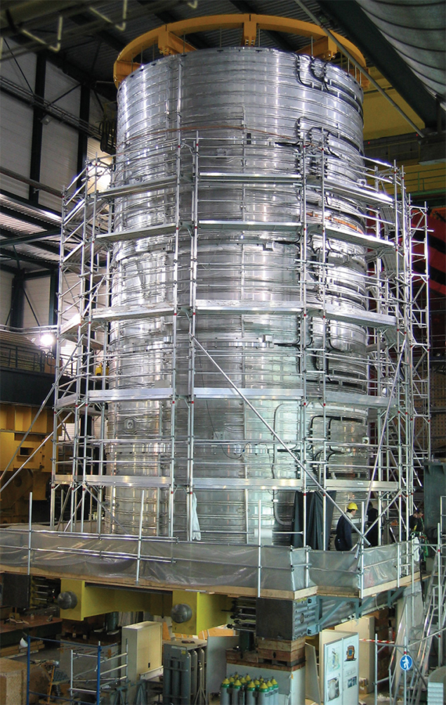
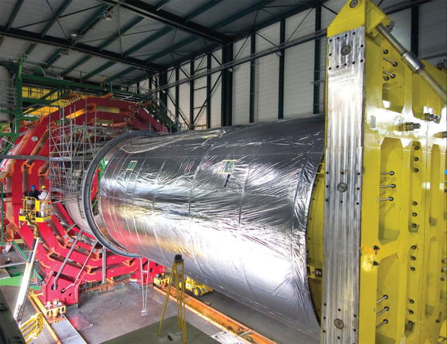
From the start, the idea was to assemble and test the CMS magnet – and the whole detector structure – on the surface prior to lowering it 90 m below ground to its final position. The solenoid consists of five modules that make up a single cylinder (figure 1), while the yoke comprises 11 large pieces that form a barrel with two endcaps. There are six endcap disks and five barrel wheels, and their weight varies from 400 t for the lightest to 1920 t for the central wheel, which includes the coil and its cryostat.
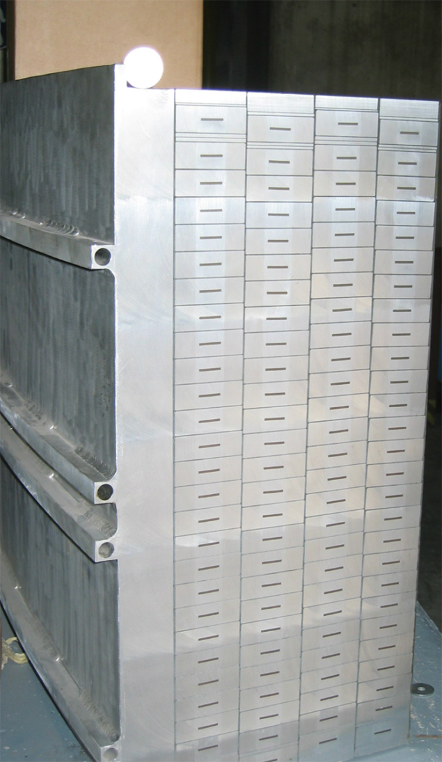
The CMS solenoid has several innovative features compared with previous magnets used in particle-physics experiments. These are necessary to cope with the high ampere turns needed to generate the 4 T field – 46.5 MA around a 6 m diameter. The most distinctive feature is the four-layer coil winding, reinforced to withstand the huge forces at play. The niobium titanium conductor is in the form of Rutherford cable co-extruded with pure aluminium and mechanically reinforced with aluminium alloy (figure 2). The layers of this self-supporting conductor bear 70% of the magnetic stress of 130 MPa while the cylindrical support structure, or mandrel, takes the remaining 30%.
Constructing the coil has been a tour de force in international collaboration involving suppliers in several countries. The basic element, the superconducting wire, originated with Luvata in Finland, and passed to Switzerland, where Brugg Kabelwerk made the Rutherford cable, and Nexans co-extruded it with pure aluminium. The cable then went to Techmeta in France for electron-beam welding onto two sections of high-strength aluminium alloy to allow the conductor to support the high magnetic stress. Finally ASG Superconductors in Italy wound the coils for the five sections of the solenoid, which travelled individually by sea, river and land to Point 5 for assembly into a single coil. The division into sections, and the chosen outer diameter of 7.2 m, ensured that transport could be by road without widening or rebuilding.
By August 2005 the solenoid was ready to be inserted into the cryostat that keeps it at its operating temperature of 4.5 K (figure 3). Cooling requires a helium refrigeration plant with a capacity of 800 W at 4.5 K and 4500 W in the range 60–80 K. The cryoplant was first commissioned with a temporary heat load to simulate the coil and its cryostat, and then early in 2006 the real coil was ready for cool-down. In an exceptionally smooth operation the temperature of the 220 t cold mass was lowered to 4.5 K over 28 days.
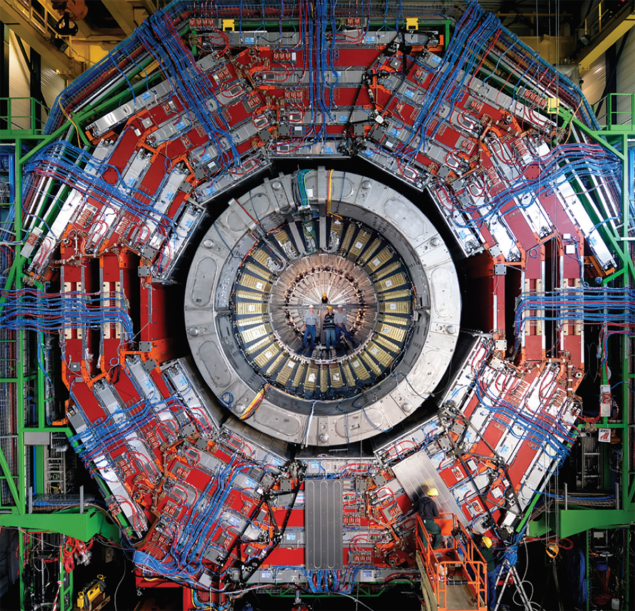
The next stage was to close the magnet yoke in preparation for the MTCC. The massive elements of the yoke move on heavy-duty air pads with grease pads for the final 100 mm of approach. Once an element touches the appropriate stop it is pre-stressed with 80 t to the adjacent element to ensure a good contact before switching on the magnet. To assure good alignment, a precise reference network of some 70 points was set up in the assembly hall, with the result that all elements could be aligned to within 1 mm of the ideal coil axis. The first closure of the whole yoke took some 30 days, and was completed on 24 July (CERN Courier September 2006 cover and p7). The MTCC could now begin.
Testing the magnet took place in two phases, with the initial tests in August 2006 and further tests and field mapping in October. The cosmic challenge, to test detectors and data-acquisition systems with cosmic rays, took place simultaneously. Each step in current ended with a fast discharge into external dump-resistor banks. Depending on the current level at the time of the fast discharge, it could take up to three days to re-cool the coil.
A key feature with any superconducting magnet system is to protect against high thermal gradients occurring in the coil if the system switches suddenly from being superconducting to normally (resistively) conducting with a sudden loss of magnetic field and release of stored energy – a quench. The aim is to dissipate the energy into as large a part of the cold mass as possible. For this reason the CMS solenoid is coupled inductively to its external mandrel, so that in the case of a quench eddy currents in the mandrel heat up the whole coil, dissipating the energy throughout the whole cold mass.
The tests showed that when the magnet discharges the dump resistance warms up by as much as 240°. At the same time the internal electrical resistance of the coil increases, up to as much as 0.1 Ω after a fast discharge at 19 kA.
The tests also showed that after a fast discharge at 19 kA the average temperature of the whole cold mass rises to 70 K, with a maximum temperature difference of 32.3° measured between the warmest part, on the inside of the central section of the coil, and the coldest part, on the outside of the mandrel. It then takes about two hours for the temperature to equalize across the whole coil. About half of the total energy (1250 MJ) dissipates as heat in the external dump resistor, which takes less than two hours to return to its normal temperature.
Monitoring the magnet’s mechanical parameters was also an important feature of the tests, to check for example the coil shrinkage and the stresses on the coil-supporting tie rods during cool-down. The measured values proved to be in excellent agreement with calculations. Powering the cold mass step-by-step allowed also for measurements of any misalignment of the coil. This showed that the axial displacement of the coil’s geometric centre is less than 0.4 mm, indicating a magnetic misalignment of less than 2 mm in the positive z direction.
A major goal of Phase II of the MTCC was to map and reconstruct the central field volume with 5 × 10⁻⁴ precision. The measurements took place in three zones, with flux-loop measurements in the steel yoke, check-point measurements near the yoke elements, and a detailed scan of the entire central volume of the detector – essentially the whole space inside the hadron calorimeter.
Measuring the average magnetic flux density in key regions of the yoke by an integration technique involved 22 flux loops of 405 turns installed around selected plates. The flux loops enclosed areas of 0.3–1.58 m2 on the barrel wheels and 0.48– 1.1 m2 on the endcap disks. The flux loops measure the variations of the magnetic flux induced in the steel when the field in the solenoid is changed during the fast (190 s time constant) discharge. A system of 76 3D B-sensors developed at NIKHEF measured the field on the steel–air interface of the disks and wheels to adjust the 3D magnetic model and reconstruct the field inside the iron yoke elements, which are part of the muon absorbers.
A special R&D programme with sample disks made of the CMS yoke steel from different melts investigated if the measurements of the average magnetic flux density in the yoke plates could be done with accuracy of a few per cent using flux loops. These studies showed that the contribution of eddy currents to the voltages induced in the test flux loop is negligible.
The precise measurement of the magnetic field in the tracking volume inside the CMS coil used a field-mapper designed and produced at Fermilab. This incorporated 10 more 3D B-sensors, developed at NIKHEF and calibrated at CERN to 5 × 10⁻⁴ precision for a nominal field of 4 T. To map a cylindrical volume inside the coil, this instrument moved along the rails installed inside the hadronic barrel calorimeter, stopping in 5 cm steps at points where the sensor arms could be rotated through 360°, and at predefined angles with azimuth steps of 7.5°. Figure 4 shows the final position of the mapper before closure of the positive endcap. It mapped a cylindrical volume 1.724 m in radius and 7 m long.
The CMS magnet has six NMR probes near the inner wall of the superconducting coil cryostat to monitor the magnetic field. These were also used in the field-mapping to measure the field on the coil axis and on the cylindrical surface of the measured volume.
The actual field-mapping in October involved a series of measurements at 0 T, 2 T, 3 T, 3.8 T (twice to study systematics), 3.5 T and 4 T. The flux-loop measurements were made during fast-discharges of the coil at various current values. While the detailed analysis of the data is still ongoing, preliminary studies are very encouraging. The field distribution behaves very much as the simulation predicted – though more detailed simulation of the extra iron in the feet of CMS is necessary to account for it fully.
The azimuthal component of the field is nominally zero, but as the plot shows it takes on small values with a sinusoidal dependence on the rotation angle. This is now fully understood as coming from small tilts of the plane in which the mapper moves with respect to the nominal z axis of the magnetic field; this couples the magnetic field components and also gives rise to the small variations seen in the radial component. In addition, the team now understands some even smaller variations in the sinusoidal behaviour of the azimuthal field as a function of the z step following a careful survey of the tilts induced on the mapper arms as it traversed the length of the coil on its (almost) straight rails.
The electrical tests of the solenoid have demonstrated its excellent performance, as well as the functioning of its ancillary systems, and its readiness for smooth operation. The detailed mapping was equally successful and final analysis is now underway to ensure that the best possible parameterization of the field for analysis of real data in autumn 2007. As soon as the tests were over, the huge sections of yoke were pulled apart again, and the descent to the cavern could at last begin.
Many institutes participating in CMS took part in the design, construction and procurement of the magnet, as members of the CMS Coil Collaboration, including CEA Saclay, ETH Zurich, Fermilab, INFN Genoa, ITEP Moscow, the University of Wisconsin and CERN.


