Behind the scenes at the LHC: A look at some of the main aspects of the LHC’s operation and improving performance.
The total electromagnetic energy stored in the LHC superconducting magnets is about 10,000 MJ, which is more than an order of magnitude greater than in the nominal stored beams. Any uncontrolled release of this energy presents a danger to the machine. One way in which this can occur is through a magnet quench, so the LHC employs a sophisticated system to detect quenches and protect against their harmful effects.
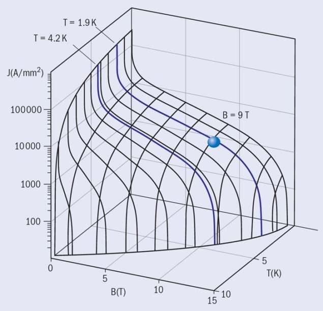
The magnets of the LHC are superconducting if the temperature, the applied magnetic induction and the current density are below a critical set of interdependent values – the critical surface (figure 1). A quench occurs if the limits of the critical surface are exceeded locally and the affected section of magnet coil changes from a superconducting to a normal conducting state. The resulting drastic increase in electrical resistivity causes Joule heating, further increasing the temperature and spreading the normal conducting zone through the magnet.
An uncontrolled quench poses a number of threats to a superconducting magnet and its surroundings. High temperatures can destroy the insulation material or even result in a meltdown of superconducting cable: the energy stored in one dipole magnet can melt up to 14 kg of cable. The excessive voltages can cause electric discharges that could further destroy the magnet. In addition, high Lorentz forces and temperature gradients can cause large variations in stress and irreversible degradation of the superconducting material, resulting in a permanent reduction of its current-carrying capability.
The LHC main superconducting dipole magnets achieve magnetic fields of more than 8 T. There are 1232 main bending dipole magnets, each 15 m long, that produce the required curvature for proton beams with energies up to 7 TeV. Both the main dipole and the quadrupole magnets in each of the eight sectors of the LHC are powered in series. Each main dipole circuit includes 154 magnets, while the quadrupole circuits consist of 47 or 51 magnets, depending on the sector. All superconducting components, including bus- bars and current leads as well as the magnet coils, are vulnerable to quenching under adverse conditions.
The LHC employs sophisticated magnet protection, the so-called quench-protection system (QPS), both to safeguard the magnetic circuits and to maximize beam availability. The effectiveness of the magnet-protection system is dependent on the timely detection of a quench, followed by a beam dump and rapid disconnection of the power converter and current extraction from the affected magnetic circuit. The current decay rate is determined by the inductance, L, and resistance, R, of the resulting isolated circuit, with a discharge time constant of τ = L/R. For the purposes of magnet protection, reducing the current discharge time can be viewed as equivalent to the extraction and dissipation of stored magnetic energy. This is achieved by increasing the resistance of both the magnet and its associated circuit.
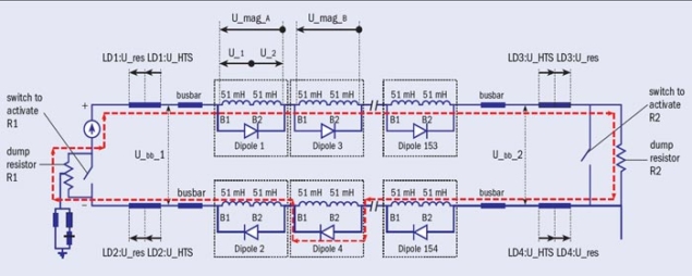
Additional resistance in the magnet is created by using quench heaters to heat up large fractions of the coil and spread the quench over the entire magnet. This dissipates the stored magnetic energy over a larger volume and results in lower hot-spot temperatures. The resistance in the circuit is increased by switching-in a dump resistor, which extracts energy from the circuit (figure 2). As soon as one magnet quenches, the dump resistor is used to extract the current from the chain. The size of the resistor is chosen such that the current does not decrease so quickly as to induce large eddy-current losses, which would cause further magnets in the chain to quench.
Detection and mitigation
A quench in the LHC is detected by monitoring the resistive voltage across the magnet, which rises as the quench appears and propagates. However, the total measured voltage also includes the inductive-voltage component, which is driven by the magnet current ramping up or down. Reliably extracting the resistive-voltage signal from the total voltage-measurement is done using detection systems with inductive-voltage compensation. In the case of fast-ramping corrector magnets with large inductive voltages, it is more difficult to detect a resistive voltage because of the low signal-to-noise ratio; higher threshold voltages have to be used and a quench is therefore detected later. Following the detection and validation of a quench, the beam is aborted and the power converter is switched off. The time between the start of a quench and quench validation (i.e. activating the beam and powering interlocks) must be independent of the selected method of protection.
Creating a parallel path to the magnet via a diode allows the circuit current to by-pass the quenching magnet (figure 2). As soon as the increasing voltage over the quenched coil reaches the threshold voltage of the diode, the current starts to transfer into the diode. The magnet is by-passed by its diode and discharges independently. The diode must withstand the radiation environment, carry the current of the magnet chain for a sufficient time and provide sufficiently high turn-on voltage, to hold during the ramp up of the current. The LHC’s main magnets use cold diodes, which are mounted within the cryostat. These have a significantly larger threshold voltage than diodes that operate at room temperature – but the threshold can be reached sooner if quench heaters are fired.
The sequence of events following quench detection and validation can be summarized as follows:
• 1. The beam is dumped and the power converter turned off.
• 2. The quench-heaters are triggered and the dump-resistor is switched-in.
• 3. The current transfers into the dump resistor and starts to decrease.
• 4. Once the quench heaters take effect, the voltage over the quenched magnet rises and switches on the cold diode.
• 5. The magnet starts now to be by-passed in the chain and discharges over the internal resistance.
• 6. The cold diode heats up and the forward voltage decreases.
• 7. The current decrease induces eddy-current losses in the magnet windings yielding enhanced quench propagation. • 8. The current of the quenched magnet transfers fully into the cold diode.
• 9. The magnet chain is completely switched off a few hundred seconds after the quench detection.
QPS in practice
The QPS must perform with high reliability and high LHC beam availability. Satisfying these contradictory requirements requires careful design to optimize the sensitivity of the system. While failure to detect and control a quench can clearly have a significant impact on the integrity of the accelerator, QPS settings that are too tight may increase the number of false triggers significantly. As well as causing additional downtime of the machine, false triggers – which can result from electromagnetic perturbations, such as network glitches and thunderstorms – can contribute to the deterioration of the magnets and quench heaters by subjecting them to unnecessary spurious quenches and fast de-excitation.
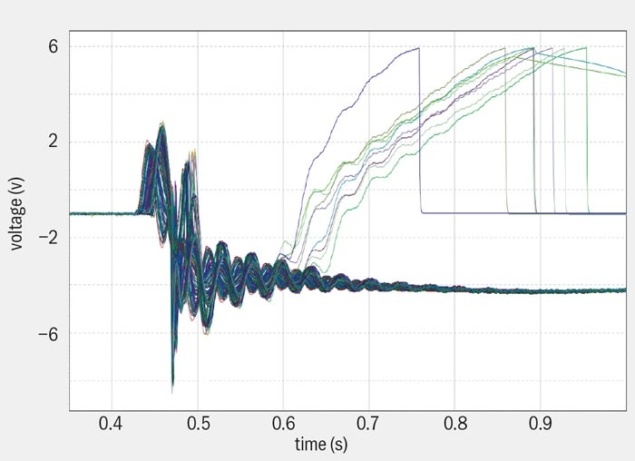
One of the important challenges for the QPS is coping with the conditions experienced during a fast power abort (FPA) following quench validation. Switching off the power converter and activating the energy extraction to the dump resistors causes electromagnetic transients and high voltages. The sensitivity of the QPS to spurious triggers from electromagnetic transients caused a number of multiple-magnet quench events in 2010 (figure 3). Following simulation studies of transient behaviour, a series of modifications were implemented to reduce the transient signals from a FPA. A delay was introduced between switching off the power converter and switching-in the dump resistors, with “snubber” capacitors installed in parallel to the switches to reduce electrical arcing and related transient voltage waves in the circuit (these are not shown in figure 2). These improvements resulted in a radically reduced number of spurious quenches in 2011 – only one such quench was recorded, in a single magnet, and this was probably due to an energetic neutron, a so-called “single-event upset” (SEU). The reduction in falsely triggered quenches between 2010 and 2011 was the most significant improvement in the QPS performance and impacted directly on the decision to increase the beam energy to 4 TeV in 2012.
To date, there have been no beam-induced quenches with circulating beams above injection current
To date, there have been no beam-induced quenches with circulating beams above injection current. This operational experience shows that the beam-loss monitor thresholds are low enough to cause a beam dump before beam losses cause a quench. However, the QPS had to act on several occasions in the event of real quenches in the bus-bars and current leads, demonstrating real protection in operation. The robustness of the system was evident on 18 August 2011 when the LHC experienced a total loss of power at a critical moment for the magnet circuits. At the time, the machine was ramping up and close to maximum magnet current with high beam intensity: no magnet tripped and no quenches occurred.
A persistent issue for the vast and complex electronics systems used in the QPS is exposure to radiation. In 2012 some of the radiation-to-electronics problems were partly mitigated by the development of electronics more tolerant to radiation. The number of trips per inverse femtobarn owing to SEUs was reduced by about 60% from 2011 to 2012 thanks to additional shielding and firmware upgrades. The downtime from trips is also being addressed by automating the power cycling to reset electronics after a SEU. While most of the radiation-induced faults are transparent to LHC operation, the number of beam dumps caused by false triggers remains an issue. Future LHC operation will require improvements in radiation-tolerant electronics, coupled with a programme of replacement where necessary.
Future operation
During the LHC run in 2010 and 2011 with a beam energy of 3.5 TeV, the normal operational parameters of the dipole magnets were well below the critical surface required for superconductivity. The main dipoles operated at about 6 kA and 4.2 T, while the critical current at this field is about 35 kA, resulting in a safe temperature margin of 4.9 K. However, this value will become 1.4 K for future LHC operation at 7 TeV per beam. The QPS must therefore be prepared for operation with tighter margins. Moreover, at higher beam energy quench events will be considerably larger, involving up to 10 times more magnetic energy. This will result in longer recuperation times for the cryogenic system. There is also a higher likelihood of beam-induced quench events and quenches induced by conditions such as faster ramp rates and FPAs.
The successful implementation of magnet protection depends on a high-performance control and data acquisition system, automated software analysis tools and highly trained personnel for technical interventions. These have all contributed to the very good performance during 2010–2013. The operational experience gained during this first long run will allow the QPS to meet the challenges of the next run.


