A look at the devious nature of the fault that brought the LHC to a standstill.
The LHC is probably the largest and most complex scientific instrument ever built. It relies on superconductivity, which plays a fundamental role because it allows magnetic fields in excess of 8 T to be reached. Combined with the radius of curvature of 2.804 km in the dipole (bending) magnets, this field enables proton beams to reach energies of 7 TeV, almost an order of magnitude higher than in previous accelerators. In total there are 1734 large, twin-aperture superconducting magnets, which include the backbone of 1232 main dipoles, each 15 m long. There are also 7724 smaller superconducting corrector magnets. To reach the design performance nearly all of the magnets are cooled with superfluid helium to 1.9 K. The total stored magnetic energy will be about 9000 MJ when running with the dipoles at 8.3 T and a beam energy of 7 TeV.
After 25 years from conception via R&D and construction to commissioning, the LHC started up in spectacular fashion on 10 September 2008. The success of this first commissioning with beam demonstrated the excellent field quality and geometry of the magnets, their precise alignment and good stability, the accuracy of the power supply and the successful operation of the highly complex 1.9 K cryogenic system. Only nine days later, however, in the course of hardware commissioning, a severe incident occurred in sector 3-4 during a ramp of the main dipole current to 9.3 kA (corresponding to a magnetic field of about 6.5 T). It was the final ramp before definitive commissioning of all eight sectors of the machine for operation at 8.6 kA and, hence, an energy of 5 TeV. Many magnets quenched and eventually helium was released into the tunnel and general power was lost in the sector. The incident led to a delay of more than a year before the physics programme began successfully in November 2009.
Collateral damage
The first inspection of the LHC tunnel after the incident revealed considerable damage along a zone about 750 m long. There was deformation of connections, electrical faults, perforation of the helium vessel, local destruction of the beam tube with heavy pollution by debris including fragments of multilayer insulation, breakage or damage of cold support posts, breaches in the interconnection bellows, damage to the warm jacks that support the magnets and cracks in the tunnel floor. The pollution of the beam tubes from tiny confetti-like fragments of insulation extended much further, spanning the sector’s full 3 km-long arc. A task force led by Philippe Lebrun was immediately set up to analyse the incident and propose remedies. Within a month, CERN published the first interim report, followed by a more detailed second report in December 2008. The final report was published at the end of March 2009 (Bajko et al. 2009).
It soon became clear that the root of the incident lay with a single fault in an electrical connection between two adjacent magnets, which had led to extensive collateral damage. A defective joint had created a small resistive zone in a superconducting busbar designed to carry a maximum current of 13 kA. It was a small fault in a relatively low-tech system, but it had dramatic consequences, thanks to the subtleties of superconductivity.
Before discussing this in more detail, it is worth describing the magnet powering and the scheme designed to protect the magnets when a quench occurs. In a quench, a conductor rapidly changes from being superconducting (with no resistance) to being normally conducting (resistive). This transition creates a sudden heating effect in the resistive region. This needs to be controlled swiftly to avoid permanent damage to a magnet because the conductor can no longer sustain the high current, and the magnetic energy – about 7 MJ per dipole magnet – is converted into heat.
Busbars and splices
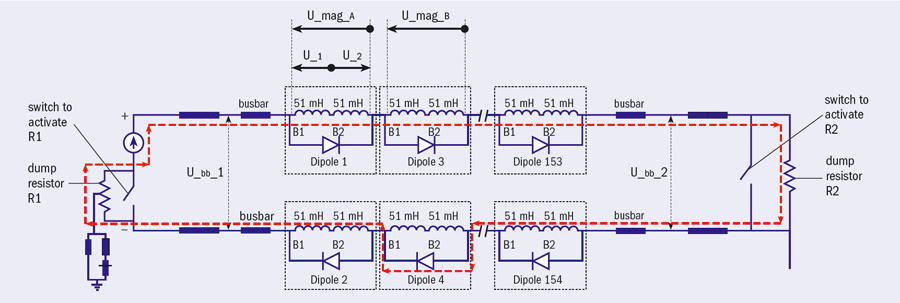
The main magnets of the LHC are connected electrically in a series via 13 kA superconducting busbars in eight main circuits, one per sector. Figure 1 shows a simplified version of the powering and protection scheme for one sector. The 154 dipoles in the sector are powered in series from one 13 kA power convertor – with a dump resistance connected in parallel. The quench-detection system (QDS) monitors for resistive transitions in a magnet by comparing the voltages across the two apertures. When the onset of a quench is detected the system switches in the dump resistor. The inductance, L, of the whole circuit and its resistance, R (determined by the current and maximum voltage), give a 1/e discharge time, L/R, of 104 s, which is far too long for the magnet to survive. Each magnet therefore has a cold bypass-diode and heaters on the coils. As soon as a resistive transition is detected the heaters are fired so as to quench the coils in less than 50 ms. The subsequent sudden rise in voltage turns on the diodes so that they conduct and the current in the quenched coils decays to almost zero in less than 1 s. Meanwhile, all of the unquenched magnets in the sector and the busbars that bypass the quenched coils continue to carry the full current.
The busbars, in which the diodes are inserted, not only bypass any quenched magnet(s) electrically but also serve as a connection between adjacent magnets. So during a magnet quench the busbars carry the overall circuit current, decaying with a time constant of 104 s at the interconnections as well as in the quenched magnet(s). These busbars consist of a superconducting cable that is thermally and electrically coupled to a copper stabilizer along its whole length. The copper cross-section of the stabilizer is designed to be sufficient to carry the current safely, with no damage to the busbar, for the 104-second long discharge even if its superconducting cable is driven into the normal state.
In the case of the incident on 19 September 2008, analysis revealed that a sudden increase of the voltage occurred in the main dipole circuit in sector 3-4, such that the power supply could not deliver the required current. This initiated a fast de-ramp of the magnets, discharging their energy in the dumping system. The discharge was faster than the nominal time constant of 104 s and the circuit quickly became divided into two branches, indicating the presence of a short-circuit. Several magnets quenched.
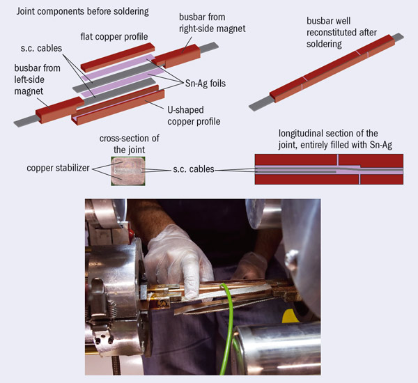
The basic fault appears to have been a defective joint in the 13 kA connection between superconducting cables in two adjacent magnets
The basic fault appears to have been a defective joint in the 13 kA connection between superconducting cables in two adjacent magnets. As figure 2 shows, soft soldering based on tin-silver alloy is used not only to splice the superconducting cable but also to connect the copper stabilizer of the interconnection to both the cable joint and the stabilizing copper of the busbar. When finished, the connection looks like a continuation of the busbars that run along the whole length of the magnet system. The splice between superconducting cables is specified to have a resistance below 0.6 nΩ at 1.9 K. The actual results on samples during production showed an average of 0.2 nΩ with a variance of less than 0.1 nΩ. The resistance of the splice that failed was later evaluated to have been around 220 nΩ.
As they are superconducting, the busbars also have a QDS. This did not intercept the fault, however, because it was not sensitive enough to detect the approximately 2 mV voltage of the resistive zone; the sensitivity was, in fact, 300 mV with an intervention threshold of 1 V. It was subsequently found that, during a current plateau at 7 kA the previous day, sensors on the magnet had indicated a small but distinct increase in temperature of 40 mK above 1.9 K. This was a clear sign of the existence of an abnormal heat dissipation of 10.7 ± 2.1 W, corresponding to a resistance of 180–260 nΩ. (We now know, a posteriori, that we can use this “calorimetric” technique to detect these types of faults.) Had the resistance remained as small as this there would have been no major problem. However, because the current was ramped up to 8.7 kA on 19 September, localized heating increased the resistance, leading to thermal runaway. The heat dissipation was nearly 9 kW by the time the quench-detection threshold of 1 V was reached. Within a second, an electrical arc developed, puncturing the helium enclosure. This led to a release of helium into the insulation vacuum of the cryostat and the subsequent collateral damage described above.
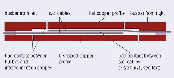
So what had happened? A thermoelectrical model was able to simulate the thermal runaway of the resistive zone in the splice at 8.7 kA, based on the hypothesis of a resistance of 220 nΩ together with a lack of contact between the superconducting cable and copper stabilizer at the joint, as well as the existence of a longitudinal gap in the stabilizer as in figure 3 (Verweij 2009). This discontinuity in the stabilizing copper is important because it impedes the sharing of current between cable and stabilizer. The time constant of the current decay in the busbar is 104 s and the copper there is designed to cope with the heat generated as the current decays in the whole circuit. By contrast, the copper matrix of the superconducting cable is of a size that is sufficient to withstand a discharge time in a resistive state of less than 1 s – the decay time for a single magnet. If there is a discontinuity in the copper stabilizer as well as no contact between the cable and stabilizer, the joint in the superconducting cable cannot sustain the 104 s-long discharge and it melts away.
A subtle enemy
Thus, while the incident was triggered by a bad splice – that is a bad superconductor-to-superconductor joint – the analysis revealed a more subtle possibility. Although the splice between superconducting cables may be good, the surrounding copper stabilizer may not be in contact with the cable, as shown in figure 4. In fact, if the stabilizer is in good contact with the superconducting cable and just has a short longitudinal gap – a few millimetres, say – there is no danger: in a quench of the joint the current can pass through the copper matrix of the superconducting cable and the small amount of heat generated can escape easily via conduction in helium or the busbar.
However, if this gap is coupled with a lack of tin-silver soldering, i.e. the cable at the splice-to-busbar transition is not in good contact with the stabilizing copper for a certain length, then the situation can diverge. The current has to flow through the cable for the whole distance that the cable is isolated and the heat may become too large to escape before a large rise in temperature occurs, initiating thermal runaway and rapidly reaching the melting point in a few seconds. An interconnection joint can be quenched by external heating, for example by warm helium coming from a nearby quenching magnet. The lack of stabilizer continuity could thus cause thermal runaway in the busbar and it turns out to be a more subtle enemy than a bad splice, because it is more difficult to detect.

The task force that investigated the incident proposed a number of remedies, mitigation measures and points to study to improve safety and reliability of the LHC. These included the implementation of a new QDS on the busbars and interconnection line, with a sensitivity threshold of 0.3 mV during a ramp. In a steady state the new QDS can detect a bad splice with a resistance above 1 nΩ. Indeed, the worst interconnection splices have turned out to be about 3 nΩ, far below the runaway threshold, which is estimated to lie well above 50 nΩ.
Moreover, while hunting for bad interconnection splices in October 2008, we realized that the “old” QDS can be used in a measuring mode (rather than the usual active mode) to detect bad splices inside magnets that are in a superconducting state (i.e. at 1.9 K). Although not precise, these (and calorimetric) measurements quickly revealed three magnets (two in the LHC and one in reserve) with defective internal splices of 100, 50 and 25 nΩ. The two installed magnets were replaced, an action that meant that four sectors in total had to be warmed up during the shutdown in 2008–2009. More precise, dedicated tests that were made during the last months with the QDS system in measuring mode found no further bad internal splices, although the system did find 12 dipoles with an internal resistance well above the specification but below 25 nΩ. Internal splices are much less dangerous than interconnection splices because they are covered by the QDS of the magnets, where the current is cut off in less than 1 s. Moreover, all internal splices had been checked during cold-acceptance tests of the magnets at 8.6–9.0 T
The danger of the lack of stabilizer continuity in the busbar required a separate diagnostic method. By measuring a busbar in its resistive state (i.e. warm) over a minimum length (two or three magnets, i.e. 30 or 45 m) one can infer if there is a zone or zones where the cable is not in contact with the stabilizer in conjunction with a gap in the stabilizer. So far this has been done for the four sectors that were warmed up during the long shutdown. In these, all of the bad joints where the defect was longer than 20–25 mm were fixed by resoldering. The other four sectors were measured at 80 K with much less accuracy. As a result one of these sectors was warmed up and three bad joints were repaired, although some defects of almost 40 mm remain, and will be fixed in future.
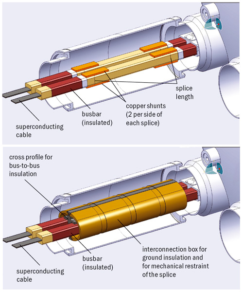
Image credit: P Fessia and H Prin.
In the three sectors that were not warmed up, the inherent uncertainty in the cold measurements, means that defects up to 70 mm long have not been excluded. This limits the maximum safe current for powering the magnets with no risk of thermal runaway in the joints. Different studies based on different models have been made to evaluate the critical defect length, based on input from an experiment performed with a cable insulated from the busbar stabilizing copper for 50 mm. The results of these studies led to the decision to limit the field of the magnets to 4.5 T to begin with, and so allow commissioning with collisions at 3.5 TeV per beam, half of the maximum energy (Myers 2010). The LHC has been operating successfully in this manner since the end of March and will continue to do so throughout 2010 and 2011, allowing the experiments to gather significant amounts of data.
To exploit the full potential of the accelerator by pushing the magnets to 8.3 T, all bad interconnections with the cable detached from the stabilizer copper will have to be fixed. Experience with the sectors that were raised to room temperature during the shutdown suggests that around 10–15% of the joints will need to be resoldered. In addition, we have devised a system that will stabilize all of the interconnections. This involves a relatively simple copper shunt that will be soldered across all of the 10,000 or so interconnections (figure 5). This shunt will definitely cure the issue of the possible lack of continuity of the stabilizer. The aim is to ensure the complete electrical stability of the superconducting magnet system for the LHC’s foreseen lifetime of 25 years (Bertinelli et al. 2010). This will in turn allow the fullest possible returns in terms of new physics in a previously unexplored energy region.
• This article is based on the longer report, Superconductivity: its role, its success and its setbacks in the Large Hadron Collider of CERN (Rossi 2010).