How to build a muon spectrometer to study hot quark matter.
When the LHC begins to open up a new high-energy frontier, it will achieve the highest concentration of energy in operations with lead ions. The collisions, each involving around 400 nucleons with a total energy of more than 1000 TeV, will create strongly interacting, hot, dense matter – a melting pot of quarks and gluons called quark–gluon plasma. This matter will exist for only an instant, and the main goal of the ALICE experiment is to search for evidence of its existence among the many thousands of particles emerging from each collision. One important piece of evidence will be the detection of dimuons – pairs of muons of opposite sign. For this reason, the muon spectrometer, which incorporates some of the first detectors installed in the ALICE underground cavern at Point 2 on the LHC ring, has a key role.
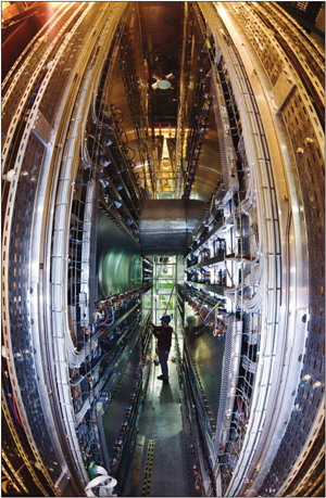
Image credit: A Muller for CERN.
Dimuons are emitted in the decays of vector mesons containing heavy quarks, such as the J/Ψ, the Ψ’, and members of the Υ family. Dimuons will also reveal the decays of light vector mesons (φ, ρ and ω) and of particles with open charm and beauty. The heavy quarkonia states represent one of the most powerful methods to probe the nature of the medium produced in the early stages of the heavy-ion collisions. Indeed, more than 20 years ago, Tetsuo Matsui and Helmut Satz pointed out that J/Ψ production should be suppressed if a quark–gluon plasma is formed in the collision. This provides a strong motivation for experimental studies of J/Ψ and Ψ’ production, undertaken at the energies of the SPS at CERN and RHIC at Brookhaven National Laboratory (BNL). The LHC will be special, however, because two families of resonances (J/Ψ and Υ) rather than one will be experimentally accessible, thanks to the higher beam energy. In addition, the temperature of the quark–gluon “bath” at the LHC is expected to be high enough to “melt” all or most of the Υ states.
Image credit: A Saba for CERN.
As in many experiments, including ATLAS and CMS at the LHC, the role of the muon spectrometer is to detect muons and measure their momenta from the bending of their tracks in a magnetic field. However, there are some very specific aspects of the spectrometer’s design because the ALICE experiment will specialize in studying heavy-ion collisions. In ATLAS and CMS, the muon spectrometer follows the “barrel and endcaps” construction based on a toroidal or solenoidal magnetic field. ALICE also has a central “barrel” of detectors inside the large-aperture solenoid magnet from the L3 experiment at LEP, but the muon spectrometer – with its own large dipole magnet – is located at one side of the barrel, where it will detect muons emitted at small angles with respect to the beam. Isolating muons in heavy-ion collisions requires a large amount of material (absorber) to reduce the huge numbers of hadrons, but the absorbers also stop low-energy muons. So, the measurement of vector mesons (in particular the J/Ψ and Ψ’) of low transverse momentum (pt) is feasible only at small angles, where the muons emitted in their decay have rather high energies owing to the Lorentz boost.
Both the special environment of the heavy-ion collisions and the physics involved have led to other important criteria for the design of the spectrometer. For example, the tracking detectors must be able to handle the high multiplicity of charged particles that are produced. Also, the accuracy of the dimuon measurements is limited by statistics (at least for the Υ family), so the geometrical acceptance must be as large as possible.
The main goal will be to resolve the peaks of the Υ, Υ’ and Υ”, which requires resolutions of 100 MeV/c2 for masses around 10 GeV/c2. This in turn determines the bending strength of the spectrometer magnet as well as the spatial resolution of the muon tracking system. It also imposes the need to minimize multiple scattering in the structure and carefully optimize the absorber. Finally, the spectrometer has to be equipped with a dimuon trigger system that matches the maximum trigger rate handled by the ALICE data acquisition.
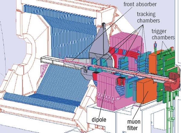
Figure 1 shows the main components of the spectrometer. Closest to the interaction region, there is a front absorber, to remove hadrons and photons emerging from the collision. Five pairs of high-granularity detector planes form the tracking system within the field of the large dipole magnet. Beyond the magnet is a passive muon filter wall, followed by two pairs of trigger chamber planes. In addition, there is an inner beam shield to protect the chambers from particles and secondaries produced at small angles.
The absorbers have a crucial role, so the collaboration has taken great care in their design. The front absorber has to remove hadrons coming from the interaction region without creating further particles and without affecting muons that come from vector meson decays. This absorber is located inside the L3 magnet. It has a composite structure of different materials to limit small-angle scattering and energy lost by the muons and to protect other detectors in ALICE from secondary particles produced in the absorber itself.
Building such a complex item was an impressive international effort. The tungsten came from China, the aluminium from Armenia, the steel from Finland, the graphite from India, the borated polyethylene from Italy, the lead from the UK and the concrete from France. Engineers from Russia and CERN designed the absorber, the Chinese assembled it at CERN and the International Science and Technology Centre in Moscow provided part of the funding.
The spectrometer itself is shielded throughout its length by the beam shield. This is a dense absorber tube made of some 100 tonnes of tungsten, lead and stainless steel, which surrounds the beam pipe. The inner vacuum chamber has an open-angle conical geometry to reduce background particle interactions along the length of the spectrometer.
While the front absorber and the beam shield are sufficient to protect the tracking chambers, the trigger chambers need additional protection. This is provided by an iron wall about 1 m thick – the muon filter – located between the last tracking chamber and the first trigger chamber. Together, the front absorber and the muon filter stop muons with momentum of less than 4 GeV⁄c.
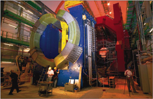
The spectrometer design is constructed around a dipole magnet that is among the largest ever built using resistive coils (figure 2). With a gap between poles of about 3.5 m and a yoke about 9 m high, it weighs 850 tonnes. To provide the required resolution on the dimuon mass, it has a field of 0.7 T, with a field integral between the interaction point and the muon filter of 3 Tm.
There are two main requirements that underpin the design of the tracking system: a spatial resolution better than 100 μm and the capability to operate in the high-multiplicity environment. For central lead–lead collisions, even after the absorbers have done their work, a few hundred particles will nevertheless hit the muon chambers, with a maximum hit density of about 5 × 10⁻² cm–2. Moreover, the system has to cover an area of about 100 m2.
These demands all led to the choice of cathode-pad chambers to detect the muons. There are 10 planes of chambers in all, arranged in pairs to form five stations: two pairs before the dipole magnet; one inside it; and two after. Each chamber has two cathode planes to provide 2D hit information. The read-out pads are highly segmented to keep the occupancy down to around 5%. For example, in the region of the first station close to the beam pipe, where the multiplicity will be highest, the pads are as small as 4.2 × 6.3 mm2. Then, as the hit density decreases with the distance from the beam, larger pads are used at larger radii. This keeps the total number of electronics channels to about 1 million.
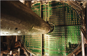
Image credit: Aurélien Muller for CERN.
To minimize the multiple scattering of the muons, the chambers are constructed of composite materials such as carbon fibre. This technology allows for extremely thin and rigid detectors, resulting in the chamber thickness as small as 0.03 radiation lengths. The tracking stations vary in size, ranging from a few square metres for station 1 to more than 30 m2 for station 5. This led to two different basic designs for the chambers. The chambers in the first two stations have a quadrant structure, with the read-out electronics distributed on their surface (figure 3). For the other stations, the chambers have an overlapping slat structure (figure 4) with the electronics implemented on the side of the slats. The maximum size of the slats is 40 × 240 cm2.
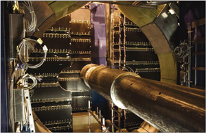
Image credit: Aurélien Muller for CERN.
The front-end electronics for reading out the signals from the tracking chambers is based on custom-designed VLSI chips, developed within the ALICE collaboration. The system uses the MANAS chip, which was derived from the GASSIPLEX chip used for other detectors in ALICE, and the MARC chip. The gain dispersion between the different channels is about 3% – essential for achieving the desired invariant mass resolution. The electronics are completed by the CROCUS system, which was specifically designed and developed to perform the read out of the tracking chambers.
The alignment of the tracking chambers is crucial for achieving the required invariant mass resolution, so there will be a strict procedure to follow when ALICE is running. There will be dedicated runs without magnetic field for aligning the chambers with straight muon tracks. Then, during standard datataking, a dedicated monitoring system will record any displacement with respect to the initial geometry, which can occur for a variety of reasons, including the switching on of the magnet. The geometry-monitoring system consists of 460 optical sensors installed on the tracking chambers. It projects the image of an object onto a CCD sensor and the analysis of the recorded image then provides a measurement of the displacement. The aim is to monitor the position of all of the tracking chambers with a precision better than 40 μm.
Trigger chambers beyond the muon filter form the final important component of the muon system. The role of the trigger detectors is to select dimuons produced (e.g. by J/Ψ or Υ decays) from the background of low-pt muons produced by the decays of pions and kaons. The selection is made on the pt of each individual muon, yielding a dimuon trigger signal when there are at least two tracks above a predefined pt. This pt selection needs a position-sensitive trigger detector with a spatial resolution of better than 1 cm – a requirement that is fulfilled by resistive plate chambers (RPCs). These detectors will be operated in streamer mode during heavy-ion runs.
The trigger system consists of four RPC planes, with a total active area of about 150 m2, arranged in two stations, 1 m apart, behind the muon filter. The RPC electrodes are made of low-resistivity Bakelite (about 3 × 10⁹ Ωcm) so as to achieve the rate capability in the heavy-ion collisions. They are coated with linseed oil to improve the smoothness of the electrode surface. Extensive tests have shown that the RPCs will be able to tolerate several years of data taking in ALICE with heavy-ion beams.
The front-end electronics for the trigger detectors is based on the ADULT integrated circuit, also developed within the ALICE collaboration. Although designed for optimizing the time resolution when the RPCs operate in streamer mode, the circuit also allows the chambers to operate in “avalanche mode” during the long proton–proton runs that will occur at the LHC. The signals from the trigger detectors pass to the trigger electronics, which performs the pt selection on each muon. If the muon trigger is fired, a dedicated electronics card called the DARC allows the transfer of the trigger data to the ALICE data acquisition. Thanks to a short decision time of about 700 ns with these electronics, the dimuon trigger forms part of the level-0 trigger for ALICE. A high-level trigger system – based on the analysis by a PC farm of the final two tracking stations – further refines the selection of good events.
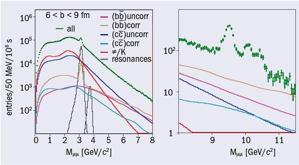
The collaboration has developed a detailed simulation to evaluate the performance of the muon spectrometer for the vector meson and heavy-flavour studies, using as input current knowledge about the different processes that contribute to dimuon production at LHC energies. Figure 5 shows an example of such studies, in this case the invariant mass distributions in the regions of the J/Ψ and Υ mass for lead–lead collisions in ALICE. This demonstrates the spectrometer’s capability to detect these resonances against various sources of background.
For the past few years, components built for the spectrometer have arrived at CERN from many different collaborating institutes and suppliers. The two coils for the spectrometer dipole magnet arrived at CERN in September 2003 and the complete magnet was installed in its final position underground in summer 2005. A year later, dimuon trigger and tracking chambers were the first detectors to be installed in ALICE’s underground cavern in July 2006. Since then installation and commissioning have maintained a good pace, and the dimuon spectrometer should be ready for the first global tests of ALICE at the end of the year.
• The design and construction of the ALICE muon spectrometer have been made possible through the joint efforts of many institutions in different countries: CEA/DAPNIA Saclay, IPN Lyon, IPN Orsay, LPC Clermont-Ferrand, LSPC Grenoble and Subatech Nantes (France); CERN Geneva (Switzerland); INFN/University of Cagliari, INFN/University of Torino, University of Piemonte Orientale and INFN Alessandria (Italy); JINR Dubna, PNPI Gatchina and VNIIEF Sarov (Russia); KIP Heidelberg (Germany); Muslim University of Aligarh and SAHA Institute Kolkata (India); University of Cape Town (South Africa); and Yer-Phi Yerevan (Armenia).