The ATLAS collaboration gathers speed in commissioning its subdetectors.
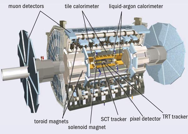
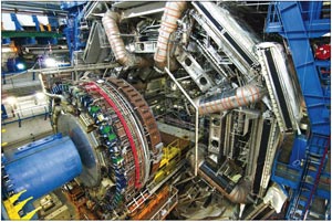
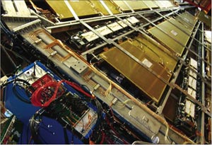
In the time since the vast underground cavern that houses the ATLAS experiment for the LHC was completed in 2003, it has gradually filled with the many different components that make up the largest-volume collider detector ever built (figure 1). Installation is due to be complete in early 2008. Meanwhile, commissioning the various subdetectors underground has been progressing in parallel. June saw the successful completion of the third “milestone week” (M3) in the global commissioning process. For the first time, the tests involved components from the tracking system as well as the calorimetry and muon detection systems, and each detector was operated from within the ATLAS control room.
The milestone weeks are dedicated to operating the experiment as a whole, from subdetector to permanent data storage, with an increasing number of subdetector systems involved at each stage. Even if a particular subdetector is not fully installed, these tests can still incorporate parts that are ready in order to exercise as many steps in the detection and data collection chain as possible. Keeping a sub-system that is still being installed in stable running conditions for many hours over many days is no small challenge. Multiply this by the 12 subdetectors involved, and add the computing, power and cooling infrastructure, detector control systems (DCSs) and safety systems, and it might seem questionable that it can work at all. But work it did during the M3 period, which in fact ran over two weeks from 4 to 18 June.
The first week of M3 was dedicated to the stable running of systems that had been integrated in previous exercises, with the emphasis this time on monitoring and exercising the formal procedures for running shifts when the experiment begins full operation in 2008. The subdetectors involved in this first week were the liquid-argon and tile calorimeters, together with part of the muon spectrometer (barrel and endcap). Each detector was initialized and monitored from a dedicated desk in the ATLAS control room, with the overall running controlled from the run-control desk.
The tile calorimeter, which basically consists of a steel-scintillator sandwich, is designed to measure the energy of hadrons emerging at angles greater than 25° to the beam. For hadron calorimetry between 25° and 5° in the endcaps, liquid argon and copper take over, with a different variation based on a tungsten absorber in the forward direction (less than 5°). Liquid argon also figures in the electromagnetic calorimeter, which is optimized for electrons and photons. However, in this case, lead (rather than copper) is used to initiate particle showers.
For the M3 tests, around 75% of the tile calorimeter and 50% of the liquid argon calorimeter were powered with high voltage and included in the final digital read-out. The tile calorimeter will provide a fast read-out for triggering when finally operational at the LHC, adding together calorimeter cells into trigger towers that point to the interaction point. In the M3 set-up, 500 trigger towers (around 25% of the final number) were used to provide a first-level trigger on cosmic muons, supplying signals to special trigger electronics for commissioning, which in turn delivered a trigger signal to the central trigger processor. This yielded a couple of cosmic events per minute that were read out by the central data acquisition (DAQ). During the run, a dozen or so non-expert “shifters” looked after routine operations, such as data and hardware monitoring, testing procedures as well as the detector systems.
The muon system for ATLAS is based on the huge toroid magnet system, with several different kinds of detector to register and track muons as they pass beyond the layers of calorimetery. Monitored drift tubes (MDTs) provide the precision measurements in the bending region of the magnetic field in both the barrel and the endcap region of the detector. They are complemented by trigger chambers – resistive plate chambers (RPCs) in the barrel and thin gap chambers (TGCs) in the endcap regions – which provide fast signals for the muon trigger and the second co-ordinate for the measurement of the muon momentum.
For the barrel muon detectors, sections of both the MDTs and the RPCs took part in the M3 tests using the final set-up for the high-voltage, low-voltage and gas systems, and all monitored by the central DCS. Some 27,000 drift tubes were read out during the run, which is more than the barrel muon read-out of the LEP experiments (e.g. ALEPH had approximately 25,000 muon channels) but is less than 10% of the final total for ATLAS. Two sectors of RPCs were used to provide a trigger on cosmic muons.
The integration of new components into the global system formed the main goal of week two, which saw the addition of detectors from the inner tracking system and more trigger equipment. The inner detector uses three different systems for tracking particles within the volume of a superconducting solenoid magnet inside the calorimeters. The tracking systems form three layers, the outermost being the transition radiation tracker (TRT) based on “straws” (4 mm diameter drift tubes). Silicon strip detectors in the semiconductor tracker (SCT) are used at radii closer to the beam pipe, while silicon pixel detectors form the innermost layer.
The barrel TRT was successfully installed and tested in October 2006. Since then a number of stand-alone and system tests combined with the SCT have taken place to characterize the detector. For M3, six TRT barrel modules – altogether 20,000 channels or 19% of the TRT barrel – were connected to the back-end read-out electronics and successfully integrated into the central DAQ. Steps were also taken towards the integration of the TRT DCS into the ATLAS DCS, and cosmic-ray data were collected in combination with other detectors by the end of the M3 period (figure 2).
Cooling for the SCT was not available during the M3 run, so this detector could not take part fully. However, its DAQ was nonetheless successfully integrated using some test modules installed adjacent to the SCT read-out driver (ROD) crates. Despite using only a small number of modules, M3 provided a valuable opportunity to exercise the final DAQ infrastructure and the functionality of the trigger timing in preparation for running with the full SCT.
On the second week of the run, the first-level calorimeter trigger (L1Calo) also joined the data collection, taking part for the first time in a milestone run, although not yet providing real triggers. For this initial test, the system consisted of one-eighth of the final set of preprocessor modules and one ROD. The pre-processor modules perform the analogue-to-digital conversion for L1Calo and will also identify the bunch-crossing that the signals have come from when there is beam in the LHC. Running this system was smooth and provided valuable experience of stable running with parts of the final trigger hardware integrated with the other ATLAS subsystems.
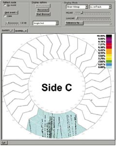
For the muon system, elements of the endcap wheels were brought into the trigger during the second week. The TGCs, which provide the level-1 trigger for the muon-endcaps, had already been integrated into the central trigger and DAQ system, but on 13 June some of them were used for the first time to provide a cosmic-ray trigger to other subdetectors, in particular endcap monitored drift tube chambers. This involved 1 out of the 72 sectors of TCGs, using final chambers, electronics equipment and DCS (figure 3). The alignment of the TGCs was sufficiently well known that triggers from cosmic rays were produced with good efficiency at a rate of 3 Hz.
The region of interest builder (RoIB) was another component of the final trigger hardware that was successfully integrated during M3. Although the first-level trigger decision is based on the multiplicity of objects, and not on their position, the first-level trigger processors do remember where they encountered objects passing their thresholds, and, for events accepted by the first-level trigger, they pass this information on to level 2. The role of the custom-built electronics forming the RoIB is to receive these region of interest fragments from the first-level muon and calorimeter trigger subsystems and the central trigger processor, and then to combine them into a single record that is passed on to the level-2 trigger supervisor. The initial hardware for the high-level trigger (level-2 and Event Filter) was also successfully integrated. This consisted of 20 level-2 nodes running cosmic algorithms (but not rejecting events) and 10 event filter nodes (without algorithm processing), which passed data to one of six subfarm output units (SFOs) in the final system. The SFO was able to write events to disk at a rate of up to 70 MB/s and subsequently transferred these files to CASTOR, the data storage on the CERN site, at a rate of around 35 MB/s.
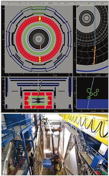
M3 provided the first opportunity for Tier-0 processing to take part in a real data-taking exercise. The existing Tier-0 infrastructure, so far only used in large-scale tests decoupled from the on-line world, was adapted to the needs of M3 and run during almost the whole data-taking period. Its tasks were to pick up the data files written to CASTOR by the DAQ and to run the offline reconstruction. For the first time, the complete offline software chain could reconstruct cosmic-ray events from data in the calorimeters, the inner detector and part of the muon system (figure 4).
The full monitoring chain was also running, taking the different reconstructed objects as input and producing the relevant monitoring histograms for each subdetector in order to check its correct performance. In a subsequent processing step, monitoring histograms produced as outputs of the individual reconstruction jobs were also merged to allow data quality monitoring over longer periods of time.
Progress during M3 – the third “mile” – has demonstrated that almost all of the subsystems of ATLAS can work together in at least a fraction of their final size, and, in the case of the calorimeters, a large fraction. There are still a few more miles to go. The challenge will be to increase the system in size as commissioning continues while keeping the running-efficiency high and the failure-rate low.