The first stage of the refrigeration system for the Large Hadron Collider is now installed and ready for the initial cooling tests in 2005, as Laurent Tavian describes.
When the Large Hadron Collider (LHC) begins operation at CERN it will be one of the coldest places on Earth. To keep the protons on course around the LHC and at the same time attain as high an energy as reasonably possible requires powerful superconducting magnets, which will operate at a temperature of 1.9 K – only 1.9 degrees above the absolute zero of temperature and chillier than outer space. While there may indeed be colder places in other laboratories, none will be on the scale of the LHC. The task of keeping the 27 km long structure at 1.9 K will be performed by helium, which will itself be cooled to its superfluid state in a huge refrigeration system.
The choice of the operating temperature for the LHC has as much to do with the “super” properties of helium as with those of the superconducting niobium-titanium alloy in the magnet coils. At atmospheric pressure helium gas liquefies at around 4.2 K, but when it is cooled further it undergoes a second phase change at about 2.17 K to its superfluid state. Among many remarkable properties, superfluid helium has a very high thermal conductivity, which makes it the coolant of choice for the refrigeration and stabilization of large superconducting systems. Indeed, the LHC cryogenic system will carry kilowatts of refrigeration over more than 3 km with a temperature drop from 1.9 to 1.8 K – less than 0.1 K.
From the cryogenic point of view, the LHC is a large distributed helium system operating at a variety of temperature levels down to 1.8 K. As well as being constructed in the tunnel built originally for the Large Electron Positron collider, LEP, to keep costs down the cooling system has been designed around the four 4.5 K refrigeration plants that were used to cool the superconducting radiofrequency cavities for the second phase of the LEP collider, LEP2. (The tunnel is not the only part of LEP to be “recycled” for the LHC!) The design of these refrigeration plants sets the temperature levels for the whole system at 75, 50, 20 and 4.5 K, in addition to the ultimate temperature level produced by the 1.8 K refrigeration system that provides the superfluid helium to the “cold mass” containing the superconducting coils.
The LHC will consist of eight 3.3 km long sectors, with access shafts to services on the surface only at the ends of each sector. The layout for the refrigeration system is therefore based on five “cryogenic islands” – three of which serve two sectors, while two serve a single sector each. Thus each “island” must distribute and recover coolant over a distance of 3.3 km.
Among the main components for this refrigeration system are eight 4.5 K refrigerators – one for each sector – each with a capacity of 18 kW at 4.5 K. Four of these have been recovered from LEP, and they will be upgraded to operate on the sectors with a slightly lower demand for refrigeration. The four high-load sectors will be cooled by new 4.5 K refrigerators, the last of which passed its acceptance procedures towards the end of 2003.
The refrigeration power needed to cool the 4700 tonnes of material of each sector of the LHC is enormous and can only be produced by using liquid nitrogen. Consequently, each 4.5 K refrigerator is equipped with a 600 kW liquid-nitrogen pre-cooler, which will be used to pre-cool a flow of helium down to 80 K while the corresponding sector is being cooled and later filled with helium – a procedure that will take just under two weeks. Using no liquid nitrogen but only helium in the tunnel considerably reduces the risk of oxygen deficiency in the case of accidental release.
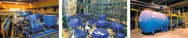
The 4.5 K refrigeration system works by first compressing the gas and then allowing it to expand. While it expands it cools by losing energy through mechanical turbo-expanders that run at up to 120,000 rpm on helium-gas bearings. Only two companies in the world provide turbo-expanders with sufficient cooling power – Air Liquide in France and Linde in Switzerland. Each of the refrigerators consists of a helium compressor station equipped with oil and water removal systems and a vacuum-insulated cold box (60 tonnes) where the process fluid is cooled, purified and liquefied. The compressor station supplies compressed helium gas at 20 bar and room temperature. The cold box houses the heat exchangers and turbo-expanders that provide the cooling capacities necessary at the different temperature levels and liquefy the helium to 4.5 K before it passes to the 1.8 K refrigeration unit. Each refrigerator is equipped with a fully automatic process control system that manages about 1000 inlets and outlets per plant.
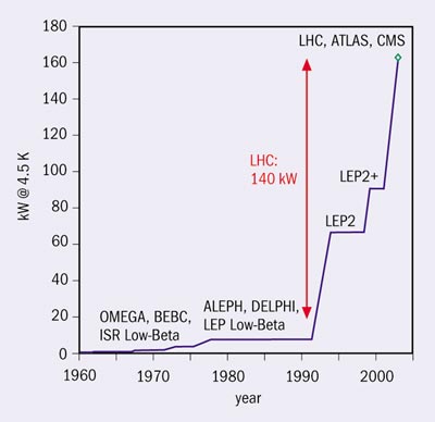
The complete system of eight 4.5 K refrigerators takes the cooling capacity at 4.5 K to 140 kW, that is almost 40,000 litres of liquid helium per hour. This is huge progress since LEP2, to say nothing of the days before LEP when most cryogenic needs were for individual experiments (figure 1). An electrical input power of 32 MW (4 MW per refrigerator) will be needed to produce this capacity at 4.5 K.
The process of bringing together the new 4.5 K refrigerators began in 1998 when contracts were signed with Air Liquide and Linde. The design and industrial engineering phases that followed made it possible for the first deliveries to take place from the middle of 2000, while LEP was still in operation. After a period of intensive tests the first new refrigerator for the LHC, built by Air Liquide, was accepted at Point 1.8 in March 2002. It has since been used to supply the test benches for the superconducting magnets. In December 2002 a second Air Liquide refrigerator was accepted at Point 4, followed by the two refrigerators manufactured by Linde in August and December 2003 at Points 8 and 6.
Of course the story does not end with the installation of the 4.5 K refrigerators. From now on the LHC cryogenic team will focus on upgrading the four LEP refrigerators already in place at Points 2, 4, 6 and 8. Simultaneously, they will finish installing the cryogenic infrastructure and 1.8 K refrigeration units to supplement the 4.5 K system. These installations will gradually be brought into operation to test the other cryogenic assemblies (vertical transfer lines, interconnection boxes, local transfer lines and tunnel distribution lines). This should enable final adjustments to be made and provide the experience necessary to face up to the next challenge, that of cooling the first sector of the machine in 2005.